EP0840039A2 - Segment râcleur d'huile en deux pièces pour moteur à combustion interne. - Google Patents
Segment râcleur d'huile en deux pièces pour moteur à combustion interne. Download PDFInfo
- Publication number
- EP0840039A2 EP0840039A2 EP97118989A EP97118989A EP0840039A2 EP 0840039 A2 EP0840039 A2 EP 0840039A2 EP 97118989 A EP97118989 A EP 97118989A EP 97118989 A EP97118989 A EP 97118989A EP 0840039 A2 EP0840039 A2 EP 0840039A2
- Authority
- EP
- European Patent Office
- Prior art keywords
- side rail
- control ring
- base
- oil control
- supports
- Prior art date
- Legal status (The legal status is an assumption and is not a legal conclusion. Google has not performed a legal analysis and makes no representation as to the accuracy of the status listed.)
- Withdrawn
Links
- 238000002485 combustion reaction Methods 0.000 title claims abstract description 13
- 125000006850 spacer group Chemical group 0.000 claims abstract description 30
- 229910000831 Steel Inorganic materials 0.000 description 1
- 230000007547 defect Effects 0.000 description 1
- 238000004519 manufacturing process Methods 0.000 description 1
- 239000002184 metal Substances 0.000 description 1
- 230000004048 modification Effects 0.000 description 1
- 238000012986 modification Methods 0.000 description 1
- 239000010959 steel Substances 0.000 description 1
Images


Classifications
-
- F—MECHANICAL ENGINEERING; LIGHTING; HEATING; WEAPONS; BLASTING
- F16—ENGINEERING ELEMENTS AND UNITS; GENERAL MEASURES FOR PRODUCING AND MAINTAINING EFFECTIVE FUNCTIONING OF MACHINES OR INSTALLATIONS; THERMAL INSULATION IN GENERAL
- F16J—PISTONS; CYLINDERS; SEALINGS
- F16J9/00—Piston-rings, e.g. non-metallic piston-rings, seats therefor; Ring sealings of similar construction
- F16J9/06—Piston-rings, e.g. non-metallic piston-rings, seats therefor; Ring sealings of similar construction using separate springs or elastic elements expanding the rings; Springs therefor ; Expansion by wedging
- F16J9/064—Rings with a flat annular side rail
- F16J9/066—Spring expander from sheet metal
-
- F—MECHANICAL ENGINEERING; LIGHTING; HEATING; WEAPONS; BLASTING
- F16—ENGINEERING ELEMENTS AND UNITS; GENERAL MEASURES FOR PRODUCING AND MAINTAINING EFFECTIVE FUNCTIONING OF MACHINES OR INSTALLATIONS; THERMAL INSULATION IN GENERAL
- F16J—PISTONS; CYLINDERS; SEALINGS
- F16J9/00—Piston-rings, e.g. non-metallic piston-rings, seats therefor; Ring sealings of similar construction
- F16J9/12—Details
- F16J9/20—Rings with special cross-section; Oil-scraping rings
- F16J9/203—Oil-scraping rings
-
- F—MECHANICAL ENGINEERING; LIGHTING; HEATING; WEAPONS; BLASTING
- F16—ENGINEERING ELEMENTS AND UNITS; GENERAL MEASURES FOR PRODUCING AND MAINTAINING EFFECTIVE FUNCTIONING OF MACHINES OR INSTALLATIONS; THERMAL INSULATION IN GENERAL
- F16J—PISTONS; CYLINDERS; SEALINGS
- F16J9/00—Piston-rings, e.g. non-metallic piston-rings, seats therefor; Ring sealings of similar construction
- F16J9/06—Piston-rings, e.g. non-metallic piston-rings, seats therefor; Ring sealings of similar construction using separate springs or elastic elements expanding the rings; Springs therefor ; Expansion by wedging
- F16J9/064—Rings with a flat annular side rail
Definitions
- the insufficient follow-up property of the side rail allows to produce, between the side rail and the inner wall of the cylinder during operation of the engine, radial clearance or gap which increases amount of oil entering a combustion chamber for increase of oil consumption. Therefore, in some cases, the engine cannot generate full power due to increase of oil amount entering the combustion chamber or may produce trouble in operation.
- a typical oil control ring of three piece type mainly applied to current internal combustion engines comprises a space expander and a pair of side rails positioned on and beneath the space expander.
- prior art oil control rings indicate various defects. Firstly, high rigidity of the spacer expander causes insufficient contact of the side rail with an inner wall of a cylinder along the outer periphery of the side rail due to deformation of the cylinder bore at an elevated temperature. Secondly, the spacer expander does not produce deflection in the sliding direction so that the inner periphery of the side rail is always kept in close contact to an upper surface of the annular groove formed on the cylinder during upward stroke of the piston, and therefore no radial passage can be formed between the side rail and upper surface of the annular groove to drain oil scraped by the side rail. Thirdly, oil control rings cannot be made into thin structure in accordance with requirement of light weight and high speed engines.
- an object of the present invention is to provide an oil control ring of two piece type made in thin structure.
- Another object of the invention is to provide an oil control ring capable of producing a radial passage between a side rail and an upper surface of an annular groove of a piston during the upward stroke to drain oil scraped by the side rail through the radial passage.
- Still further object of the invention is to provide an oil control ring operable with reduced oil consumption.
- the oil control ring is adapted to be attached in an annular groove formed in a piston for internal combustion engine.
- the oil control ring includes a spacer expander and a side rail mounted thereon and urged toward an inner wall of a cylinder by elastic force of the spacer expander.
- the spacer expander comprises a base, a plurality of supports and a plurality of arms.
- the supports and arms are integrally formed with the base to extend from an inner periphery or outer periphery of the base.
- the supports resiliently urges the side rail toward an upper surface of the annular groove of the piston.
- Each of the arms is provided with a lug for resiliently urging the side rail in radial and outward direction.
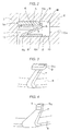
- the spring portion 16 diagonally extends from the outer periphery 8a of the base 8 within the annular groove 10.
- the table portion 17 is substantially in parallel relation to the upper surface 14 of the annular groove 10 to uniformly urge the side rail 5 throughout the whole circumference toward the upper surface 14 of the annular groove 10.
- Each of the arms 7 extends from the inner periphery or outer periphery of the base 8 independently of the supports 6 so that the lug 9 is in contact with the inner periphery 5b of the side rail 5 and produces its elastic force to radially outwardly expand the side rail 5.
- the side rail 5 is positioned on the table portion 17 so that the supports 6 resiliently upwardly urges the side rail 5 toward an upper surface 14 of the annular groove 10 of the piston 2.
- the table portion 17 may also produce resilient force to elastically urge the side rail 5 toward the upper surface 14 of the groove 10 of the piston 2 in addition to the spring portion 16.
- the flat bottom surface of the base 8 stably retains the space expander 4 on the bottom surface 12 of the annular groove 10 of the piston 2, and the flat bottom surface of the base 8 reduces wear of the bottom surface 12 of the groove 10.
- the side rail 5 is resiliently urged toward an inner wall 13 of a cylinder 3 by elastic force of the spacer expander 4.
- An outer periphery 5a of the side rail 5 is protruded outwardly of the spacer expander 4 to contact the inner wall 13. Not shown but, each of the spacer expander 4 and side rail 5 has a closed gap to attach them in the annular groove 10.
- a radial opening 10a is formed to communicate the annular groove 10 of the piston 2 with a crank chamber for return of oil.
- Each of the arms 7 is provided with a lug 9 which has an inclined surface 9a in contact to an inner periphery 15 of the side rail 5 to outwardly resillently urge the side rail 5 toward the inner wail 13 of the cylinder 3.
- the inner periphery of the side rail 5 is radially outwardly and upwardly pushed by the inclined surface 9a which forms an angle ⁇ up to 30 degrees relative to a vertical direction.
- the bottom portion of each lug 9 is positioned approximately at a same level as that of an upper surface of the table portion 17.
- the combined width of the spacer expander 4 and side rail 5 is in a range of 1 millimeter to 4 millimeters.
- the support 6 of the spacer expander 4 may have its sectional area, shape and length to provide appropriate rigidity and deflection of the support 6 so that during the upward stroke of the piston 2 it can be deformed to produce a radial passage between the side rail 5 and upper surface of the annular groove 10 of the piston 2, and therefore oil scraped by the side rail 5 can be drained through the radial passage and the opening 10a.
- the side rail 5 is resiliently outwardly urged by the lugs 9 formed in the arm 7 independently of the supports 6 so that the side rail 5 can be brought into close contact with the inner wall 13 of the cylinder 3 to provide sufficient seal to the inner wall 13, and therefore, the outer periphery 5a of the side rail 5 can follow thermal deformation of the cylinder 3 at an elevated temperature.
- the spring portion 16 of the support 6 is so compressed during the upward stroke of the piston 2 that the outer periphery 17a of the table portion 17 may be lowered below the inner periphery 17b of the table portion 17 to maintain the inner periphery 5b of the side rail 5 above the outer periphery 5a of the side rail 5.
- the side rail 5 is supported on two portions of the outer periphery 17a of the table portion 17 and the lug 9.
- T in Fig. 2 indicates the whole width of the oil control ring 1
- t indicates length from the outer periphery 5a to the outer periphery 17a of the table portion 17
- (t/T) X 100 10 to 60 % .
- the outer periphery 17a of the table portion 17 contacted with the bottom surface of the side rail 5 is preferably positioned 10 to 60 % from the outer periphery 5a of the side rail 5 in view of the total width T of the oil control ring 1.
- Fig. 3 shows a second embodiment of then arm 7 according to the present invention wherein the arm 7 is formed into a thin section of substantially same width, but the lug 9 can be formed with its greater wide than that of the arm 7.
- the arm 7 and lug 9 can be tapered.
- Fig. 5 represents a fourth embodiment of the present invention wherein a same rectangular section area can be given to the arm 7 and lug 9. While Figs.
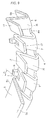
- Fig. 6 indicates that the arms 7 may be extended from the inner periphery 8b of the base 8 in a fifth embodiment of the present invention.
- the supports 6 have their Z-shaped section with the base 8
- the arms 7 have their L-shaped section.
- Fig. 8 shows a sixth embodiment of the invention wherein the spring portions 16 may be extended from the inner periphery 8b of the base 8 in an intersecting condition of the spring portion 16 in a projection view with the arms 7 extended from the outer periphery 8a of the base 8.
- the worked mode of the instant invention can give rise to many advantages.
- Adoption of suitable section area, shape and length of the spring portion 16 and table portion 17 can realize a maximal rigidity and deflection of the support 6 to support the side rail 5.
- selection of the projecting length of the support 6 from the base portion 8 is effective to adjust the deflected amount of the support 6.
- Each support 6 of V-shape provides a given elasticity, rigidity and deflection in the sliding direction.
- the supports 6 of the spacer expander 4 can be resiliently deformed in the vertical direction to form between the side rail 5 and upper surface of the annular groove 10 the radial passage through which oil scraped by the side rail 5 can be drained.
- the flat bottom surface of the base 8 stably retains the space expander 4 on the bottom surface 12 of the annular groove 10 of the piston 2, reducing wear of the bottom surface 12 of the groove 10.
- the side rail 5 is resillently outwardly urged by the lugs 9 formed in the arm 7 independently of the supports 6 so that the side rail 5 can be brought into close contact to the inner wall 13 of the cylinder 3 to provide sufficient seal to the inner wall 13, and it can follow deformation of the cylinder 3 at an elevated temperature.
- the oil control ring 1 can be made into a thin structure of two piece type because the supports 6 and arms 7 are integrally formed with the base 8 above the same side thereof.
Landscapes
- Engineering & Computer Science (AREA)
- General Engineering & Computer Science (AREA)
- Mechanical Engineering (AREA)
- Pistons, Piston Rings, And Cylinders (AREA)
Applications Claiming Priority (2)
| Application Number | Priority Date | Filing Date | Title |
|---|---|---|---|
| JP8290085A JPH10132078A (ja) | 1996-10-31 | 1996-10-31 | 内燃機関用組み合わせオイルコントロールリング |
| JP290085/96 | 1996-10-31 |
Publications (2)
| Publication Number | Publication Date |
|---|---|
| EP0840039A2 true EP0840039A2 (fr) | 1998-05-06 |
| EP0840039A3 EP0840039A3 (fr) | 1999-05-19 |
Family
ID=17751610
Family Applications (1)
| Application Number | Title | Priority Date | Filing Date |
|---|---|---|---|
| EP97118989A Withdrawn EP0840039A3 (fr) | 1996-10-31 | 1997-10-30 | Segment râcleur d'huile en deux pièces pour moteur à combustion interne. |
Country Status (4)
| Country | Link |
|---|---|
| US (1) | US5964467A (fr) |
| EP (1) | EP0840039A3 (fr) |
| JP (1) | JPH10132078A (fr) |
| KR (1) | KR19980033372A (fr) |
Families Citing this family (6)
| Publication number | Priority date | Publication date | Assignee | Title |
|---|---|---|---|---|
| DE10340302A1 (de) * | 2003-09-02 | 2005-04-14 | Mahle Gmbh | Ölabstreifring für Kolben von Verbrennungsmotoren |
| US8740225B2 (en) * | 2009-06-03 | 2014-06-03 | Exponential Technologies, Inc. | Hydrodynamic bore seal |
| BR102012019166B1 (pt) * | 2012-07-31 | 2020-05-19 | Mahle Metal Leve S/A | anel de controle de óleo de três peças para motores de combustão interna. |
| BR112019003747B1 (pt) * | 2017-09-29 | 2022-08-30 | Tpr Co., Ltd | Segmento, anel de óleo de combinação, e método de fabricação para um segmento |
| KR20200108282A (ko) | 2017-12-13 | 2020-09-17 | 엑스퍼넨셜 테크놀로지스 주식회사 | 회전식 유체 유동 장치 |
| US11168683B2 (en) | 2019-03-14 | 2021-11-09 | Exponential Technologies, Inc. | Pressure balancing system for a fluid pump |
Citations (1)
| Publication number | Priority date | Publication date | Assignee | Title |
|---|---|---|---|---|
| US5052698A (en) | 1987-12-17 | 1991-10-01 | Nippon Piston Ring Co., Ltd. | Two-piece type oil ring assembly |
Family Cites Families (11)
| Publication number | Priority date | Publication date | Assignee | Title |
|---|---|---|---|---|
| US2833604A (en) * | 1955-03-03 | 1958-05-06 | Perfect Circle Corp | Piston ring assembly |
| US2817565A (en) * | 1956-03-06 | 1957-12-24 | Thompson Prod Inc | Piston ring |
| US2859079A (en) * | 1956-03-19 | 1958-11-04 | Sealed Power Corp | Triple seal piston ring |
| FR1169347A (fr) * | 1957-03-12 | 1958-12-26 | Sealed Power Corp | Dispositif d'espacement et d'expansion pour segments de pistons de moteurs à combustion interne |
| US2999728A (en) * | 1957-03-27 | 1961-09-12 | Perfect Circle Corp | Piston ring assembly |
| US3191947A (en) * | 1962-05-14 | 1965-06-29 | Muskegon Piston Ring Co Inc | Piston ring |
| US3477732A (en) * | 1965-04-14 | 1969-11-11 | Sealed Power Corp | Spacer-expander |
| US3628800A (en) * | 1970-05-06 | 1971-12-21 | Ramsey Corp | Combination circumferential expansion and spring finger oil control piston ring |
| US3741569A (en) * | 1971-05-27 | 1973-06-26 | Ramsey Corp | Oil control piston ring |
| DE2709176A1 (de) * | 1977-03-03 | 1978-09-07 | Goetzewerke | Radial und gegebenenfalls axial spannender spreizfederring fuer oelabstreif-kolbenringe |
| BR9204209A (pt) * | 1991-11-25 | 1993-06-01 | Dana Corp | Conjunto de anel de pistao |
-
1996
- 1996-10-31 JP JP8290085A patent/JPH10132078A/ja active Pending
-
1997
- 1997-10-27 US US08/958,538 patent/US5964467A/en not_active Expired - Fee Related
- 1997-10-30 EP EP97118989A patent/EP0840039A3/fr not_active Withdrawn
- 1997-10-31 KR KR1019970056978A patent/KR19980033372A/ko not_active Withdrawn
Patent Citations (1)
| Publication number | Priority date | Publication date | Assignee | Title |
|---|---|---|---|---|
| US5052698A (en) | 1987-12-17 | 1991-10-01 | Nippon Piston Ring Co., Ltd. | Two-piece type oil ring assembly |
Also Published As
| Publication number | Publication date |
|---|---|
| EP0840039A3 (fr) | 1999-05-19 |
| US5964467A (en) | 1999-10-12 |
| KR19980033372A (ko) | 1998-07-25 |
| JPH10132078A (ja) | 1998-05-22 |
Similar Documents
| Publication | Publication Date | Title |
|---|---|---|
| US6315303B1 (en) | Metallic flat seal | |
| US6240828B1 (en) | Piston of internal combustion engine | |
| JPH06503141A (ja) | 内燃機関用の多部分から構成された冷却式ピストン | |
| JPS6254986B2 (fr) | ||
| KR19990072777A (ko) | 피스톤링구조체및그조립방법 | |
| GB2307956A (en) | Seal device for piston rod | |
| US4429885A (en) | Spacer and expander member for holding and biasing piston ring rails | |
| EP0840039A2 (fr) | Segment râcleur d'huile en deux pièces pour moteur à combustion interne. | |
| US4210338A (en) | Piston ring assembly | |
| US9057341B2 (en) | Engine cylinder mid-stop | |
| JP3243473B2 (ja) | ピストン | |
| JPH08200499A (ja) | 組合せオイルリング | |
| US20060266322A1 (en) | Piston for an internal combustion engine | |
| JPH02271060A (ja) | ピストン | |
| KR100412561B1 (ko) | 로커 커버의 가스켓 구조 | |
| JP3739479B2 (ja) | 組合せオイルコントロールリング | |
| JPH08261325A (ja) | エキスパンダ付きオイルリング | |
| JPS5836803Y2 (ja) | バルブステムシ−ル | |
| JPS6411866B2 (fr) | ||
| JP2002147615A (ja) | バッファシール | |
| JPS58184355A (ja) | ピストン | |
| JPH07293695A (ja) | 組合せオイルコントロールリング | |
| JPH1137293A (ja) | 樹脂製ピストンリング | |
| JPS6313371Y2 (fr) | ||
| JPH087072Y2 (ja) | シリンダライナ |
Legal Events
| Date | Code | Title | Description |
|---|---|---|---|
| PUAI | Public reference made under article 153(3) epc to a published international application that has entered the european phase |
Free format text: ORIGINAL CODE: 0009012 |
|
| AK | Designated contracting states |
Kind code of ref document: A2 Designated state(s): AT BE CH DE DK ES FI FR GB GR IE IT LI LU MC NL PT SE |
|
| AX | Request for extension of the european patent |
Free format text: AL;LT;LV;RO;SI |
|
| PUAL | Search report despatched |
Free format text: ORIGINAL CODE: 0009013 |
|
| AK | Designated contracting states |
Kind code of ref document: A3 Designated state(s): AT BE CH DE DK ES FI FR GB GR IE IT LI LU MC NL PT SE |
|
| AX | Request for extension of the european patent |
Free format text: AL;LT;LV;RO;SI |
|
| STAA | Information on the status of an ep patent application or granted ep patent |
Free format text: STATUS: THE APPLICATION HAS BEEN WITHDRAWN |
|
| 18W | Application withdrawn |
Withdrawal date: 19990528 |
|
| R18W | Application withdrawn (corrected) |
Effective date: 19990527 |