EP0839565A1 - Spiral wrapped inner tube for gas generating filter - Google Patents
Spiral wrapped inner tube for gas generating filter Download PDFInfo
- Publication number
- EP0839565A1 EP0839565A1 EP97307962A EP97307962A EP0839565A1 EP 0839565 A1 EP0839565 A1 EP 0839565A1 EP 97307962 A EP97307962 A EP 97307962A EP 97307962 A EP97307962 A EP 97307962A EP 0839565 A1 EP0839565 A1 EP 0839565A1
- Authority
- EP
- European Patent Office
- Prior art keywords
- filter
- layers
- inner core
- mesh
- cloth
- Prior art date
- Legal status (The legal status is an assumption and is not a legal conclusion. Google has not performed a legal analysis and makes no representation as to the accuracy of the status listed.)
- Withdrawn
Links
- 239000000463 material Substances 0.000 claims abstract description 36
- 238000002485 combustion reaction Methods 0.000 claims abstract description 29
- 238000000034 method Methods 0.000 claims abstract description 14
- 238000004804 winding Methods 0.000 claims abstract description 7
- 238000005520 cutting process Methods 0.000 claims abstract description 4
- 229910052751 metal Inorganic materials 0.000 claims description 38
- 239000002184 metal Substances 0.000 claims description 38
- 239000004744 fabric Substances 0.000 claims description 36
- 239000007789 gas Substances 0.000 claims description 27
- 239000002893 slag Substances 0.000 claims description 3
- 238000003466 welding Methods 0.000 claims description 2
- 238000007789 sealing Methods 0.000 claims 2
- 238000004519 manufacturing process Methods 0.000 abstract description 15
- 238000001914 filtration Methods 0.000 abstract description 5
- 230000000712 assembly Effects 0.000 abstract description 4
- 238000000429 assembly Methods 0.000 abstract description 4
- 239000000919 ceramic Substances 0.000 description 5
- 229910000975 Carbon steel Inorganic materials 0.000 description 4
- 239000010962 carbon steel Substances 0.000 description 4
- 238000010276 construction Methods 0.000 description 4
- 239000000123 paper Substances 0.000 description 4
- 238000001816 cooling Methods 0.000 description 3
- 238000012360 testing method Methods 0.000 description 3
- 230000008901 benefit Effects 0.000 description 2
- 230000007246 mechanism Effects 0.000 description 2
- 229910001220 stainless steel Inorganic materials 0.000 description 2
- 239000004753 textile Substances 0.000 description 2
- RYGMFSIKBFXOCR-UHFFFAOYSA-N Copper Chemical compound [Cu] RYGMFSIKBFXOCR-UHFFFAOYSA-N 0.000 description 1
- 229910000831 Steel Inorganic materials 0.000 description 1
- 229910052782 aluminium Inorganic materials 0.000 description 1
- XAGFODPZIPBFFR-UHFFFAOYSA-N aluminium Chemical compound [Al] XAGFODPZIPBFFR-UHFFFAOYSA-N 0.000 description 1
- 230000008859 change Effects 0.000 description 1
- 229910052802 copper Inorganic materials 0.000 description 1
- 239000010949 copper Substances 0.000 description 1
- 230000001934 delay Effects 0.000 description 1
- 230000001419 dependent effect Effects 0.000 description 1
- 239000003999 initiator Substances 0.000 description 1
- 238000007689 inspection Methods 0.000 description 1
- 239000000203 mixture Substances 0.000 description 1
- 238000004886 process control Methods 0.000 description 1
- 239000010935 stainless steel Substances 0.000 description 1
- 239000010959 steel Substances 0.000 description 1
- 210000002268 wool Anatomy 0.000 description 1
Images


Classifications
-
- B—PERFORMING OPERATIONS; TRANSPORTING
- B60—VEHICLES IN GENERAL
- B60R—VEHICLES, VEHICLE FITTINGS, OR VEHICLE PARTS, NOT OTHERWISE PROVIDED FOR
- B60R21/00—Arrangements or fittings on vehicles for protecting or preventing injuries to occupants or pedestrians in case of accidents or other traffic risks
- B60R21/02—Occupant safety arrangements or fittings, e.g. crash pads
- B60R21/16—Inflatable occupant restraints or confinements designed to inflate upon impact or impending impact, e.g. air bags
- B60R21/26—Inflatable occupant restraints or confinements designed to inflate upon impact or impending impact, e.g. air bags characterised by the inflation fluid source or means to control inflation fluid flow
- B60R21/264—Inflatable occupant restraints or confinements designed to inflate upon impact or impending impact, e.g. air bags characterised by the inflation fluid source or means to control inflation fluid flow using instantaneous generation of gas, e.g. pyrotechnic
- B60R21/2644—Inflatable occupant restraints or confinements designed to inflate upon impact or impending impact, e.g. air bags characterised by the inflation fluid source or means to control inflation fluid flow using instantaneous generation of gas, e.g. pyrotechnic using only solid reacting substances, e.g. pellets, powder
-
- B—PERFORMING OPERATIONS; TRANSPORTING
- B01—PHYSICAL OR CHEMICAL PROCESSES OR APPARATUS IN GENERAL
- B01D—SEPARATION
- B01D39/00—Filtering material for liquid or gaseous fluids
- B01D39/08—Filter cloth, i.e. woven, knitted or interlaced material
- B01D39/086—Filter cloth, i.e. woven, knitted or interlaced material of inorganic material
-
- B—PERFORMING OPERATIONS; TRANSPORTING
- B01—PHYSICAL OR CHEMICAL PROCESSES OR APPARATUS IN GENERAL
- B01D—SEPARATION
- B01D39/00—Filtering material for liquid or gaseous fluids
- B01D39/10—Filter screens essentially made of metal
- B01D39/12—Filter screens essentially made of metal of wire gauze; of knitted wire; of expanded metal
-
- B—PERFORMING OPERATIONS; TRANSPORTING
- B01—PHYSICAL OR CHEMICAL PROCESSES OR APPARATUS IN GENERAL
- B01D—SEPARATION
- B01D39/00—Filtering material for liquid or gaseous fluids
- B01D39/14—Other self-supporting filtering material ; Other filtering material
- B01D39/20—Other self-supporting filtering material ; Other filtering material of inorganic material, e.g. asbestos paper, metallic filtering material of non-woven wires
- B01D39/2027—Metallic material
-
- B—PERFORMING OPERATIONS; TRANSPORTING
- B01—PHYSICAL OR CHEMICAL PROCESSES OR APPARATUS IN GENERAL
- B01D—SEPARATION
- B01D39/00—Filtering material for liquid or gaseous fluids
- B01D39/14—Other self-supporting filtering material ; Other filtering material
- B01D39/20—Other self-supporting filtering material ; Other filtering material of inorganic material, e.g. asbestos paper, metallic filtering material of non-woven wires
- B01D39/2068—Other inorganic materials, e.g. ceramics
-
- B—PERFORMING OPERATIONS; TRANSPORTING
- B01—PHYSICAL OR CHEMICAL PROCESSES OR APPARATUS IN GENERAL
- B01D—SEPARATION
- B01D46/00—Filters or filtering processes specially modified for separating dispersed particles from gases or vapours
- B01D46/24—Particle separators, e.g. dust precipitators, using rigid hollow filter bodies
-
- B—PERFORMING OPERATIONS; TRANSPORTING
- B01—PHYSICAL OR CHEMICAL PROCESSES OR APPARATUS IN GENERAL
- B01D—SEPARATION
- B01D2239/00—Aspects relating to filtering material for liquid or gaseous fluids
- B01D2239/06—Filter cloth, e.g. knitted, woven non-woven; self-supported material
- B01D2239/065—More than one layer present in the filtering material
-
- B—PERFORMING OPERATIONS; TRANSPORTING
- B01—PHYSICAL OR CHEMICAL PROCESSES OR APPARATUS IN GENERAL
- B01D—SEPARATION
- B01D2239/00—Aspects relating to filtering material for liquid or gaseous fluids
- B01D2239/06—Filter cloth, e.g. knitted, woven non-woven; self-supported material
- B01D2239/069—Special geometry of layers
- B01D2239/0695—Wound layers
-
- B—PERFORMING OPERATIONS; TRANSPORTING
- B01—PHYSICAL OR CHEMICAL PROCESSES OR APPARATUS IN GENERAL
- B01D—SEPARATION
- B01D2275/00—Filter media structures for filters specially adapted for separating dispersed particles from gases or vapours
- B01D2275/10—Multiple layers
- B01D2275/105—Wound layers
-
- B—PERFORMING OPERATIONS; TRANSPORTING
- B01—PHYSICAL OR CHEMICAL PROCESSES OR APPARATUS IN GENERAL
- B01D—SEPARATION
- B01D2279/00—Filters adapted for separating dispersed particles from gases or vapours specially modified for specific uses
- B01D2279/10—Filters adapted for separating dispersed particles from gases or vapours specially modified for specific uses for air bags, e.g. inflators therefor
Definitions
- This invention relates generally to inflatable type modular occupant restraint systems for passenger vehicles, or, as they are more commonly known, air bag restraint systems. More particularly, this invention relates to an improved, rigid filter assembly for use in a pyrotechnic air bag inflator and a particular wrapping method for manufacturing the filter assembly.
- the filter functions to cool the hot gases before they reach the air bag and serves to trap particulates and residues generated during combustion so that they do not enter the air bag and contaminate the vehicle.
- the present invention is related to the convoluted wrap cylindrical filter assembly described in copending application serial number 08/248,939, filed May 25, 1994 assigned to the assignee of the present invention, wherein the inner core member and additional layers of filter material are radially wrapped.
- a convoluted wrap cylindrical filter assembly is disclosed in Kraft, U.S. Patent No. 5,308,370.
- the term convoluted wrap is meant to define such radially wrapped filters.
- the present invention differs from these convoluted wrap filters in requiring that the inner core is formed by a spiral wrapping operation.
- Said invention relates to a method for continuous fabrication of filter assemblies for use in automobile air bag inflators comprising spirally winding a first gas permeable support material, which material is flexible, around a rotating mandrel to form a hollow cylindrical core having internal and external surfaces, spirally winding a filter layer outwardly of the hollow cylindrical core, and finally spirally winding at least an outer layer outwardly of the filter layer.
- a further object of the invention is to provide an improved method of manufacturing air bag inflator filter components which provides for rapid change in the length of the filter assembly.
- a still further object of the invention is that unlike the convoluted wrap there are no terminating ends or bumps within the core which results in excellent wall thickness, roundness and diameter characteristics.
- the materials used for making the various layers of the filter assembly are those materials generally described in the aforementioned copending application serial number 08/248,939 the disclosure of which is incorporated by reference herein.
- the inner core member can be constructed from sheet comprising 30x30 mesh carbon steel wire cloth.
- the additional filter materials can comprise 18x18 mesh carbon steel wire cloth, ceramic filter paper such as that manufactured by Lydall Corp. and fine filter media made of 45x170 mesh stainless steel.
- stainless steel wire cloth or other materials e.g. aluminum, copper, etc.
- carbon steel wire cloth or expanded metal filter materials could be used for making the filters.
- Different commercially available ceramic compositions could be used in place of the Lydall ceramic paper, such as ceramic textiles.
- the fine screen filter element could be made of carbon steel, fine expanded metal, steel wool, or woven ceramic textile materials in keeping with the spirit of the invention.
- Expanded metal filter media contemplated for use in the present invention can be obtained from Exmet Corporation and is formed by simultaneously slitting ad stretching using shaped tools which determine the form and number of openings.
- a 30x30 mesh replacement using Exmet expanded metal would be specified as 8 Fe 10-5/OHXF with 42% open area.
- a 45x170 mesh replacement using Exmet expanded metal would be specified as 8 SS 15-5/OHXF with 13% open area.
- the expanded metal is identified by reference to sheet thickness in mils, metal, strand width in mils and mesh or tool designation.
- the three inch strips of wire mesh were cut according to the following schedule:
- the function of the inner tube support takes place at three different times.
- the tube supports the wraps of filter material which surround it.
- the inner tube additionally supports the generant contained within it.
- the inner tube supports and contains the slag which is generated as a product of combustion.
- the number of wraps and the mesh count of the wire cloth filtering medias could be varied to increase or decrease the structural characteristics of the filter assembly.
- additional wraps or larger wire diameters could be used to increase the strength of the filter assembly.
- the number of wraps or the mesh count of wire cloth filtering medias could be varied to increase or decrease the cooling characteristics of the filter assembly.
- additional wraps, smaller weave or larger wire diameters would increase cooling of the gas.
- the number of wraps or the mesh count of the 45x170 mesh metal woven cloth or the filter paper could be changed to increase or decrease the filtering and cooling characteristics of the filter assembly.
- additional wraps or smaller weave of wire cloth would improve the filtering ability of the assembly.
- Fig. 5 generally shows a continuous operation comprising a work cell 40 for the continuous fabrication of a spiral inner combustion filter of an air bag inflator filter according to the present invention.
- This work cell produces spiral inner tube filters that are comprised of two to six layers of various grades of wire cloth, e.g. 18x18 mesh, 30x30 mesh, etc. or expanded metal.
- the wire cloth is received in the form of multiple horizontal rolls stacked with the "eye of the core to the sky" and loaded onto horizontal payout reels by a lift truck in a conventional manner.
- a shear and welding machine (not shown) splices the head and tails of the rolls together as needed, eliminating scrap and repeating the initial set up sequence.
- Wire cloth is fed through conventional back-tension rolls onto the mandrel (not shown) with their respective helix angle.
- Optional vertical strip accumulators (not shown) positioned between the horizontal payout reels and the back-tension rolls can also be employed in a conventional manner to eliminate down time while splicing the head and tails together.
- Seam welders 41 and 42 are positioned between the entry position of the wire cloth and the drive mechanisms.
- the first seam welder 41 joins the first three layers on a given helix angle.
- a second optional flying seam welder 42 can be used to weld the ends of the filter together at the appropriate parting positions. Further, additional welders may be needed between the entry positions cf the wire cloth to weld the first, second and third layers of wire cloth together in a six layered filter.
- the drive mechanism is designed to grip the wire cloth and pull it linearly one material width for every one revolution.
- a "Keyence" laser beam 43 is used to gauge the outside diameter on the fly with full stastical process control (SPC) capability. Manual or automatic adjustments will be made to the back-tension material rolls (rotary drives) 44 to control outside diameter.
- the inside diameter is controlled by the diameter of the mandrel used to support the filter (not shown).
- a flying cut-off station 46 is employed to cut the filter to desired length.
- the filter is advanced via packout station 47 to a stripper 48 where the filter is tripped from the mandrel.
- An additional inspection position 45 can be provided for other quality checks, such as eddy current.
- the wire cloth layers are preferably wrapped in the order shown in FIG. 5 by alternating the wrap direction with each layer while maintaining the same spiral direction for each layer. Such wrapping sequence reduces the coning of the combustion tube. Either a butt or overlap joint can be provided.
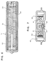
- the inflator can be any of a number of known constructions, including the passenger side inflator construction illustrated in U.S. Patent No. 4,296,084 to Schneiter, which patent is assigned to the assignee of the present invention.
- Fig. 6 is illustrative of an advanced passenger inflator which includes generally an outer housing 51 into which is inserted the wound filter unit 52 of this invention. An igniter 54 containing igniter material and the appropriate ignition system is then inserted into the central region of the inflator 50. While Fig. 6 shows loading the generant 53 directly into filter unit 52, a basket (not shown) can be used for holding the generant. The inflator is then sealed in a conventional manner known to those in the art.
- widths and wrap angles are given for illustration purpose only and are not limitations on the invention. Wire cloth widths from one to three inches and various wrapping angles are generally employed. Of course, the width and angle of the strips depends upon the desired configuration of the filter assembly. It is contemplated that the spiral wrap concept of the present invention could be used in manufacturing passenger, driver and side inflator systems.
- the spirally wrapped hollow cylindrical combustion filter assembly of the invention comprising at least one layer of filter media cut to the required length can be employed in a driver's side inflator for supporting the gas generant without the need for a perforated basket or additional convoluted filter layers.
- the hollow cylindrical combustion filter is coaxially arranged in the combustion chamber of the inflator and the gas generant is loaded in direct contact with the combustion filter. This construction would offer the same advantages in that there would be no bulges or bumps and this would allow the filter assembly to meet the close tolerances associated with driver side inflators.
- Fig. 7 illustrates such a driver-side inflator embodiment.
- Fig. 7 shows a driver side inflator 60 of general construction wherein the gas generant 61 is loaded into direct contact with the spirally wrapped combustion screen 62 of the present invention.
- the inflator 60 includes means comprising initiator 63 and igniter 64 for igniting gas generant 61.
- a driver side air bag inflator which could be used in practicing the present invention is disclosed in U.S. Patent No. 5,419,578, which is assigned to the assignee of the present invention.
Landscapes
- Chemical & Material Sciences (AREA)
- Chemical Kinetics & Catalysis (AREA)
- Engineering & Computer Science (AREA)
- Inorganic Chemistry (AREA)
- Life Sciences & Earth Sciences (AREA)
- Geology (AREA)
- Textile Engineering (AREA)
- Mechanical Engineering (AREA)
- Ceramic Engineering (AREA)
- Physics & Mathematics (AREA)
- Fluid Mechanics (AREA)
- Air Bags (AREA)
- Filtering Materials (AREA)
Applications Claiming Priority (2)
| Application Number | Priority Date | Filing Date | Title |
|---|---|---|---|
| US723458 | 1985-04-15 | ||
| US08/723,458 US5743560A (en) | 1996-10-09 | 1996-10-09 | Spiral wrapped inner tube for gas generator filter |
Publications (1)
| Publication Number | Publication Date |
|---|---|
| EP0839565A1 true EP0839565A1 (en) | 1998-05-06 |
Family
ID=24906356
Family Applications (1)
| Application Number | Title | Priority Date | Filing Date |
|---|---|---|---|
| EP97307962A Withdrawn EP0839565A1 (en) | 1996-10-09 | 1997-10-07 | Spiral wrapped inner tube for gas generating filter |
Country Status (3)
| Country | Link |
|---|---|
| US (1) | US5743560A (enExample) |
| EP (1) | EP0839565A1 (enExample) |
| JP (1) | JPH10128022A (enExample) |
Cited By (2)
| Publication number | Priority date | Publication date | Assignee | Title |
|---|---|---|---|---|
| WO2000026066A1 (en) * | 1998-11-04 | 2000-05-11 | Daicel Chemical Industries, Ltd. | Air bag gas generator and coolant therefor |
| CN112237808A (zh) * | 2020-04-08 | 2021-01-19 | 成都易态科技有限公司 | 滤管以及滤管的制备方法 |
Families Citing this family (16)
| Publication number | Priority date | Publication date | Assignee | Title |
|---|---|---|---|---|
| US6371484B1 (en) | 1998-07-27 | 2002-04-16 | Tsuan Yuan | Casino card game |
| US6065774A (en) * | 1998-10-15 | 2000-05-23 | Breed Automotive Technology, Inc. | Filtration system for gas generators |
| US6936311B2 (en) * | 1999-01-27 | 2005-08-30 | The United States Of America As Represented By The Secretary Of The Navy | Generation of biomaterial microarrays by laser transfer |
| FI107517B (fi) * | 1999-04-21 | 2001-08-31 | Tamfelt Oyj Abp | Menetelmä kutisteviiran valmistamiseksi ja kutisteviira |
| JP4776799B2 (ja) * | 2001-04-17 | 2011-09-21 | 富士フィルター工業株式会社 | 巻線型フィルター装置の製造方法 |
| US7287684B2 (en) * | 2002-07-03 | 2007-10-30 | Tubular Perforating Mfg., Ltd. | Filter cartridge assembly and method of manufacture |
| AU2003236406A1 (en) * | 2003-02-27 | 2005-03-10 | Tsuan Yuan | Casino card game (red & green) |
| US20070199889A1 (en) * | 2006-02-27 | 2007-08-30 | Ruediger Tueshaus | Tubular filter material assemblies and methods |
| US10717032B2 (en) * | 2006-09-21 | 2020-07-21 | Acs Industries, Inc. | Expanded metal filters |
| US9700825B2 (en) | 2006-09-21 | 2017-07-11 | Acs Industries, Inc. | Expanded metal filters |
| US7883112B2 (en) * | 2008-05-27 | 2011-02-08 | Autoliv Asp, Inc. | Textile gas guide for inflatable curtain |
| US8235415B2 (en) | 2010-08-31 | 2012-08-07 | Autoliv Asp, Inc. | Textile gas guides for use with inflatable cushions |
| US20140158609A1 (en) * | 2012-12-07 | 2014-06-12 | Porous Metal Filter | Sand Screen Filter for an Oil or Gas Well |
| US9434026B2 (en) * | 2014-10-02 | 2016-09-06 | Baker Hughes Incorporated | Subterranean screen assembly manufacturing method |
| US10676301B2 (en) * | 2017-02-03 | 2020-06-09 | Wallner Expac, Inc. | Expanded metal core |
| US12066041B2 (en) * | 2019-10-04 | 2024-08-20 | ZF Active Safety US Inc. | Coiled filter for hydraulic component |
Citations (7)
| Publication number | Priority date | Publication date | Assignee | Title |
|---|---|---|---|---|
| US4112159A (en) * | 1973-08-31 | 1978-09-05 | Pall Corporation | Continuous production of tubular modular filter elements using nonwoven webs from thermoplastic fibers and products |
| US5230726A (en) * | 1992-04-30 | 1993-07-27 | Morton International, Inc. | Spiral wrapped gas generator filter |
| US5407120A (en) * | 1994-05-25 | 1995-04-18 | Morton International, Inc. | Rotary swaging of gas generator filters |
| US5460721A (en) * | 1992-12-09 | 1995-10-24 | Goodwin; William R. | Helical wound tube |
| EP0694447A2 (en) * | 1994-07-26 | 1996-01-31 | Morton International, Inc. | Varying permeability filter for airbag inflator |
| US5551724A (en) * | 1993-09-14 | 1996-09-03 | Morton International, Inc. | Treatment of inflatable restraint system inflator particulate-containing gas with expanded metal |
| DE19540876A1 (de) * | 1995-11-02 | 1997-05-07 | Gessner & Co Gmbh | Mehrschichtige Separationseinheiten |
Family Cites Families (6)
| Publication number | Priority date | Publication date | Assignee | Title |
|---|---|---|---|---|
| US4296084A (en) * | 1979-10-29 | 1981-10-20 | Thiokol Corporation | Method of and apparatus for gas generation |
| JPH0478639A (ja) * | 1990-07-16 | 1992-03-12 | Asahi Chem Ind Co Ltd | エアバッグ用インフレータ |
| US5109772A (en) * | 1991-01-22 | 1992-05-05 | Morton International, Inc. | Flash ignition system |
| DE4201741A1 (de) * | 1992-01-23 | 1993-07-29 | Dynamit Nobel Ag | Filtervorrichtung zum filtern einer gasstroemung |
| JPH079939A (ja) * | 1993-06-22 | 1995-01-13 | Nippon Koki Kk | エアバッグ展開用ガス発生装置 |
| US5419578A (en) * | 1994-06-17 | 1995-05-30 | Morton International, Inc. | Inertia welded inflator |
-
1996
- 1996-10-09 US US08/723,458 patent/US5743560A/en not_active Expired - Fee Related
-
1997
- 1997-10-07 JP JP9274226A patent/JPH10128022A/ja active Pending
- 1997-10-07 EP EP97307962A patent/EP0839565A1/en not_active Withdrawn
Patent Citations (7)
| Publication number | Priority date | Publication date | Assignee | Title |
|---|---|---|---|---|
| US4112159A (en) * | 1973-08-31 | 1978-09-05 | Pall Corporation | Continuous production of tubular modular filter elements using nonwoven webs from thermoplastic fibers and products |
| US5230726A (en) * | 1992-04-30 | 1993-07-27 | Morton International, Inc. | Spiral wrapped gas generator filter |
| US5460721A (en) * | 1992-12-09 | 1995-10-24 | Goodwin; William R. | Helical wound tube |
| US5551724A (en) * | 1993-09-14 | 1996-09-03 | Morton International, Inc. | Treatment of inflatable restraint system inflator particulate-containing gas with expanded metal |
| US5407120A (en) * | 1994-05-25 | 1995-04-18 | Morton International, Inc. | Rotary swaging of gas generator filters |
| EP0694447A2 (en) * | 1994-07-26 | 1996-01-31 | Morton International, Inc. | Varying permeability filter for airbag inflator |
| DE19540876A1 (de) * | 1995-11-02 | 1997-05-07 | Gessner & Co Gmbh | Mehrschichtige Separationseinheiten |
Cited By (3)
| Publication number | Priority date | Publication date | Assignee | Title |
|---|---|---|---|---|
| WO2000026066A1 (en) * | 1998-11-04 | 2000-05-11 | Daicel Chemical Industries, Ltd. | Air bag gas generator and coolant therefor |
| CN112237808A (zh) * | 2020-04-08 | 2021-01-19 | 成都易态科技有限公司 | 滤管以及滤管的制备方法 |
| CN112237809A (zh) * | 2020-04-08 | 2021-01-19 | 成都易态科技有限公司 | 滤芯 |
Also Published As
| Publication number | Publication date |
|---|---|
| JPH10128022A (ja) | 1998-05-19 |
| US5743560A (en) | 1998-04-28 |
Similar Documents
| Publication | Publication Date | Title |
|---|---|---|
| US5743560A (en) | Spiral wrapped inner tube for gas generator filter | |
| US5230726A (en) | Spiral wrapped gas generator filter | |
| US5673483A (en) | Method for constructing an inflator filter made of wrapped mesh | |
| US5308370A (en) | Filter device for filtering a gas flow | |
| US5702494A (en) | Airbag filter assembly and method of assembly thereof | |
| US7559146B2 (en) | Wire mesh filter with improved hoop strength | |
| JP3973814B2 (ja) | エアバッグインフレーター用フィルター、およびその製造方法 | |
| CN100411920C (zh) | 用于气囊气体发生器的过滤器 | |
| WO2008143606A1 (en) | Wound wire filter elements | |
| US20100146922A1 (en) | Wound Wire Filter Elements | |
| JPH10128022A5 (enExample) | ||
| EP1732788A2 (en) | Inflator and method of assembly | |
| US5407120A (en) | Rotary swaging of gas generator filters | |
| JP4370177B2 (ja) | インフレータ用濾過部材及びインフレータ用濾過部材の製造方法 | |
| US5816612A (en) | Air bag inflator | |
| JP3992267B2 (ja) | エアバック装置のインフレータ用フィルタ | |
| US7449042B2 (en) | Filtering member and method of manufacturing the same | |
| JP4402705B2 (ja) | エアバッグインフレーター用フィルター、およびその製造方法 | |
| US5346252A (en) | Inflator and method of assembly | |
| JP5848914B2 (ja) | エアバッグインフレーター用フィルター及びその製造方法 | |
| CN101522282A (zh) | 卷绕金属丝过滤器元件 | |
| EP2032232A1 (en) | Wound wire filter elements | |
| JPH07309192A (ja) | 円筒状のインフレーター用フイルターとその製造方法 | |
| US8746147B1 (en) | Filter for gas generating system | |
| MXPA97009387A (en) | Assembly of air bag filter and mi assembly method |
Legal Events
| Date | Code | Title | Description |
|---|---|---|---|
| PUAI | Public reference made under article 153(3) epc to a published international application that has entered the european phase |
Free format text: ORIGINAL CODE: 0009012 |
|
| AK | Designated contracting states |
Kind code of ref document: A1 Designated state(s): AT BE CH DE DK ES FI FR GB GR IE IT LI LU MC NL PT SE |
|
| AX | Request for extension of the european patent |
Free format text: AL;LT;LV;RO;SI |
|
| AKX | Designation fees paid | ||
| RBV | Designated contracting states (corrected) | ||
| STAA | Information on the status of an ep patent application or granted ep patent |
Free format text: STATUS: THE APPLICATION IS DEEMED TO BE WITHDRAWN |
|
| 18D | Application deemed to be withdrawn |
Effective date: 19981107 |