EP0838955B1 - Videokodierungs- und Videodekodierungsvorrichtung - Google Patents
Videokodierungs- und Videodekodierungsvorrichtung Download PDFInfo
- Publication number
- EP0838955B1 EP0838955B1 EP19970111543 EP97111543A EP0838955B1 EP 0838955 B1 EP0838955 B1 EP 0838955B1 EP 19970111543 EP19970111543 EP 19970111543 EP 97111543 A EP97111543 A EP 97111543A EP 0838955 B1 EP0838955 B1 EP 0838955B1
- Authority
- EP
- European Patent Office
- Prior art keywords
- resolution
- picture
- block
- prediction
- coding
- Prior art date
- Legal status (The legal status is an assumption and is not a legal conclusion. Google has not performed a legal analysis and makes no representation as to the accuracy of the status listed.)
- Expired - Lifetime
Links
Images


Classifications
-
- H—ELECTRICITY
- H04—ELECTRIC COMMUNICATION TECHNIQUE
- H04N—PICTORIAL COMMUNICATION, e.g. TELEVISION
- H04N19/00—Methods or arrangements for coding, decoding, compressing or decompressing digital video signals
- H04N19/50—Methods or arrangements for coding, decoding, compressing or decompressing digital video signals using predictive coding
- H04N19/59—Methods or arrangements for coding, decoding, compressing or decompressing digital video signals using predictive coding involving spatial sub-sampling or interpolation, e.g. alteration of picture size or resolution
-
- H—ELECTRICITY
- H04—ELECTRIC COMMUNICATION TECHNIQUE
- H04N—PICTORIAL COMMUNICATION, e.g. TELEVISION
- H04N19/00—Methods or arrangements for coding, decoding, compressing or decompressing digital video signals
- H04N19/10—Methods or arrangements for coding, decoding, compressing or decompressing digital video signals using adaptive coding
- H04N19/102—Methods or arrangements for coding, decoding, compressing or decompressing digital video signals using adaptive coding characterised by the element, parameter or selection affected or controlled by the adaptive coding
- H04N19/103—Selection of coding mode or of prediction mode
- H04N19/105—Selection of the reference unit for prediction within a chosen coding or prediction mode, e.g. adaptive choice of position and number of pixels used for prediction
-
- H—ELECTRICITY
- H04—ELECTRIC COMMUNICATION TECHNIQUE
- H04N—PICTORIAL COMMUNICATION, e.g. TELEVISION
- H04N19/00—Methods or arrangements for coding, decoding, compressing or decompressing digital video signals
- H04N19/10—Methods or arrangements for coding, decoding, compressing or decompressing digital video signals using adaptive coding
- H04N19/102—Methods or arrangements for coding, decoding, compressing or decompressing digital video signals using adaptive coding characterised by the element, parameter or selection affected or controlled by the adaptive coding
- H04N19/117—Filters, e.g. for pre-processing or post-processing
-
- H—ELECTRICITY
- H04—ELECTRIC COMMUNICATION TECHNIQUE
- H04N—PICTORIAL COMMUNICATION, e.g. TELEVISION
- H04N19/00—Methods or arrangements for coding, decoding, compressing or decompressing digital video signals
- H04N19/10—Methods or arrangements for coding, decoding, compressing or decompressing digital video signals using adaptive coding
- H04N19/134—Methods or arrangements for coding, decoding, compressing or decompressing digital video signals using adaptive coding characterised by the element, parameter or criterion affecting or controlling the adaptive coding
- H04N19/136—Incoming video signal characteristics or properties
- H04N19/137—Motion inside a coding unit, e.g. average field, frame or block difference
- H04N19/139—Analysis of motion vectors, e.g. their magnitude, direction, variance or reliability
-
- H—ELECTRICITY
- H04—ELECTRIC COMMUNICATION TECHNIQUE
- H04N—PICTORIAL COMMUNICATION, e.g. TELEVISION
- H04N19/00—Methods or arrangements for coding, decoding, compressing or decompressing digital video signals
- H04N19/10—Methods or arrangements for coding, decoding, compressing or decompressing digital video signals using adaptive coding
- H04N19/134—Methods or arrangements for coding, decoding, compressing or decompressing digital video signals using adaptive coding characterised by the element, parameter or criterion affecting or controlling the adaptive coding
- H04N19/146—Data rate or code amount at the encoder output
- H04N19/152—Data rate or code amount at the encoder output by measuring the fullness of the transmission buffer
-
- H—ELECTRICITY
- H04—ELECTRIC COMMUNICATION TECHNIQUE
- H04N—PICTORIAL COMMUNICATION, e.g. TELEVISION
- H04N19/00—Methods or arrangements for coding, decoding, compressing or decompressing digital video signals
- H04N19/10—Methods or arrangements for coding, decoding, compressing or decompressing digital video signals using adaptive coding
- H04N19/134—Methods or arrangements for coding, decoding, compressing or decompressing digital video signals using adaptive coding characterised by the element, parameter or criterion affecting or controlling the adaptive coding
- H04N19/157—Assigned coding mode, i.e. the coding mode being predefined or preselected to be further used for selection of another element or parameter
- H04N19/159—Prediction type, e.g. intra-frame, inter-frame or bidirectional frame prediction
-
- H—ELECTRICITY
- H04—ELECTRIC COMMUNICATION TECHNIQUE
- H04N—PICTORIAL COMMUNICATION, e.g. TELEVISION
- H04N19/00—Methods or arrangements for coding, decoding, compressing or decompressing digital video signals
- H04N19/10—Methods or arrangements for coding, decoding, compressing or decompressing digital video signals using adaptive coding
- H04N19/169—Methods or arrangements for coding, decoding, compressing or decompressing digital video signals using adaptive coding characterised by the coding unit, i.e. the structural portion or semantic portion of the video signal being the object or the subject of the adaptive coding
- H04N19/17—Methods or arrangements for coding, decoding, compressing or decompressing digital video signals using adaptive coding characterised by the coding unit, i.e. the structural portion or semantic portion of the video signal being the object or the subject of the adaptive coding the unit being an image region, e.g. an object
- H04N19/176—Methods or arrangements for coding, decoding, compressing or decompressing digital video signals using adaptive coding characterised by the coding unit, i.e. the structural portion or semantic portion of the video signal being the object or the subject of the adaptive coding the unit being an image region, e.g. an object the region being a block, e.g. a macroblock
-
- H—ELECTRICITY
- H04—ELECTRIC COMMUNICATION TECHNIQUE
- H04N—PICTORIAL COMMUNICATION, e.g. TELEVISION
- H04N19/00—Methods or arrangements for coding, decoding, compressing or decompressing digital video signals
- H04N19/10—Methods or arrangements for coding, decoding, compressing or decompressing digital video signals using adaptive coding
- H04N19/189—Methods or arrangements for coding, decoding, compressing or decompressing digital video signals using adaptive coding characterised by the adaptation method, adaptation tool or adaptation type used for the adaptive coding
- H04N19/196—Methods or arrangements for coding, decoding, compressing or decompressing digital video signals using adaptive coding characterised by the adaptation method, adaptation tool or adaptation type used for the adaptive coding being specially adapted for the computation of encoding parameters, e.g. by averaging previously computed encoding parameters
-
- H—ELECTRICITY
- H04—ELECTRIC COMMUNICATION TECHNIQUE
- H04N—PICTORIAL COMMUNICATION, e.g. TELEVISION
- H04N19/00—Methods or arrangements for coding, decoding, compressing or decompressing digital video signals
- H04N19/50—Methods or arrangements for coding, decoding, compressing or decompressing digital video signals using predictive coding
- H04N19/503—Methods or arrangements for coding, decoding, compressing or decompressing digital video signals using predictive coding involving temporal prediction
- H04N19/51—Motion estimation or motion compensation
- H04N19/527—Global motion vector estimation
-
- H—ELECTRICITY
- H04—ELECTRIC COMMUNICATION TECHNIQUE
- H04N—PICTORIAL COMMUNICATION, e.g. TELEVISION
- H04N19/00—Methods or arrangements for coding, decoding, compressing or decompressing digital video signals
- H04N19/60—Methods or arrangements for coding, decoding, compressing or decompressing digital video signals using transform coding
- H04N19/61—Methods or arrangements for coding, decoding, compressing or decompressing digital video signals using transform coding in combination with predictive coding
-
- H—ELECTRICITY
- H04—ELECTRIC COMMUNICATION TECHNIQUE
- H04N—PICTORIAL COMMUNICATION, e.g. TELEVISION
- H04N19/00—Methods or arrangements for coding, decoding, compressing or decompressing digital video signals
- H04N19/80—Details of filtering operations specially adapted for video compression, e.g. for pixel interpolation
- H04N19/82—Details of filtering operations specially adapted for video compression, e.g. for pixel interpolation involving filtering within a prediction loop
-
- H—ELECTRICITY
- H04—ELECTRIC COMMUNICATION TECHNIQUE
- H04N—PICTORIAL COMMUNICATION, e.g. TELEVISION
- H04N19/00—Methods or arrangements for coding, decoding, compressing or decompressing digital video signals
- H04N19/85—Methods or arrangements for coding, decoding, compressing or decompressing digital video signals using pre-processing or post-processing specially adapted for video compression
- H04N19/86—Methods or arrangements for coding, decoding, compressing or decompressing digital video signals using pre-processing or post-processing specially adapted for video compression involving reduction of coding artifacts, e.g. of blockiness
Definitions
- the present invention relates to video coding apparatus and video decoding apparatus, and more particularly, to a video coding apparatus that performs predictive coding of digital video signals and a video decoding apparatus that reproduces the original motion images from the predictive-coded video signal produced by the video coding apparatus.
- the ITU-T standard H.261 and the ISO standards MPEG-1 and MPEG-2, for example, are well-acknowledged international standards for motion picture coding techniques.
- Those standards use hybrid coding algorithms, where the coding process will proceed as follows: (1) a source picture is divided into blocks of pixels, (2) orthogonal transformation (e.g., discrete cosine transform) and motion compensation are applied independently on each block, and (3) quantized video data is compressed by entropy coding.
- the above-described hybrid video coding techniques may suffer from an overwhelming amount of coded frame data that exceeds a certain standard level allowed for each frame.
- the coder will forcibly reduce the amount of coded data in an attempt to regulate it at the standard level. This will cause extreme degradation in image quality and coarse frame subsampling (or a drop in frame update rates), thus resulting in unacceptably poor pictures when reconstructed at the receiving ends.
- a video coding system aiming at avoidance of the above problem is proposed in Japanese Patent Application No. 8-75605 (1996), for instance, by the same applicant of the present invention.
- the video coding apparatus reduces the resolution of input frame signals to regulate the amount of coded frame data when a full scene transition or a massive motion has happened in the middle of a sequence of video frames.
- FIG. 14 is a block diagram of this video coding apparatus proposed in the Japanese Patent Application No. 8-75605.
- the apparatus of FIG. 14 supports two kinds of picture resolutions: Common Intermediate Format (CIF, 352 x 288 pixels) and quarter-CIF (QCIF, 176 x 144 pixels).
- CIF/QCIF selection controller 125 determines which picture resolution should be used to encode source pictures, considering the amount of coded frame data produced in a predictive coding, quantizer step size, and some other parameters. For example, the CIF/QCIF selection controller 125 normally chooses the high resolution CIF, while it chooses the low resolution QCIF when a large amount of data has been produced as a result of the coding.
- a frame memory 122 is used to store reconstructed (or decoded) pictures of the previous frames. Comparing the source picture of the current frame with a decoded picture that is retrieved from the frame memory 122 as the reference picture, a prediction parameter calculation unit 112 computes motion vectors of the current frame. Here, a picture is partitioned into a plurality of blocks and the comparison of frame data is performed on a block-by-block basis. Each source frame picture is subjected to either an intraframe coding or an interframe coding. A prediction parameter calculation unit 112 determines which coding scheme should be applied to the source frame picture. When the interframe coding is activated, a prediction picture generation unit 113 produces a prediction picture of the current frame based on the decoded image of the previous frame and the motion vectors calculated by the prediction parameter calculation unit 112.
- a prediction error signal generation unit 114 produces a prediction error signal by calculating differences between the source picture and the prediction picture on a block-by-block basis.
- a CIF/QCIF converter 131 changes the resolution of this prediction error signal, which is originally CIF, to what is chosen by the CIF/QCIF selection controller 125. More specifically, the CIF/QCIF converter 131 outputs the prediction error signal as it is when the CIF resolution is selected by the CIF/QCIF selection controller 125, and it in turn converts the resolution to QCIF when the QCIF resolution is selected.
- a coding controller 124 receives information regarding the amount of the resultant coded data from an entropy coding unit 117 (described later), as well as obtaining information on buffer occupancy from a coded data buffer 118 (described later). Based on such information, the coding controller 124 determines the quantizer step size and distributes it to a quantizer 116, a dequantizer 119, the CIF/QCIF selection controller 125, and the entropy coder 117.
- a DCT processor 115 applies an orthogonal transform, or a digital cosine transform (DCT), to the output of the CIF/QCIF converter 131, and a quantizer 116 quantizes the obtained DCT coefficients in accordance with the quantizer step size specified by the coding controller 124.
- DCT digital cosine transform
- the entropy coder 117 receives the quantized DCT coefficients from the quantizer 116, the picture resolution from the CIF/QCIF selection controller 125, and the motion vectors and coding scheme information from the prediction parameter calculation unit 112.
- Entropy coding is a data compression process that assigns shorter code words to frequent events and longer code words to less frequent events. Out of a predefined code word table, the entropy coder 117 retrieves code words relevant to each combination of the above received data, thereby outputting the coded frame data.
- the quantized DCT coefficients produced by the quantizer 116 are also supplied to the dequantizer 119 for inverse quantization, or dequantization.
- the resultant output signals are then subjected to an inverse discrete cosine transform (IDCT) process that is executed by an IDCT processor 120 to reproduce the original prediction error signal.
- IDCT inverse discrete cosine transform
- a QCIF/CIF converter 132 reconverts it to regain the original CIF resolution.
- a decoded picture generator 121 reconstructs a picture by adding the prediction error signal outputted by the QCIF/CIF converter 132 to the prediction picture produced by the prediction picture generator 113. This fully decoded picture is then transferred to a frame memory 122 for storage.
- the proposed video coding apparatus monitors the amount of coded frame data and the like, and if any significant increase is expected in the amount of coded frame data, the apparatus will reduce the resolution of the prediction error signal from CIF to QCIF.
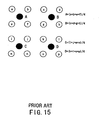
- the CIF/QCIF converter 131 performs such resolution reduction through a downsampling process as exemplified in FIG. 15. More specifically, white dots in FIG. 15 represent CIF pixels and lower-case alphabetic characters placed in them indicate their respective prediction error signal values. Black dots represent QCIF pixels, and upper-case letters beside them signify their respective prediction error signal values.
- the QCIF/CIF converter 132 performs a QCIF-to-CIF resolution conversion through an upsampling process as shown in FIG. 16. More specifically, black dots represent QCIF pixels, and upper-case letters beside them indicate their respective prediction error signal values, while white dots represent CIF pixels and lower-case letters in them indicate their respective prediction error signal values. To obtain the CIF prediction error signal values a, b, c , and so on, the upsampling process calculates a weighted average value of four QCIF pixels surrounding each CIF pixel.
- the above-described conventional video coding apparatus is constructed on the assumption that all blocks in a frame are encoded by using a consistent coding scheme. More specifically, it is assumed that every block in a given frame is subjected to either an intraframe coding or an interframe coding, but this coding scheme cannot be switched in the middle of the frame.
- a dashed line 133 represents a block boundary where the applied coding scheme changes from interframe coding to intraframe coding or vise versa.
- FIG. 17 schematically shows a process of the predictive coding and decoding of a source picture.
- FIG. 17 consists of six graphs, (a) to (f), each of which represents how the pixel values will vary when scanning across some different blocks.
- these graphs show the profiles of pixel values in the neighborhood of a certain block boundary. More specifically, the left half of each profile (labeled "Intra”) is a block subject to the intraframe coding, while the right half (labeled "Inter”) is a block subject to the interframe coding, where the vertical dashed line indicates the block boundary.
- the upper-left graph (a) shows the profile of a source picture, in which the pixel values are just flat in both blocks.
- the left block Since the left block is subjected to the intraframe coding and thus has no reference frame for prediction, its pixel values in the prediction picture profile (b) will be zeros. Accordingly, the resultant prediction error signal (c) exhibits large difference values in the left block, while showing small values in the right block that is subject to the interframe coding.
- the big "+" and “-” signs imply subtraction and addition of pictures, respectively.
- the upsampling operations executed by the QCIF/CIF converter 132 as noted earlier will introduce a mixture of differently coded pixel values in the vicinity of the block boundary. That is, the reproduced prediction error signal will be deformed as illustrated in a profile (d) of FIG. 17, as a result of the upsampling operations by the QCIF/CIF converter 132. Then the summation of this reproduced prediction error signal (d) and a prediction picture (e), which equals the prediction picture (b), provided from the prediction picture generation unit 113 will yield a decoded picture (f). As illustrated in FIG.
- the resultant decoded picture (f) contains some distortion in the vicinity of the block boundary. Fidelity of decoded pictures to the original pictures is one of the important design considerations in video decoders. As opposed to this, the picture (f) reconstructed by the conventional video coding apparatus is different from the original source picture (a).
- This kind of problem may occur not only in the particular situation in which two different coding schemes are applied to adjacent blocks in a frame, but it can potentially happen to any video frames that contain some sharp edges exhibiting a large difference or discontinuity in pixel values at a certain block boundary in a single frame. Such discontinuous transitions of pixel values may also be observed in such video frames where two neighboring blocks have quite different motion vectors. When decoded, the picture will suffer from similar noises, or artifacts, produced in the vicinity of the boundary of those neighboring blocks. Further, reference is made to up sampling documents EP-A-589 504 and WO-A-96/17478.
- an object of the present invention is to provide a video coding apparatus and a video decoding apparatus which can reproduce decoded pictures without introducing unwanted noises, even if any considerable difference in pixel values or discontinuity exists at a certain block boundary.
- a video coding apparatus for performing a predictive coding of digital video input signals.
- the apparatus comprises: (a) resolution determination means for selecting a picture resolution to be used in a video coding of a source picture of a current frame, the picture resolution being either a low resolution or a high resolution; (b) decoded picture storage means for storing a past decoded picture reproduced in a previous frame; (c) prediction parameter calculation means, coupled to the resolution determination means, for determining which of two coding schemes should be used to encode individual blocks, by comparing the source picture of the current frame with the past decoded picture stored in the decoded picture storage means, and also for calculating motion vectors of the blocks in the source picture, wherein the two coding schemes include an intraframe coding and an interframe coding, and the blocks are defined by partitioning a given picture into pieces according to the picture resolution determined by the resolution determination means; (d) prediction picture generation means for producing a prediction picture through calculation of pixel values on a block-by-block basis
- This apparatus comprises: (a) resolution determination means for selecting a picture resolution to be used in a video coding of a source picture of a current frame, the picture resolution being either a low resolution or a high resolution; (b) decoded picture storage means for storing a past decoded picture reproduced in a previous frame; (c) prediction parameter calculation means, coupled to the resolution determination means, for determining which of two coding schemes should be used to encode individual blocks, by comparing the source picture of the current frame with the past decoded picture stored in the decoded picture storage means, and also for calculating motion vectors of the blocks in the source picture, wherein the two coding schemes include an intraframe coding and an interframe coding, and the blocks are defined by partitioning a given picture into pieces according to the picture resolution determined by the resolution determination means; (d) prediction picture generation means for producing a prediction picture through calculation of pixel values on a block-by-block basis
- This first embodiment is specifically related to a video coding apparatus.
- the first embodiment of the present invention proposes a video coding apparatus which comprises the following elements.
- the resolution determination means 1 determines the picture resolution at which a source picture is to be coded. More specifically, the resolution determination means 1 selects a high resolution when the code allocation unit 8 have produced a smaller amount of coded data than a predetermined standard volume. It selects in turn a low resolution when the amount of the coded data is larger than the standard code volume.
- the prediction parameter calculation means 3 For each block defined by partitioning the source picture according to the picture resolution determined by the resolution determination means 1, the prediction parameter calculation means 3 performs computation of a motion vector, as well as determining which coding scheme (i.e., intraframe or interframe) should be applied to the block.
- the prediction picture generation means 4 produces a prediction picture on a block-by-block basis, according to the output of the prediction parameter calculation means 3. That is, when the intraframe coding is applied to a certain block, the prediction picture generation means 4 outputs zeros for the pixel values of the block of interest as part of the prediction picture in process.
- the prediction picture generation means 4 produces a prediction picture of the block by applying the calculated motion vector to the relevant data retrieved from the decoded picture storage means 2 which stores the reconstructed pictures in some previous frames.
- the prediction error signal generation means 5 produces a prediction error signal by calculating differences between the current frame picture and the prediction picture on a block-by-block basis.
- the produced prediction error signal is then subjected to the first resolution conversion means 6 for reduction of the picture resolution if it is required by the resolution determination means 1. More specifically, the first resolution conversion means 6 forwards the prediction error signal as is when the high resolution is selected by the resolution determination means 1, and it converts the picture resolution of the signal down to the low resolution when the low resolution is selected by the resolution determination means 1.
- the orthogonal transformation/quantization means 7 applies an orthogonal transformation and quantization processes to the output of the first resolution conversion means 6.
- the code allocation means 8 receives at least the output signal of the orthogonal transformation/quantization means 7, the picture resolution determined by the resolution determination means 1, and the coding scheme and motion vectors obtained by the prediction parameter calculation means 3. Some appropriate code words to represent various combinations of those kinds of data are prepared in a code word table. The code allocation means 8 retrieves such code words relevant to the received data and transmits them to the receiving ends via a transmission channel.
- the dequantization/inverse orthogonal transformation means 9 dequantizes the output signal of the orthogonal transformation/quantization means 7, and it further executes an inverse orthogonal transformation to reproduce the prediction error signal as originally generated.
- the first resolution conversion means 6 has subsampled the original prediction error signal to reduce its resolution
- the reproduced prediction error signal will, of course, have the reduced picture resolution.
- the second resolution conversion means 10 attempts to restore the original resolution by performing an upsampling process in the way described earlier. Recall that this upsampling process is a process to obtain the high-resolution pixel values from the values of some surrounding low-resolution pixels.
- the upsampling process will not refer to the pixels belonging to any adjacent block that is subject to another coding scheme which is different from that applied to the present block.
- the upsampling process can be implemented so that it will neglect the pixels in other blocks but will refer only to the present block of interest.
- the present invention prevents the difference in coding schemes from affecting the reproduced prediction error signal, as opposed to the conventional upsampling process where the blocks with different coding schemes cause some unwanted noises in the reproduced signal as illustrated in the profile (d) of FIG. 17.
- the reproduced prediction error signal outputted by the second resolution conversion means 10 will have the original signal form as shown in the profile (c).
- the above-described resolution conversion will not be executed when the first resolution conversion means 6 did not downsample the original prediction error signal. In that case, the second resolution conversion means 10 forwards the reproduced prediction error signal as is.
- the decoded picture generation means 11 reconstructs a picture by adding the reproduced prediction error signal sent from the second resolution conversion means 10 to the prediction picture produced by the prediction picture generation means 4.
- the resultant picture, or decoded picture is then supplied to the decoded picture storage means 2.
- the present invention can reproduce the motion pictures without introducing unwanted noises, even if some mixed coding schemes are used for encoding a frame, or in other words, even if two adjacent blocks exhibit a big difference in pixel values.
- FIG. 3 is a block diagram showing a specific structure of the first embodiment of the present invention.
- a resolution selection controller 21 which corresponds to the resolution determination means 1 in FIG. 1, receives the quantizer step size from a control unit 33 (described later). It also receives the amount of coded frame data from an entropy coder 28, and the buffer occupancy information from a coded data buffer 34. Based on all the received information, the resolution selection controller 21 determines an appropriate picture resolution for each frame, so that the video information delivered to the receiving ends will not suffer from intolerable image quality degradation due to the coarse subsampling of frames. In the first embodiment, the resolution selection controller 21 normally chooses a high resolution of 352 x 288 pixels, or the CIF resolution.
- the resolution selection controller 21 can be configured, as an alternative arrangement, such that it will switch three or more kinds of resolutions.
- the aforementioned Japanese Patent Application No. 8-75605 (1996), for example, provides some detailed description.
- Notification of the determined resolution is sent to a downsampling switch 26b, a lowpass filter switch 32b, a prediction parameter calculator 23, and an upsampling switch 30b as described later. It is also supplied to an entropy coder 28 although the signal flow is not illustrated in FIG. 3.
- a frame memory 22, serving as the decoded picture storage means 2 in FIG. 1, is used to store picture data of one or more frames reconstructed in the past few coding cycles.
- a prediction parameter calculator 23 is what is described as the prediction parameter calculation means 3 in FIG. 1. For each block obtained by partitioning the source picture according to the picture resolution determined by the resolution selection controller 21, the prediction parameter calculator 23 calculates a motion vector, as well as determining the coding scheme (i.e., intraframe or interframe) to be applied. The size of each block depends on the resolution determined by the resolution selection controller 21. It is either 16 ⁇ 16 pixels for CIF resolution or 32 ⁇ 32 pixels for QCIF resolution.
- the information about the determined coding scheme is sent to the prediction picture switch 24b and the upsampling unit 30a, while the calculated motion vector of each block is supplied to the lowpass filter switch 32b and the entropy coder 28.
- a prediction picture generator 24a and prediction picture switch 24b serve as the prediction picture generation means 4 shown in FIG. 1.
- the prediction picture generator 24a retrieves a relevant past decoded picture from the frame memory 22 and then applies the motion vectors sent from the prediction parameter calculation unit 23 to the retrieved picture to construct a prediction picture of the current frame.
- the prediction picture switch 24b is a switch to control the content of the prediction pictures on a block-by-block basis, in accordance with the coding scheme specified by the prediction parameter calculator 23. More specifically, the prediction picture switch 24b outputs zeros for the predicted pixel values when the block is subjected to the intraframe coding. It, in turn, selects the prediction picture output of the prediction picture generator 24a when the interframe coding is specified.
- a lowpass filter 32a removes high-frequency components contained in each predicted block. Based on each block's motion vector sent from the prediction parameter calculator 23, a lowpass filter switch 32b examines how fast each block is moving, thereby classifying the blocks into two groups: fast-motion group and less-motion group. The lowpass filter switch 32b further uses the picture resolution provided by the resolution selection controller 21 to determine whether or not to activate the high-frequency components. More specifically, when the QCIF resolution is specified and the block of interest falls into the fast-motion group, the lowpass filter switch 32b selects the output of the lowpass filter 32a. On the other hand, when the QCIF resolution is specified but the block falls into the less-motion group, or when the CIF resolution is specified, the lowpass filter switch 32b will bypass the lowpass filter 32a.
- the frequency response of a predictive coding process is subject to the Nyquist bandwidth limitation. That is, when operating with the QCIF picture format, the coding process is unable to encode the frequency components beyond the Nyquist frequency ( ⁇ 1) defined by the QCIF resolution. The higher-frequency components beyond ⁇ 1, if exist, could cause some coding errors to accumulate in the coding loop, resulting in a deterioration in the quality of pictures with the passage of time. It is therefore necessary to remove such unwanted higher-frequency components from the prediction picture to prevent the coding error from accumulating, and this is why the lowpass filter 32a is incorporated in the video coding apparatus of the present invention.
- a picture generally consists of areas exhibiting relatively slow or no motions (e.g., background image) and areas containing fast motions (e.g., actor or actress). If the above-described low-pass filter is applied to the blocks in less active areas, the resultant high-frequency suppression will spoil the sharpness of the picture in those areas. Since there is, of course, no need to further reduce the picture information in such less active areas that can be coded at a high compression ratio, the high-frequency suppression should not be applied to them.
- a prediction error signal generation unit 25 serves as the prediction error signal generation means 5 in FIG. 1.
- the combination of a downsampling unit 26a and downsampling switch 26b corresponds to the first resolution conversion means 6 in FIG. 1.
- the prediction error signal produced by the prediction error signal generation unit 25 for each block is supplied to the downsampling unit 26a to apply a downsampling process as described earlier with reference to FIG. 15.
- the downsampling switch 26b is used to bypass the downsampling process for the prediction error signal, depending on the picture resolution received from the resolution selection controller 21. For the blocks where the CIF resolution is specified, it selects the direct output of the prediction error signal generation unit 25, and for the blocks where the QCIF resolution is specified, it chooses the output of the downsampling unit 26a.
- the orthogonal transformation/quantization means 7 in FIG. 1 is implemented as a combination of a DCT processor (8 ⁇ 8 DCT) 27a and quantizer 27b.
- the DCT processor 27a performs a discrete cosine transform for every 8 ⁇ 8 pixel block, thereby yielding a set of transform coefficients.
- the quantizer 27b quantizes the transform coefficients according to the quantizer step size sent from the coding controller 33 (described later). The obtained values are referred to as quantized coefficients.
- the coding controller 33 receives information on the amount of the resultant coded data from an entropy coder 28 (described later), as well as being informed of the buffer occupancy by a coded data buffer 34. Based on those two kinds of information, the coding controller 33 determines and distributes the quantizer step size to the quantizer 27b, dequantizer 29a, resolution selection controller 29a, and entropy coder 28.
- the coded data buffer 34 serves as temporary storage for the coded frame data produced by the entropy coder 28.
- a dequantizer 29a and an IDCT processor (8 ⁇ 8 IDCT) 29b work as the dequantization/inverse orthogonal transformation means 9 in FIG. 1.
- An upsampling unit 30a and an upsampling switch 30b operate in combination as the second resolution conversion means 10 in FIG. 1.
- the upsampling unit 30a When attempting to process a block in a certain coding scheme determined by the prediction parameter calculator 23, the upsampling unit 30a first examines whether or not the block of interest is adjacent to any blocks being subject to the different coding scheme. If such a neighboring block is found, the upsampling unit 30a will convert the block of interest to increase the resolution by upsampling the pixels.
- the upsampling algorithm used in this case will be described later with reference to FIG. 4.
- the upsampling unit 30a performs a conventional upsampling process as illustrated in FIG. 16.
- the upsampling switch 30b allows the reproduced prediction error signal to bypass the upsampling process, depending on the picture resolution received from the resolution selection controller 21. For the blocks where the CIF resolution is specified, it selects the exact output of the IDCT processor 29b, and for the blocks where the QCIF resolution is specified, it chooses the output of the upsampling unit 30a. As a result, the reproduced prediction error signal supplied to the next stage will consistently have the CIF resolution.
- FIG. 4 depicts the above upsampling process performed by the upsampling unit 30a.
- black dots represent QCIF pixels, and upper-case alphabetical characters are affixed to them to indicate their respective prediction error signal levels.
- white dots represent CIF pixels, and lower-case letters indicate their respective prediction error signal levels.
- the prediction error signal values at the pixels located immediately adjacent to the block boundary 36 are calculated by the upsampling unit 30a, considering only two neighboring QCIF pixels, or without referring to the pixels beyond the block boundary 36 which are subject to the different coding scheme.
- the present invention prevents the difference in coding schemes from affecting the reproduced prediction error signal, as opposed to the conventional upsampling process where the blocks with different coding schemes may cause some undesired noises in the reproduced prediction error signal as illustrated in the signal profile (d) of FIG. 17.
- the reproduced prediction error signal appearing at the output of the upsampling unit 30a will exhibit a near-original signal profile as shown in the signal profile (c).
- the present invention can reproduce the original pictures without introducing noises, even if some mixed coding schemes are used for compressing a frame, or even if there exists a considerable difference in pixel values at a certain block boundary.
- the proposed upsampling unit 30a examines whether or not the block of interest is adjacent to any other block being subject to the different coding scheme, and if such a neighboring block is found, it will upsample the pixels using the algorithm explained in FIG. 4.
- FIG. 5 is a block diagram showing the structure of the second embodiment of the present invention. Since the second embodiment has basically the same structure as that of the first embodiment, the following description will focus on its distinctive points, while affixing like reference numerals to like elements.
- the second embodiment is distinguishable in that an 8 ⁇ 8 DCT processor 38, a 16 ⁇ 16 DCT processor 39, an extraction unit 40, and a selector 41 are introduced in place of the downsampling unit 26a, downsampling switch 26b, and DCT processor 27a of the first embodiment.
- the second embodiment effectively uses the similarity between a 16 ⁇ 16 orthogonal transform and an 8 ⁇ 8 orthogonal transform in their bases. More specifically, the 16 ⁇ 16 DCT processor 39 applies a 16 ⁇ 16 orthogonal transform to the prediction error signal with CIF format, and the extraction unit 40 extracts the low-frequency components out of the obtained transform coefficients.
- the 8 ⁇ 8 DCT processor 38 disposed in parallel with the 16 ⁇ 16 DCT processor 39 and extraction unit 40, applies an 8 ⁇ 8 orthogonal transform to the same prediction error signal.
- the selector 41 selects either set of transform coefficients, depending on the picture resolution received from the resolution selection controller 21. For the blocks where the CIF resolution is specified, the selector 41 chooses the output of the 8 ⁇ 8 DCT processor 38, and for the blocks where the QCIF resolution is specified, it in turn chooses the output of the extraction unit 40. The quantizer 27b then receives the set of transform coefficients that was selected.
- the second embodiment will greatly reduce the amount of computation loads in comparison to the first embodiment.
- FIG. 6 is a block diagram showing a specific structure of the third embodiment of the present invention. Since the third embodiment has basically the same structure as that of the first embodiment, the following description will focus on its distinctive points, while affixing like reference numerals to like elements.
- the third embodiment is distinguishable from the first embodiment in that an 8 ⁇ 8 IDCT processor 42, an assignment unit 43, a 16 ⁇ 16 IDCT processor 44, and a selector 45 are introduced in place of the upsampling unit 30a, upsampling switch 30b, and IDCT processor 29b of the first embodiment.
- the third embodiment uses the similarity between a 16 ⁇ 16 orthogonal transform and an 8 ⁇ 8 orthogonal transform in terms of the transform basis. More specifically, the coefficient assignment unit 43 regards the dequantized 8 ⁇ 8 transform coefficients sent from the dequantizer 29a as 8 ⁇ 8 low-frequency components as part of a 16 ⁇ 16 transform coefficient block. The coefficient assignment unit 43 further assigns zeros to the remaining transform coefficients.
- the 16 ⁇ 16 transform coefficient block formed as such is then subjected to an inverse transformation by the IDCT processor 44.
- the prediction error signal reproduced through this process is nearly the same as that reproduced from transform coefficients of a CIF image.
- the 8 ⁇ 8 IDCT processor 42 disposed in parallel with the coefficient assignment unit 43 and 16 ⁇ 16 IDCT processor 44, applies an 8 ⁇ 8 inverse orthogonal transform to the same dequantized 8 ⁇ 8 transform coefficients.
- the selector 45 selects either one of the output signals of the two IDCT processors 42 and 44, depending on the picture resolution received from the resolution selection controller 21. For the blocks where the CIF resolution is specified, the selector 45 selects the output of the 8 ⁇ 8 DCT processor 42, and for the blocks where the QCIF resolution is specified, it chooses the output of the 16 ⁇ 16 IDCT processor 44. The reproduced prediction error signal selected as such is then provided to the decoded picture generation unit 31.
- the third embodiment of the present invention will greatly reduce the amount of necessary computation loads in comparison to the first embodiment.
- this fourth embodiment is related to a video decoding apparatus.
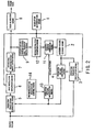
- PIG. 7 is a block diagram showing the structure of the fourth embodiment not belonging to the present invention. Since the fourth embodiment employs some elements common to the first embodiment, the following description will not repeat the explanation for such elements, while affixing like reference numerals to like elements.
- an entropy decoder 47 reproduces data such as quantized coefficients, picture resolution, quantizer step size, coding scheme, and motion vectors, out of the coded frame data received from a sending end.
- the entropy decoder 47 distributes those reproduced data to other functional blocks in the apparatus. More specifically, the quantized coefficients and quantizer step size are sent to the dequantizer 29a; the picture resolution is delivered to the upsampling switch 30b and lowpass filter switch 32b; the coding scheme is supplied to the prediction picture switch 24b and upsampling unit 30a; the motion vectors are provided to the prediction picture generator 24a and lowpass filter switch 32b. Operations of those functional blocks within the area indicated by the alternating long and short dashes will not be described here, because they work in the same way as described in the first embodiment.
- the output of this video decoding apparatus will branch off from the decoded picture generation unit 31. That is, the decoded pictures fully reconstructed by the decoded picture generation unit 31 are outputted to an external video monitor or like devices, while being saved in the frame memory 22 as the reference frames for predictive coding.
- the video decoding apparatus of the fourth embodiment receives and decodes the coded video signal produced by a video coding apparatus.
- This decoding process employs the upsampling unit 30a.
- the upsampling unit 30a allows the pictures to be reproduced without noises or artifacts, even if some different coding schemes are used for compressing a frame, or in other words, even if the pixel values exhibit a big difference at a certain block boundary.
- This fifth embodiment is related to a video coding apparatus.
- FIG. 2 shows the concept of the fifth embodiment. Because of its similarity to the first embodiment depicted in FIG. 1, like reference numerals are affixed to like elements in FIG. 2.
- the fifth embodiment is distinguishable from the first embodiment in that a second resolution conversion means 12 functions differently from the second resolution means recited in the first embodiment, and also in that the video coding apparatus further comprises prediction picture modification means 13 disposed between the prediction picture generation means 4 and decoded picture generation means 11. Further, the fifth embodiment comprises prediction picture modification control means 14 which is linked to the prediction picture modification means 13.
- the prediction error signal reproduced by the dequantization/inverse orthogonal transformation means 9 will have the same reduced picture resolution.
- the second resolution conversion means 12 attempts to restore the original resolution by performing an upsampling process.
- this upsampling process may refer to the pixels belonging to the blocks beyond a block boundary regardless of the magnitude of those pixel values, as in the conventional upsampling algorithms.
- the prediction picture modification control means 14 determines whether or not to modify the values of pixels located near a particular block boundary. In the case that the first resolution conversion means 6 downsampled the original prediction error signal to reduce the picture resolution, and if the prediction picture modification control means 14 has determined to modify the pixel values at the particular block boundary, the prediction picture modification means 13 will modify the values of the pixels located along the particular block boundary, with reference to other pixels beyond that boundary.
- the prediction picture modification control means 14 examines the prediction picture produced by the prediction picture generation means 4 to evaluate the block-to-block difference in terms of pixel values. If a any critical difference exceeding a certain threshold level is observed in any particular blocks, the prediction picture modification control means 14 regards the boundary between such blocks as the aforementioned particular block boundary.
- this particular block boundary is referred to as a critical block boundary where modification of pixel values is required.
- the critical block boundary may not be directly identified by bitwise comparison of pixels, but is estimated through observation of blocks based on either of the following two criteria.
- the first criterion is the difference in coding schemes being applied to adjacent blocks.
- the prediction picture modification control means 14 examines the coding schemes actually assigned by the prediction parameter calculation means 3 for each block. If a block of interest is adjacent to any other blocks that are subject to a different coding scheme, the prediction picture modification control means 14 recognizes the boundary of the two adjacent blocks as a critical boundary.
- the second criterion is the difference in motion vectors.
- the motion vectors produced by the prediction parameter calculation means 3 are evaluated on a block-by-block basis. More specifically, the prediction picture modification control means 14 compares the motion vector of a block of interest with that of any adjacent block. If the observed difference in vector magnitude is larger than a predetermined threshold, the prediction picture modification control means 14 recognizes that block boundary as a critical boundary.
- any block-to-block difference in coding schemes applied implies the presence of some critical differences in pixel values.
- discontinuous variations observed in the motion vector domain will provide the same implication.
- the prediction picture modification control means 14 detects such critical differences and determines to modify the pixel values along the critical block boundary. Then the prediction picture modification control means 14 commands the prediction picture modification means 13 to make a smoothing operation to eliminate the discontinuity in the pixel values.
- FIG. 11 shows some specific profiles of pixel values at some points in a video coding apparatus according to the present invention.
- a source picture (a) contains both kinds of blocks, one subject to intraframe coding and the other subject to interframe coding.
- the boundary of those different kinds of blocks is indicated by a vertical dashed line. Since the intraframe-coding block on the left side have no reference frame for frame prediction, their pixel values in the prediction picture (b) will simply be set to zeros. Accordingly, the resultant prediction error signal (c) will exhibit large values in the intraframe-coding block, while showing small values for the interframe-coding block.
- the upsampling process executed by the second resolution conversion means 12 will cause a mixture of differently coded pixel values in the vicinity of the block boundary, introducing some distortion in the reproduced prediction error signal (d), as is the case of the conventional upsampling process noted earlier.
- the prediction picture modification means 13 applies a smoothing operation to the pixels located along the critical block boundary in the prediction picture (b), thereby yielding a smoothed prediction picture (e).
- the decoded picture generation means 11 finally renders the decoded picture (f) which is quite similar to the original source picture (a). That is, the video coding apparatus of the fifth embodiment prevents any noises from being introduced in the vicinity of block boundaries in the decoded picture, unlike the conventional video coding apparatus which suffer from this kind of noises.
- the prediction picture modification means 13 forwards the prediction picture as is to the decoded picture generation means 11.
- the fifth embodiment allows the pictures to be reproduced without undesired noises, even if some pixel values exhibit some discontinuity at a certain block boundary.
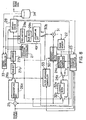
- FIG. 8 is a block diagram showing a detailed structure of the fifth embodiment of the present invention. Since the fifth embodiment has basically the same structure as that of the first embodiment depicted in FIG. 3, the following description will focus on its distinctive points, while affixing like reference numerals to like elements.
- This fifth embodiment is distinguishable from the first embodiment in that an upsampling unit 49 works differently from the upsampling unit 30a of the first embodiment, and also in that a boundary neighborhood filter 50 is newly inserted between the lowpass filter switch 32b and decoded picture generation unit 31 of the first embodiment. Further, the fifth embodiment is distinguishable in that it comprises a filter operation controller 53 coupled to the boundary neighborhood filter 50. Unlike the upsampling unit 30a in the first embodiment, the upsampling unit 49 does not examine whether or not each block is adjacent to any other blocks being subject to a different coding scheme. Rather, it executes the conventional upsampling process as illustrated in FIG. 16, referring to any relevant pixels not only within the block but also beyond the block boundary.
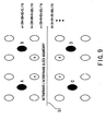
- FIG. 9 shows an upsampling process performed by the upsampling unit 49.
- black dots and upper-case alphabetical letters represent QCIF pixels and their respective prediction error signal values
- white dots and lower-case letters represent CIF pixels and their respective prediction error signal values.
- a dashed line 51 indicates a block boundary where the coding scheme is changed from inter-frame coding to intra-frame coding or vise versa.
- the upsampling unit 49 refers not only to the QCIF pixels A and B but also to the pixels C and D that are subject to the different coding scheme.
- the filter operation controller 53 receives the picture resolution from the resolution selection controller 21 and the coding scheme for each block from the prediction parameter calculator 23.
- the filter operation controller 53 examines whether or not the block of interest is adjacent to any other blocks being subject to a different coding scheme. If such a neighboring block is found, the filter operation controller 53 will send an operation command signal to activate the boundary neighborhood filter 50.
- the boundary neighborhood filter 50 is kept informed of the coding scheme for each frame determined by the prediction parameter calculator 23. Upon receipt of the operation command signal from the filter operation controller 53, the boundary neighborhood filter 50 executes a smoothing operation to eliminate the discontinuity in the pixel values near the block boundary. This smoothed prediction error signal is then supplied to the decoded picture generation unit 31.
- FIG. 10 explains a process executed by the boundary neighborhood filter 50. It is assumed that a prediction picture involving two different coding schemes is supplied to the boundary neighborhood filter 50 via the lowpass filter switch 32b. White dots in FIG. 10 represent some pixels as part of the prediction picture, and lower-case letters affixed to them indicate their respective pixel values.
- a block boundary 52 is a boundary at which the coding scheme is switched from inter-frame coding to intra-frame coding or vise versa. More specifically, the lower-right block below the block boundary 52 are intraframe-coded, while the other blocks are interframe-coded.
- the boundary neighborhood filter 50 applies a smoothing operator to the pixels adjacent to the block boundary 52 so that their values h, i, j, k, l, n, o, p , q, r, t , and u will be continuous. More specifically, the boundary neighborhood filter 50 calculates a new pixel value for each pixel belonging to the interframe-coded block. Take the pixel value j for example.
- j ⁇ ( 9 c + 9 d + 9 i + 9 j + 3 e + 3 f + 3 k + 3 l ) / 64 .
- the prediction picture When the pixels in the interframe-coded block have large values, the prediction picture will exhibit a large variation or discontinuity in its pixel value profiles, because of zeros are assigned to the intraframe-coded block.
- the boundary neighborhood filter 50 smoothes such variation and eliminates the discontinuity of pixel values, as further described below with reference to FIG. 11.
- FIG. 11 is a diagram to explain a process of predictive coding and decoding of a source picture.
- FIG. 11 consists of six graphs (a) to (f), which represent the various profiles of pixel values in the neighborhood of a certain block boundary, arranged along the time axis of a coding process.
- a source picture (a) contains the following two kinds of blocks: one block subject to intraframe coding (on the left) and another block subject to interframe coding (on the right).
- the boundary of those different kinds of blocks is indicated by as a vertical dashed line.
- their pixel values in a prediction picture (b) are zeros. Therefore, the resultant prediction error signal (a)-(b), or (c), exhibits large values in the intraframe-coded block and small values in the interframe-coded block.
- the boundary neighborhood filter 50 applies a smoothing operation to the pixels along the block boundary in the original prediction picture (b), and accordingly, a smoothed prediction picture (e) can be obtained.
- the decoded picture generation means 11 thus renders a fully decoded picture (f) by adding the reproduced prediction error signal (d) to the smoothed prediction picture (e). That is, the video coding apparatus of the fifth embodiment prevents the noises to be introduced in the neighborhood of block boundary in the decoded picture (f), unlike the conventional video coding apparatus which suffer from this kind of noises.
- the above-described fifth embodiment is configured so that the filter operation controller 53 will receive the coding scheme of each block from the prediction parameter calculator 23 in addition to the picture resolution from the resolution selection controller 21.
- it can be configured so that it will receive the motion vectors, instead of the coding scheme, from the same prediction parameter calculator 23.
- the filter operation controller 53 compares the motion vector of a block of interest with those of any adjacent blocks in terms of magnitude of vectors, after detecting that the prediction error signal has been downsampled to the QCIF resolution. If any difference larger than a predetermined threshold is observed, the filter operation controller 53 will send an operation command signal to the boundary neighborhood filter 50.
- the boundary neighborhood filter 50 Upon receipt of the operation command signal from the filter operation controller 53, the boundary neighborhood filter 50 executes a smoothing operation to eliminate the discontinuity in the pixel values along the block boundary.
- the smoothing algorithm used here can not be the same as that described earlier. This is because the above block boundary does not always means a boundary of different coding schemes. That is, since the blocks on one side of the boundary are not always intraframe-coded, the pixels in those blocks may have non-zero values.
- a proposed smoothing algorithm will now be described below with reference to FIG. 12.
- FIG. 12 is a diagram to explain a smoothing process performed by the boundary neighborhood filter 50 when an operation command signal is sent thereto. It is assumed that the lowpass filter switch 32b supplied the boundary neighborhood filter 50 with a prediction picture involving some adjacent motion vectors exhibiting a large difference in magnitude which exceeds a predetermined threshold. More specifically, white dots in FIG. 12 represent pixels as part of the prediction picture and lower-case letters affixed to them indicate their respective pixel values. The motion vectors on one side of a block boundary 55 are not equal to those on the other side in terms of vector magnitudes but, rather, the difference is larger than a predetermined threshold.
- the boundary neighborhood filter 50 will first calculate average pixel values A, B, C , and D .
- those average values are corresponding to the values of imaginary pixels located between a first series of pixels [ h, i, j , k , l, n , t ] immediately adjacent to the block boundary 55 and a second series of pixels [ a, b, c, d, e, f, g, m, s ] aligned next to the first series of pixels.
- the boundary neighborhood filter 50 further calculates average pixel values E and F , which correspond to the values of black-dot imaginary pixels between a third series of pixels [ o, p, q, r, u ] immediately adjacent to the block boundary 55 and a fourth series of pixels [ v , w , x ] aligned next to the third series of pixels.
- the boundary neighborhood filter 50 smoothes down the variation in pixel values, when it was steep in the neighborhood of a block boundary.
- the fifth embodiment may allow the following modified arrangement. That is, the filter operation controller 53 is eliminated and, instead, the boundary neighborhood filter 50 is informed of the picture resolution directly from the resolution selection controller 21.
- the boundary neighborhood filter 50 will always apply the above-described smoothing operation to the pixels in the neighborhood of every block boundary, regardless of whether any critical difference in pixel values is present or not.
- This sixth embodiment is related to a video decoding apparatus.
- FIG. 13 shows a specific structure of the sixth embodiment. Since the sixth embodiment employs some elements common to the fifth embodiment, the following description will not repeat the explanation for such elements while affixing like reference numerals to like elements.
- an entropy decoder 54 reproduces quantized coefficients, picture resolution, quantizer step size, coding scheme, and motion vectors as originally produced, by processing the coded frame data received from a sending end.
- the entropy decoder 54 distributes those reproduced signals to other functional blocks in the apparatus. More specifically, the quantized coefficients and quantizer step size are sent to the dequantizer 29a; the picture resolution is delivered to the upsampling switch 30b, lowpass filter switch 32b, and filter operation controller 53; the coding scheme is supplied to the prediction picture switch 24b, boundary neighborhood filter 50, and filter operation controller 53; the motion vectors are provided to the prediction picture generator 24a and lowpass filter switch 32b.
- the prediction error signal reproduced by the entropy decoder 54 may have originally been converted down to the QCIF resolution at the sending end. Also, the reproduced prediction picture may contain some adjacent blocks that exhibit critical differences in pixel values. Upon detection of those events and conditions, the filter operation controller 53 issues an operation command signal to the boundary neighborhood filter 50. Such critical differences in pixel values are implied by any block-to-block difference in coding schemes applied or, alternatively, by considerable discontinuous variations observed in the motion vector domain. Upon receipt of the operation command signal from the filter operation controller 53, the boundary neighborhood filter 50 executes a smoothing operation to eliminate the discontinuity in the pixel values near the block boundary concerned.
- the output of this video decoding apparatus is obtained at the decoded picture generation unit 31.
- the video frame signals fully reconstructed by the decoded picture generation unit 31 are outputted to a video monitor or other like devices, while being saved in the frame memory 22 as the reference frames for predictive coding.
- the video decoding apparatus of the sixth embodiment receives and decodes the coded video signal produced by a video coding apparatus.
- the decoding process involves functions of the boundary neighborhood filter 50 and the filter operation controller 53, which were introduced in the fifth embodiment of the present invention. Those two elements allow the pictures to be reproduced without introducing noises, even if the pixel values exhibit some discontinuity at a certain block boundary.
- the second resolution conversion means performs an upsampling process to restore the original resolution.
- the second resolution conversion means calculates the value of each pixel in a particular block, without referring to pixels belonging to any adjacent block that is subject to another coding scheme.
- the upsampling process will totally neglect the pixels in other blocks but only refer to the present block.
- the present invention prevents the difference in coding schemes from affecting the reproduced prediction error signal, as opposed to the conventional upsampling process which causes some unwanted noises in the reproduced signal.
- the reproduced prediction error signal will exhibit a near-original signal profile. Therefore, the present invention can reproduce the original pictures without introducing unwanted noises, even if some mixed coding schemes are used for compressing a frame, or in other words, even if the pixel values exhibit a critical difference at a certain block boundary.
- the low-pass filter is selectively activated only when a low-resolution coding is conducted and the prediction picture contains some fast-motion blocks.
- This structural arrangement will prevent the sharpness of images in less-active blocks (background images, for example) as part a picture from being spoiled.
- the present invention applies a smoothing operation to the neighborhood of a critical block boundary where the pixel values exhibit a considerable variation, or a large discontinuity, due to the mixed use of different coding schemes at some adjacent blocks or intensive differences in the magnitude of motion vectors at a block boundary.
- the smoothing operation allows pictures to be reproduced without noises, even if the pixel values in a frame exhibit some discontinuity at a certain block boundary.
Claims (10)
- Videokodierungsvorrichtung zum Durchführen einer vorhersagenden Kodierung von digitalen Videoeingangssignalen, umfassend:(a) Auflösungsbestimmungsmittel zum Auswählen einer Bildauflösung zum Kodieren eines gegebenen Videoeingangssignals;(b) Kodierungsmittel zum Erzeugen eines kodierten Videosignals durch Durchführen einer vorhersagenden Kodierung des Videoeingangssignals auf einer Basis von Block zu Block gemäß der Bildauflösung, die durch das Auflösungsbestimmungsmittel ausgewählt ist; und(c) Dekodierungsmittel zum Dekodieren des kodierten Videosignals, um ein dekodiertes Bild zur Verwendung in der vorhersagenden Kodierung zu erzeugen, während jeder Block geringer Auflösung zurück zu einer hohen Auflösung mit Bezug auf Vorhersagefehlersignale nur von Pixeln innerhalb des jeden Blocks geringer Auflösung konvertiert wird.
- Videokodierungsvorrichtung nach Anspruch 1, wobei:das Kodierungsmittel umfasst:(b1) Speichermittel eines dekodierten Bildes zum Speichern eines vergangenen dekodierten Bildes, reproduziert durch das Dekodierungsmittel in einem vorherigen Rahmen;(b2) Vorhersageparameter-Kalkulationsmittel, das mit dem Auflösungsbestimmungsmittel gekoppelt ist, zum Bestimmen, welches von zwei Kodierungsschemata verwendet werden sollte, um einzelne Blöcke zu kodieren, durch Vergleichen eines Quellenbildes eines aktuellen Rahmens mit dem vergangenen dekodierten Bild, das in dem Speichermittel des dekodierten Bildes gespeichert ist, und auch zum Kalkulieren von Bewegungsvektoren der Blöcke in dem Quellenbild, wobei:die zwei Kodierungsschemata eine Intrarahmenkodierung und eine Interrahmenkodierung enthalten, unddie Blöcke durch Partitionieren eines gegebenen Bildes in Stücke gemäß der Bildauflösung definiert sind, die durch das Auflösungsbestimmungsmittel bestimmt ist;(b3) Vorhersagebild-Generierungsmittel zum Erzeugen eines Vorhersagebildes durch Kalkulation von Pixelwerten auf einer Basis von Block zu Block, wobei die Kalkulation der Pixelwerte enthält:Zuweisung von Nullen zu Pixelwerten der Blöcke, die Gegenstand der Intrarahmenkodierung sind, undKalkulation der Pixelwerte der anderen Blöcke, die Gegenstand der Interrahmenkodierung sind, basierend auf dem vergangenen dekodierten Bild, das in dem Speichermittel des dekodierten Bildes gespeichert ist, und der Bewegungsvektoren, die durch das Vorhersageparameter-Kalkulationsmittel erhalten werden;(b4) Vorhersagefehlersignal-Generierungsmittel zum Erzeugen eines Vorhersagefehlersignals für jeden Block durch Kalkulieren von Differenzen zwischen dem Quellenbild und dem Vorhersagebild;(b5) ein erstes Auflösungskonvertierungsmittel zum Abwärtsabtasten des Vorhersagefehlersignals, das durch das Vorhersagefehlersignal-Generierungsmittel erzeugt wird, um die niedrige Auflösung vorzusehen, abhängig von der Bildauflösung, die durch das Auflösungsbestimmungsmittel bestimmt ist;(b6) Orthogonaltransformations-/Quantisierungsmittel zum Anwenden eines orthogonalen Transformationsprozesses und eines Quantisierungsprozesses auf das Vorhersagefehlersignal, das durch das erste Auflösungskonvertierungsmittel verarbeitet wird; und(b7) Codezuordnungsmittel zum Ausgeben eines Codewortes, das für eine gegebene Menge von Daten relevant ist, wobei das Codewort aus einer vordefinierten Codeworttabelle abgerufen wird, wobei:die gegebene Menge von Daten mindestens die Ausgabe des Orthogonal trans formations-/Quantisierungsmittels, die Bildauflösung, die durch das Auflösungsbestimmungsmittel bestimmt ist, das Kodierungsschema, das durch das Vorhersageparameter-Kalkulationsmittel bestimmt ist, und die Bewegungsvektoren, die durch das Vorhersageparameter-Kalkulationsmittel kalkuliert sind, enthält, unddie vorbestimmte Codeworttabelle eine Vielzahl von Codeworten enthält, die zuvor jeder möglichen Kombination der gegebenen Menge von Daten zugewiesen sind; unddas Dekodierungsmittel umfasst:(c1) Dequantisierungs-/Umkehrorthogonaltransformationsmittel zum Anwenden eines Dequantisierungsprozesses und eines Umkehrorthogonaltransformationsprozesses auf die Ausgabe des Orthogonaltransformations-/Quantisierungsmittels, um das Vorhersagefehlersignal zu reproduzieren;(c2) ein zweites Auflösungskonvertierungsmittel zum Anwenden eines Aufwärtsabtastprozesses auf das reproduzierte Vorhersagefehlersignal, das von dem Dequantisierungs-/Umkehrorthogonaltransformationsmittel gesendet wird, um die hohe Auflösung wiederzuerlangen, falls das reproduzierte Vorhersagefehlersignal abwärts zu der geringen Auflösung durch das erste Auflösungskonvertierungsmittel konvertiert wurde, wobei der Aufwärtsabtastprozess den Wert von jedem Pixel in jedem Block mit Bezug auf Pixel in dem Block kalkuliert, aber ohne Bezug auf Pixel in anderen Blöcken; und(c3) Generierungsmittel eines dekodierten Bildes zum Aufbauen eines dekodierten Bildes durch Hinzufügen des reproduzierten Vorhersagefehlersignals, das durch das zweite Auflösungskonvertierungsmittel verarbeitet wird, zu dem Vorhersagebild, das durch das Vorhersagebild-Generierungsmittel erzeugt wird, und zum Ausgeben des dekodierten Bildes zu dem Speichermittel des dekodierten Bildes.
- Videokodierungsvorrichtung nach Anspruch 2, wobei:das zweite Auflösungskonvertierungsmittel untersucht, welches Kodierungsschema beim Kodieren von jedem Block benachbart zu dem Block von Interesse verwendet wurde, basierend auf den Kodierungsschemata der einzelnen Blöcke, die durch das Vorhersageparameter-Kalkulationsmittel bestimmt sind;falls das Kodierungsschema eines benachbarten Blocks das gleiche wie das des Blocks von Interesse ist, das zweite Auflösungskonvertierungsmittel den Aufwärtsabtastprozess für das reproduzierte Vorhersagefehlersignal ausführt, um die hohe Auflösung zu erlangen, unter Bezug auf Werte des reproduzierten Vorhersagefehlersignals von Pixeln, die zu dem benachbarten Blocks gehören, ebenso wie von Pixeln, die zu dem Block von Interesse gehören; undfalls sich das Kodierungsschema eines benachbarten Blocks von dem des Blocks von Interesse unterscheidet, das zweite Auflösungskonvertierungsmittel den Aufwärtsabtastprozess für das reproduzierte Vorhersagefehlersignal ausführt, um die hohe Auflösung zu erlangen, unter Bezug auf das reproduzierte Vorhersagefehlersignal von Pixeln, die nicht zu dem benachbarten Block gehören, der mit dem anderen Kodierungsschema kodiert ist.
- Videokodierungsvorrichtung nach Anspruch 2, wobei das zweite Auflösungskonvertierungsmittel den Aufwärtsabtastprozess für das reproduzierte Vorhersagefehlersignal ausführt, um die hohe Auflösung zu erlangen, nur unter Bezug auf das reproduzierte Vorhersagefehlersignal von Pixeln, die zu dem Block von Interesse gehören.
- Videokodierungsvorrichtung nach Anspruch 2, ferner umfassend Hochfrequenz-Unterdrückungsmittel, das zwischen dem Vorhersagebild-Generierungsmittel und dem Vorhersagefehlersignal-Generierungsmittel aufgestellt ist, zum Unterdrücken eines vorbestimmten Bereichs von Hochfrequenzkomponenten, die in dem Vorhersagebild enthalten sind, das durch das Vorhersagebild-Generierungsmittel erzeugt wird.
- Videokodierungsvorrichtung nach Anspruch 5, wobei das Hochfrequenz-Unterdrückungsmittel auf die Bewegungsvektoren verweist, die, einer für jeden Block, durch das Vorhersageparameter-Kalkulationsmittel kalkuliert sind, um die Blöcke in eine erste Gruppe von Blöcken, die eine schnelle Bewegung aufweisen, und eine zweite Gruppe von Blöcken, die eine weniger aktive Bewegung aufweisen, zu klassifizieren, und die Hochfrequenzkomponenten nur unterdrückt, wenn der Block von Interesse in die erste Gruppe von Blöcken fällt und das Auflösungsbestimmungsmittel die geringe Auflösung bestimmt hat.
- Videokodierungsvorrichtung nach Anspruch 1, wobei:das Kodierungsmittel umfasst:(b1) Speichermittel eines dekodierten Bildes zum Speichern eines vergangenen dekodierten Bildes, das durch das Dekodierungsmittel in einem vorherigen Rahmen reproduziert ist;(b2) Vorhersageparameter-Kalkulationsmittel, das mit dem Auflösungsbestimmungsmittel gekoppelt ist, zum Bestimmen, welches von zwei Kodierungsschemata verwendet werden sollte, um einzelne Blöcke zu kodieren, durch Vergleichen des Quellenbildes des aktuellen Rahmens mit dem vergangenen dekodierten Bild, das in dem Speichermittel des dekodierten Bildes gespeichert ist, und auch zum Kalkulieren von Bewegungsvektoren der Blöcke in dem Quellenbild, wobei:die zwei Kodierungsschemata eine Intrarahmenkodierung und eine Interrahmenkodierung enthalten, unddie Blöcke durch Partitionieren eines gegebenen Bildes in Stücke gemäß der Bildauflösung definiert sind, die durch das Auflösungsbestimmungsmittel bestimmt ist;(b3) Vorhersagebild-Generierungsmittel zum Erzeugen eines Vorhersagebildes durch Kalkulation von Pixelwerten auf einer Basis von Block zu Block, wobei die Kalkulation der Pixelwerte enthält:Zuweisung von Nullen zu Pixelwerten der Blöcke, die Gegenstand der Intrarahmenkodierung sind, undKalkulation der Pixelwerte der anderen Blöcke, die Gegenstand der Interrahmenkodierung sind basierend auf dem vergangenen dekodierten Bild, das in dem Speichermittel des dekodierten Bildes gespeichert ist, und der Bewegungsvektoren, die durch das Vorhersageparameter-Kalkulationsmittel erhalten werden:(b4) Vorhersagefehlersignal-Generierungsmittel zum Erzeugen eines Vorhersagefehlersignals für jeden Block durch Kalkulieren von Differenzen zwischen dem Quellenbild und dem Vorhersagebild;(b5) Orthogonaltransformationsmittel zum Erhalten von Transformationskoeffizienten durch Anwenden einer orthogonalen Transformation auf das Vorhersagefehlersignal, das durch das Vorhersagefehlersignal-Generierungsmittel erzeugt wird, gemäß der Bildauflösung, die durch das Auflösungsbestimmungsmittel bestimmt ist, und zum Extrahieren von Niederfrequenzkomponenten der erhaltenen Transformationskoeffizienten;(b6) Quantisierungsmittel zum Anwenden eines Quantisierungsprozesses auf die Ausgabe des Orthogonaltransformationsmittels; und(b7) Codezuordnungsmittel zum Ausgeben eines Codewortes, das für eine gegebene Menge von Daten relevant ist, wobei das Codewort aus einer vordefinierten Codeworttabelle abgerufen wird, wobei:die gegebene Menge von Daten mindestens die Ausgabe des Quantisierungsmittels, die Bildauflösung, die durch das Auflösungsbestimmungsmittel bestimmt ist, das Kodierungsschema, das durch das Vorhersageparameter-Kalkulationsmittel bestimmt ist, und die Bewegungsvektoren, die durch das Vorhersageparameter-Kalkulationsmittel kalkuliert sind, enthält, unddie vorbestimmte Codeworttabelle eine Vielzahl von Codeworten enthält, die zuvor jeder möglichen Kombination der gegebenen Menge von Daten zugewiesen sind; unddas Dekodierungsmittel umfasst:(c1) Dequantisierungs-/Umkehrorthogonaltransformationsmittel zum Anwenden eines Dequantisierungsprozesses und eines Umkehrorthogonaltransformationsprozesses auf die Ausgabe des Quantisierungsmittels, um das Vorhersagefehlersignal zu reproduzieren;(c2) Hochauflösungskonvertierungsmittel zum Anwenden eines Aufwärtsabtastprozesses auf das reproduzierte Vorhersagefehlersignal, das von dem Dequantisierungs-/Umkehrorthogonaltransformationsmittel gesendet wird, um die hohe Auflösung wiederzuerlangen, falls sich das reproduzierte Vorhersagefehlersignal aus den Niederfrequenzkomponenten der Transformationskoeffizienten ableitet, die durch das Orthogonaltransformationsmittel extrahiert werden, wobei der Aufwärtsabtastprozess den Wert von jedem Pixel in jedem Block mit Bezug auf Pixel in dem vorliegenden Block kalkuliert, aber ohne Bezug auf Pixel in anderen Blöcken; und(c3) Generierungsmittel eines dekodierten Bildes zum Aufbauen eines dekodierten Bildes durch Hinzufügen des reproduzierten Vorhersagefehlersignals, das durch das Hochauflösungskonvertierungsmittel verarbeitet wird, zu dem Vorhersagebild, das durch das Vorhersagebild-Generierungsmittel erzeugt wird, und zum Ausgeben des dekodierten Bildes zu dem Speichermittel des dekodierten Bildes.
- Videokodierungsvorrichtung nach Anspruch 7, ferner umfassend ein Hochfrequenz-Unterdrückungsmittel, das zwischen dem Vorhersagebild-Generierungsmittel und dem Vorhersagefehlersignal-Generierungsmittel aufgestellt ist, zum Unterdrücken eines vorbestimmten Bereichs von Hochfrequenzkomponenten, die in dem Vorhersagebild enthalten sind, das durch das Vorhersagebild-Generierungsmittel erzeugt wird.
- Videokodierungsvorrichtung nach Anspruch 8, wobei das Hochfrequenz-Unterdrückungsmittel auf die Bewegungsvektoren verweist, die, einer für jeden Block, durch das Vorhersageparameter-Kalkulationsmittel kalkuliert sind, um die Blöcke in eine erste Gruppe von Blöcken, die eine schnelle Bewegung aufweisen, und eine zweite Gruppe von Blöcken, die weniger aktive Bewegung aufweisen, zu klassifizieren, und die Hochfrequenzkomponenten nur unterdrückt, wenn der Block von Interesse in die erste Gruppe von Blöcken fällt und das Auflösungsbestimmungsmittel die geringe Auflösung als die Bildauflösung bestimmt hat.
- Ein Videokodierungsverfahren, um vorhersagende Kodierung eines digitalen Videoeingangssignals durchzuführen, die Schritte umfassend:(a) Bestimmen einer Bildauflösung, die in einer Videokodierung eines Quellenbildes zu verwenden ist;(b) Partitionieren eines Rahmens des digitalen Videoeingangssignals in eine Vielzahl von Blöcken;(c) Konvertieren einer Auflösung von jedem Block, der in dem Partitionierungsschritt (b) erhalten wird, von einer hohen Auflösung zu einer geringen Auflösung, gemäß der Bildauflösung, die durch das Auflösungsbestimmungsmittel bestimmt wird; und(d) vorhersagendes Kodieren von Blöcken geringer Auflösung, die in dem Konvertierungsschritt (c) konvertiert werden, während eines aus einer Vielzahl von Kodierungsschemata auf einer Basis von Block zu Block angewendet wird, wobei jeder Block geringer Auflösung, der in dem Konvertierungsschritt (c) konvertiert wird, zu der hohen Auflösung beim Erzeugen eines dekodierten Bildes zurück konvertiert wird, mit Bezug auf Vorhersagefehlersignale nur von Pixeln innerhalb von jedem Block geringer Auflösung.
Priority Applications (6)
| Application Number | Priority Date | Filing Date | Title |
|---|---|---|---|
| EP20050025043 EP1646245B1 (de) | 1996-10-24 | 1997-07-08 | Videokodierungs- und Videodekodierungsvorrichtung |
| EP20050025045 EP1648176B1 (de) | 1996-10-24 | 1997-07-08 | Videokodierungs- und Videodekodierungsvorrichtung |
| EP20060012867 EP1699245B1 (de) | 1996-10-24 | 1997-07-08 | Videokodierungsvorrichtung |
| EP20060017968 EP1725048B1 (de) | 1996-10-24 | 1997-07-08 | Videokodierungs- und Videodekodierungsvorrichtung |
| EP20080000089 EP1901562B1 (de) | 1996-10-24 | 1997-07-08 | Vorrichtung zur Videodekodierung |
| EP04012419A EP1455536B1 (de) | 1996-10-24 | 1997-07-08 | Videokodierungs- und Videodekodierungsvorrichtung |
Applications Claiming Priority (4)
| Application Number | Priority Date | Filing Date | Title |
|---|---|---|---|
| JP281984/96 | 1996-10-24 | ||
| JP28198496 | 1996-10-24 | ||
| JP29475396A JP3466032B2 (ja) | 1996-10-24 | 1996-11-07 | 動画像符号化装置および復号化装置 |
| JP294753/96 | 1996-11-07 |
Related Child Applications (3)
| Application Number | Title | Priority Date | Filing Date |
|---|---|---|---|
| EP20050025043 Division EP1646245B1 (de) | 1996-10-24 | 1997-07-08 | Videokodierungs- und Videodekodierungsvorrichtung |
| EP20050025045 Division EP1648176B1 (de) | 1996-10-24 | 1997-07-08 | Videokodierungs- und Videodekodierungsvorrichtung |
| EP04012419A Division EP1455536B1 (de) | 1996-10-24 | 1997-07-08 | Videokodierungs- und Videodekodierungsvorrichtung |
Publications (3)
| Publication Number | Publication Date |
|---|---|
| EP0838955A2 EP0838955A2 (de) | 1998-04-29 |
| EP0838955A3 EP0838955A3 (de) | 1999-03-03 |
| EP0838955B1 true EP0838955B1 (de) | 2006-04-26 |
Family
ID=26554410
Family Applications (7)
| Application Number | Title | Priority Date | Filing Date |
|---|---|---|---|
| EP19970111543 Expired - Lifetime EP0838955B1 (de) | 1996-10-24 | 1997-07-08 | Videokodierungs- und Videodekodierungsvorrichtung |
| EP20080000089 Expired - Lifetime EP1901562B1 (de) | 1996-10-24 | 1997-07-08 | Vorrichtung zur Videodekodierung |
| EP04012419A Expired - Lifetime EP1455536B1 (de) | 1996-10-24 | 1997-07-08 | Videokodierungs- und Videodekodierungsvorrichtung |
| EP20060017968 Expired - Lifetime EP1725048B1 (de) | 1996-10-24 | 1997-07-08 | Videokodierungs- und Videodekodierungsvorrichtung |
| EP20060012867 Expired - Lifetime EP1699245B1 (de) | 1996-10-24 | 1997-07-08 | Videokodierungsvorrichtung |
| EP20050025045 Expired - Lifetime EP1648176B1 (de) | 1996-10-24 | 1997-07-08 | Videokodierungs- und Videodekodierungsvorrichtung |
| EP20050025043 Expired - Lifetime EP1646245B1 (de) | 1996-10-24 | 1997-07-08 | Videokodierungs- und Videodekodierungsvorrichtung |
Family Applications After (6)
| Application Number | Title | Priority Date | Filing Date |
|---|---|---|---|
| EP20080000089 Expired - Lifetime EP1901562B1 (de) | 1996-10-24 | 1997-07-08 | Vorrichtung zur Videodekodierung |
| EP04012419A Expired - Lifetime EP1455536B1 (de) | 1996-10-24 | 1997-07-08 | Videokodierungs- und Videodekodierungsvorrichtung |
| EP20060017968 Expired - Lifetime EP1725048B1 (de) | 1996-10-24 | 1997-07-08 | Videokodierungs- und Videodekodierungsvorrichtung |
| EP20060012867 Expired - Lifetime EP1699245B1 (de) | 1996-10-24 | 1997-07-08 | Videokodierungsvorrichtung |
| EP20050025045 Expired - Lifetime EP1648176B1 (de) | 1996-10-24 | 1997-07-08 | Videokodierungs- und Videodekodierungsvorrichtung |
| EP20050025043 Expired - Lifetime EP1646245B1 (de) | 1996-10-24 | 1997-07-08 | Videokodierungs- und Videodekodierungsvorrichtung |
Country Status (4)
| Country | Link |
|---|---|
| US (2) | US6104434A (de) |
| EP (7) | EP0838955B1 (de) |
| JP (1) | JP3466032B2 (de) |
| DE (7) | DE69738262T2 (de) |
Families Citing this family (111)
| Publication number | Priority date | Publication date | Assignee | Title |
|---|---|---|---|---|
| JP3466032B2 (ja) * | 1996-10-24 | 2003-11-10 | 富士通株式会社 | 動画像符号化装置および復号化装置 |
| US20020196853A1 (en) * | 1997-06-04 | 2002-12-26 | Jie Liang | Reduced resolution video decompression |
| WO1999004573A1 (en) * | 1997-07-16 | 1999-01-28 | Koninklijke Philips Electronics N.V. | Video coding method and device, and corresponding decoding device |
| US7239755B1 (en) | 1997-07-30 | 2007-07-03 | Lg Electronics Inc. | Method of reducing a blocking artifact when coding moving picture |
| KR100244290B1 (ko) * | 1997-09-09 | 2000-02-01 | 구자홍 | 저속 전송에서의 동영상을 위한 디블록킹 필터링 방법 |
| US6823016B1 (en) * | 1998-02-20 | 2004-11-23 | Intel Corporation | Method and system for data management in a video decoder |
| JP4264571B2 (ja) * | 1998-04-09 | 2009-05-20 | ソニー株式会社 | ディジタル画像復号装置及び方法、並びに記録媒体 |
| US6249549B1 (en) * | 1998-10-09 | 2001-06-19 | Matsushita Electric Industrial Co., Ltd. | Down conversion system using a pre-decimation filter |
| JP3576402B2 (ja) * | 1998-10-23 | 2004-10-13 | 三菱電機株式会社 | 画像復号化装置 |
| KR100313217B1 (ko) * | 1998-12-23 | 2001-12-28 | 서평원 | 파이프라인dct장치 |
| US6552749B1 (en) * | 1999-01-29 | 2003-04-22 | Intel Corporation | Method and apparatus for video motion compensation, reduction and color formatting |
| US6307979B1 (en) | 1999-02-12 | 2001-10-23 | Sony Corporation | Classified adaptive error recovery method and apparatus |
| US6418548B1 (en) | 1999-02-12 | 2002-07-09 | Sony Corporation | Method and apparatus for preprocessing for peripheral erroneous data |
| US6519369B1 (en) | 1999-02-12 | 2003-02-11 | Sony Corporation | Method and apparatus for filter tap expansion |
| US6621936B1 (en) | 1999-02-12 | 2003-09-16 | Sony Corporation | Method and apparatus for spatial class reduction |
| JP3395892B2 (ja) | 1999-05-06 | 2003-04-14 | 日本電気株式会社 | 動画像符号化装置 |
| US6351494B1 (en) | 1999-09-24 | 2002-02-26 | Sony Corporation | Classified adaptive error recovery method and apparatus |
| US6522785B1 (en) | 1999-09-24 | 2003-02-18 | Sony Corporation | Classified adaptive error recovery method and apparatus |
| US6754371B1 (en) | 1999-12-07 | 2004-06-22 | Sony Corporation | Method and apparatus for past and future motion classification |
| US7412002B2 (en) * | 2000-04-28 | 2008-08-12 | Texas Instruments Incorporated | Image preprocessing with selective lowpass filtering from motion compensation |
| US7031393B2 (en) * | 2000-10-20 | 2006-04-18 | Matsushita Electric Industrial Co., Ltd. | Block distortion detection method, block distortion detection apparatus, block distortion removal method, and block distortion removal apparatus |
| JP4688279B2 (ja) | 2000-11-21 | 2011-05-25 | 富士通株式会社 | 動画像の空間解像度自動設定方法及び装置 |
| JP3658761B2 (ja) * | 2000-12-12 | 2005-06-08 | 日本電気株式会社 | 画像検索システムとその画像検索方法、及び画像検索プログラムを記録した記憶媒体 |
| US7712122B2 (en) * | 2001-01-16 | 2010-05-04 | Physical Optics Corporation | Uncompressed IP multimedia data transmission and switching |
| US6931063B2 (en) | 2001-03-26 | 2005-08-16 | Sharp Laboratories Of America, Inc. | Method and apparatus for controlling loop filtering or post filtering in block based motion compensationed video coding |
| US7450641B2 (en) | 2001-09-14 | 2008-11-11 | Sharp Laboratories Of America, Inc. | Adaptive filtering based upon boundary strength |
| US7929610B2 (en) | 2001-03-26 | 2011-04-19 | Sharp Kabushiki Kaisha | Methods and systems for reducing blocking artifacts with reduced complexity for spatially-scalable video coding |
| US6898241B2 (en) * | 2001-05-11 | 2005-05-24 | Mitsubishi Electric Research Labs, Inc. | Video transcoder with up-sampling |
| US20030052909A1 (en) * | 2001-06-25 | 2003-03-20 | Arcsoft, Inc. | Real-time rendering of edited video stream |
| EP2458865A3 (de) * | 2001-06-29 | 2014-10-01 | NTT DoCoMo, Inc. | Vorrichtungen zur Bildcodierung und -decodierung |
| KR100445633B1 (ko) * | 2001-10-19 | 2004-08-25 | 삼성전자주식회사 | 데이터 압축 및 복원 방법 |
| EP2320661B8 (de) * | 2001-11-29 | 2015-09-02 | Godo Kaisha IP Bridge 1 | Entfernungsverfahren für die Codierungsverzerrung |
| EP1978747B1 (de) * | 2001-11-29 | 2014-05-21 | Panasonic Corporation | Entfernungsverfahren für die Codierungsverzerrung |
| US8243803B2 (en) * | 2001-11-30 | 2012-08-14 | Ntt Docomo, Inc. | Moving picture coding apparatus, moving picture decoding apparatus, moving picture coding method, moving picture decoding method, program, and computer-readable recording medium containing the program |
| US6996249B2 (en) * | 2002-01-11 | 2006-02-07 | Nec Laboratories America, Inc. | Applying informed coding, informed embedding and perceptual shaping to design a robust, high-capacity watermark |
| AU2003226596A1 (en) * | 2002-04-26 | 2003-11-10 | Nokia Corporation | Adaptive method and system for mapping parameter values to codeword indexes |
| US7006572B2 (en) * | 2002-05-09 | 2006-02-28 | Mitsubishi Electric Research Labs, Inc. | Method and apparatus for decoding video bitstreams to reduced spatial resolutions |
| US7543326B2 (en) * | 2002-06-10 | 2009-06-02 | Microsoft Corporation | Dynamic rate control |
| US20030235250A1 (en) * | 2002-06-24 | 2003-12-25 | Ankur Varma | Video deblocking |
| WO2004001666A2 (en) * | 2002-06-25 | 2003-12-31 | Quix Technologies Ltd. | Image processing using probabilistic local behavior assumptions |
| CA2448064C (en) | 2002-07-11 | 2012-08-07 | Matsushita Electric Industrial Co., Ltd. | Filtering strength determination method, moving picture coding method and moving picture decoding method |
| US7379496B2 (en) * | 2002-09-04 | 2008-05-27 | Microsoft Corporation | Multi-resolution video coding and decoding |
| US7589788B1 (en) * | 2003-02-28 | 2009-09-15 | Intel Corporation | Method and apparatus for video motion compensation, reduction and color formatting |
| SG140441A1 (en) * | 2003-03-17 | 2008-03-28 | St Microelectronics Asia | Decoder and method of decoding using pseudo two pass decoding and one pass encoding |
| WO2005004040A1 (en) * | 2003-07-02 | 2005-01-13 | Celartem Technology Inc. | Image sharpening with region edge sharpness correction |
| US7822123B2 (en) * | 2004-10-06 | 2010-10-26 | Microsoft Corporation | Efficient repeat padding for hybrid video sequence with arbitrary video resolution |
| JP4409897B2 (ja) * | 2003-09-19 | 2010-02-03 | 株式会社リコー | 画像処理装置、画像処理方法、プログラム及び情報記録媒体 |
| US7280595B1 (en) | 2003-10-21 | 2007-10-09 | Redrock Semiconductor, Ltd. | Post-inverse-quantization AC prediction with a unified variable-length-decoding and inverse-quantization stage |
| EP1538844A3 (de) * | 2003-11-26 | 2006-05-31 | Samsung Electronics Co., Ltd. | Verfahren zur Farbfehlerbildtransformation und -kodierung |
| US20050137911A1 (en) * | 2003-12-18 | 2005-06-23 | Conn John P. | Systems and methods for data insurance |
| US7889792B2 (en) * | 2003-12-24 | 2011-02-15 | Apple Inc. | Method and system for video encoding using a variable number of B frames |
| KR100754388B1 (ko) * | 2003-12-27 | 2007-08-31 | 삼성전자주식회사 | 레지듀 영상 다운/업 샘플링 방법 및 장치와 그를 이용한영상 부호화/복호화 방법 및 장치 |
| US7649539B2 (en) * | 2004-03-10 | 2010-01-19 | Microsoft Corporation | Image formats for video capture, processing and display |
| CN1939066B (zh) * | 2004-04-02 | 2012-05-23 | 汤姆森许可贸易公司 | 用于复杂度可伸缩视频解码器的方法和设备 |
| US7813430B2 (en) * | 2004-05-18 | 2010-10-12 | Sony Corporation | Method and apparatus for decimation mode determination utilizing block motion |
| US8340177B2 (en) * | 2004-07-12 | 2012-12-25 | Microsoft Corporation | Embedded base layer codec for 3D sub-band coding |
| US8442108B2 (en) * | 2004-07-12 | 2013-05-14 | Microsoft Corporation | Adaptive updates in motion-compensated temporal filtering |
| US8374238B2 (en) * | 2004-07-13 | 2013-02-12 | Microsoft Corporation | Spatial scalability in 3D sub-band decoding of SDMCTF-encoded video |
| US20060027657A1 (en) | 2004-08-04 | 2006-02-09 | Laurens Ninnink | Method and apparatus for high resolution decoding of encoded symbols |
| US7792190B2 (en) * | 2004-09-09 | 2010-09-07 | Media Tek Singapore Pte Ltd. | Inserting a high resolution still image into a lower resolution video stream |
| JP4483501B2 (ja) | 2004-09-22 | 2010-06-16 | 株式会社ニコン | 静止画を動画再生するための前処理を行う画像処理装置、プログラム、および方法 |
| JP2006101228A (ja) * | 2004-09-29 | 2006-04-13 | Toshiba Corp | 映像処理装置 |
| BRPI0515943B1 (pt) * | 2004-09-29 | 2018-10-16 | Thomson Res Funding Corporation | método e aparelho para codificação e decodificação de vídeo de atualização de resolução reduzida |
| US8243820B2 (en) * | 2004-10-06 | 2012-08-14 | Microsoft Corporation | Decoding variable coded resolution video with native range/resolution post-processing operation |
| US9071847B2 (en) * | 2004-10-06 | 2015-06-30 | Microsoft Technology Licensing, Llc | Variable coding resolution in video codec |
| US7839933B2 (en) * | 2004-10-06 | 2010-11-23 | Microsoft Corporation | Adaptive vertical macroblock alignment for mixed frame video sequences |
| KR100647294B1 (ko) | 2004-11-09 | 2006-11-23 | 삼성전자주식회사 | 화상 데이터 부호화 및 복호화 방법 및 장치 |
| JP4889231B2 (ja) * | 2005-03-31 | 2012-03-07 | 三洋電機株式会社 | 画像符号化方法および装置、画像復号方法 |
| JP4618676B2 (ja) | 2005-04-28 | 2011-01-26 | 株式会社リコー | 構造化文書符号の転送方法、画像処理システム、サーバ装置、プログラム及び情報記録媒体 |
| JP2007043651A (ja) | 2005-07-05 | 2007-02-15 | Ntt Docomo Inc | 動画像符号化装置、動画像符号化方法、動画像符号化プログラム、動画像復号装置、動画像復号方法及び動画像復号プログラム |
| CN101218829A (zh) * | 2005-07-05 | 2008-07-09 | 株式会社Ntt都科摩 | 动态图像编码装置、动态图像编码方法、动态图像编码程序、动态图像解码装置、动态图像解码方法以及动态图像解码程序 |
| US7956930B2 (en) * | 2006-01-06 | 2011-06-07 | Microsoft Corporation | Resampling and picture resizing operations for multi-resolution video coding and decoding |
| EP1809041A1 (de) * | 2006-01-11 | 2007-07-18 | Mitsubishi Electric Information Technology Centre Europe B.V. | Fehlerverschleierung für skalierbare Bildkodierung |
| KR101293086B1 (ko) * | 2006-02-17 | 2013-08-06 | 톰슨 라이센싱 | 비디오 데이터 밝기 변화를 다루는 지역화된 가중 예측 |
| WO2007122911A1 (ja) * | 2006-03-30 | 2007-11-01 | Nec Corporation | 画像処理装置、画像処理システム、画像処理方法および画像処理用プログラム |
| KR20130006537A (ko) * | 2006-04-28 | 2013-01-16 | 가부시키가이샤 엔티티 도코모 | 화상 예측 부호화 장치, 화상 예측 부호화 방법, 화상 예측 부호화 프로그램, 화상 예측 복호 장치, 화상 예측 복호 방법 및 화상 예측 복호 프로그램 |
| US8880571B2 (en) * | 2006-05-05 | 2014-11-04 | Microsoft Corporation | High dynamic range data format conversions for digital media |
| JP4993676B2 (ja) * | 2006-09-01 | 2012-08-08 | キヤノン株式会社 | 画像符号化装置及び画像符号化方法 |
| US7876808B2 (en) * | 2006-11-30 | 2011-01-25 | Broadcom Corp. | Method and apparatus for adaptive noise and/or signal filtering in an HSDPA channel quality indicator (CQI) selection |
| US8054886B2 (en) | 2007-02-21 | 2011-11-08 | Microsoft Corporation | Signaling and use of chroma sample positioning information |
| US8107571B2 (en) * | 2007-03-20 | 2012-01-31 | Microsoft Corporation | Parameterized filters and signaling techniques |
| JP5125294B2 (ja) | 2007-07-31 | 2013-01-23 | 株式会社ニコン | プログラム、画像処理装置、撮像装置および画像処理方法 |
| US8953673B2 (en) * | 2008-02-29 | 2015-02-10 | Microsoft Corporation | Scalable video coding and decoding with sample bit depth and chroma high-pass residual layers |
| US8711948B2 (en) | 2008-03-21 | 2014-04-29 | Microsoft Corporation | Motion-compensated prediction of inter-layer residuals |
| JP5015088B2 (ja) * | 2008-08-06 | 2012-08-29 | 株式会社リコー | 画像処理装置、画像処理方法、コンピュータプログラム、及び、情報記録媒体 |
| US9571856B2 (en) | 2008-08-25 | 2017-02-14 | Microsoft Technology Licensing, Llc | Conversion operations in scalable video encoding and decoding |
| US8213503B2 (en) | 2008-09-05 | 2012-07-03 | Microsoft Corporation | Skip modes for inter-layer residual video coding and decoding |
| KR101315301B1 (ko) * | 2008-10-24 | 2013-10-14 | 삼성테크윈 주식회사 | 영상 처리 방법 및 영상 처리 장치 |
| GB0823481D0 (en) | 2008-12-23 | 2009-01-28 | British Telecomm | Graphic data processing |
| BRPI1011333A2 (pt) * | 2009-05-29 | 2016-03-08 | Mitsubishi Electric Corp | dispositivo de codificação e de decodificação de vídeo, e, métodos de codificação e de decodificação de vídeo |
| WO2011118156A1 (ja) | 2010-03-24 | 2011-09-29 | パナソニック株式会社 | 画像復号装置、画像符号化装置、画像復号回路及び画像復号方法 |
| KR101690253B1 (ko) * | 2010-05-06 | 2016-12-27 | 삼성전자주식회사 | 영상 처리 장치 및 그 방법 |
| KR101798079B1 (ko) * | 2010-05-10 | 2017-11-16 | 삼성전자주식회사 | 픽셀값의 차분을 이용하여 영상 프레임을 부호화하는 방법 및 이를 위한 장치 |
| KR20130105870A (ko) * | 2010-10-27 | 2013-09-26 | 브이아이디 스케일, 인크. | 적응적 비디오 코딩을 위한 시스템 및 방법 |
| WO2012111757A1 (ja) * | 2011-02-18 | 2012-08-23 | ソニー株式会社 | 画像処理装置および画像処理方法 |
| WO2013014884A1 (ja) * | 2011-07-22 | 2013-01-31 | パナソニック株式会社 | 動画像符号化方法、動画像符号化装置、動画像復号化方法、および動画像復号化装置 |
| US9521418B2 (en) | 2011-07-22 | 2016-12-13 | Qualcomm Incorporated | Slice header three-dimensional video extension for slice header prediction |
| US11496760B2 (en) | 2011-07-22 | 2022-11-08 | Qualcomm Incorporated | Slice header prediction for depth maps in three-dimensional video codecs |
| US9288505B2 (en) | 2011-08-11 | 2016-03-15 | Qualcomm Incorporated | Three-dimensional video with asymmetric spatial resolution |
| US9485503B2 (en) | 2011-11-18 | 2016-11-01 | Qualcomm Incorporated | Inside view motion prediction among texture and depth view components |
| US20150189276A1 (en) * | 2012-07-09 | 2015-07-02 | Nippon Telegraph And Telephone Corporation | Video encoding method and apparatus, video decoding method and apparatus, and programs therefor |
| US9344671B2 (en) * | 2012-07-17 | 2016-05-17 | Ati Technologies Ulc | System and method for artifact removal |
| CN105794210B (zh) | 2013-12-06 | 2019-05-10 | 联发科技股份有限公司 | 视频编码系统中用于边界像素的运动补偿预测方法及装置 |
| CN105323589B (zh) * | 2014-07-23 | 2018-05-11 | 晨星半导体股份有限公司 | 应用于视频系统的编码/解码方法及编码/解码装置 |
| US10356440B2 (en) * | 2014-10-01 | 2019-07-16 | Qualcomm Incorporated | Scalable transform hardware architecture with improved transpose buffer |
| WO2016145240A1 (en) * | 2015-03-10 | 2016-09-15 | Apple Inc. | Video encoding optimization of extended spaces including last stage processes |
| JP6566864B2 (ja) | 2015-12-28 | 2019-08-28 | Kddi株式会社 | ビットストリーム変換装置、ビットストリーム変換方法、配信システム及びコンピュータ可読記録媒体 |
| CN116170585A (zh) * | 2017-01-16 | 2023-05-26 | 世宗大学校产学协力团 | 影像编码/解码方法 |
| JP7269257B2 (ja) * | 2018-04-13 | 2023-05-08 | コニンクリーケ・ケイピーエヌ・ナムローゼ・フェンノートシャップ | フレームレベル超解像ベースビデオ符号化 |
| US11138694B2 (en) | 2018-12-05 | 2021-10-05 | Tencent America LLC | Method and apparatus for geometric smoothing |
| CN114782676B (zh) * | 2022-04-02 | 2023-01-06 | 北京广播电视台 | 一种视频感兴趣区域的提取方法和系统 |
Family Cites Families (16)
| Publication number | Priority date | Publication date | Assignee | Title |
|---|---|---|---|---|
| JPS63155896A (ja) * | 1986-12-19 | 1988-06-29 | Mitsubishi Electric Corp | 画像符号化復号化装置 |
| JPH03127580A (ja) * | 1989-10-13 | 1991-05-30 | Matsushita Electric Ind Co Ltd | 動き補償フレーム間符号化装置 |
| US5123841A (en) | 1990-04-02 | 1992-06-23 | Millner Don E | Interproximal dental plaque remover |
| US5134478A (en) * | 1991-02-19 | 1992-07-28 | Intel Corporation | Method and apparatus for compressing and decompressing a digital video signal using predicted and error images |
| US5262854A (en) * | 1992-02-21 | 1993-11-16 | Rca Thomson Licensing Corporation | Lower resolution HDTV receivers |
| US5262855A (en) * | 1992-03-25 | 1993-11-16 | Intel Corporation | Method and apparatus for encoding selected images at lower resolution |
| NL9201640A (nl) * | 1992-09-22 | 1994-04-18 | Nederland Ptt | Systeem omvattende ten minste één encoder voor het coderen van een digitaal signaal en ten minste één decoder voor het decoderen van een digitaal signaal, en encoder en decoder voor toepassing in het systeem volgens de uitvinding. |
| JP3165296B2 (ja) * | 1992-12-25 | 2001-05-14 | 三菱電機株式会社 | フレーム間符号化処理方式及びフレーム間符号化処理方法及び符号化制御方式 |
| US5614952A (en) * | 1994-10-11 | 1997-03-25 | Hitachi America, Ltd. | Digital video decoder for decoding digital high definition and/or digital standard definition television signals |
| JPH0795566A (ja) * | 1993-09-21 | 1995-04-07 | Nippon Telegr & Teleph Corp <Ntt> | 画像符号化方法および装置 |
| JP3375752B2 (ja) | 1994-09-07 | 2003-02-10 | 星和電機株式会社 | Ledチップ光学特性計測センサ |
| US5543857A (en) * | 1994-10-25 | 1996-08-06 | Thomson Consumer Electronics, Inc. | Graphical menu for a television receiver |
| US5644361A (en) * | 1994-11-30 | 1997-07-01 | National Semiconductor Corporation | Subsampled frame storage technique for reduced memory size |
| KR0174452B1 (ko) * | 1995-02-28 | 1999-03-20 | 배순훈 | 디지털 영상 복호화장치 |
| US5777677A (en) * | 1996-02-09 | 1998-07-07 | International Business Machines Corporation | Approximate MPEG decoder with compressed reference frames |
| JP3466032B2 (ja) * | 1996-10-24 | 2003-11-10 | 富士通株式会社 | 動画像符号化装置および復号化装置 |
-
1996
- 1996-11-07 JP JP29475396A patent/JP3466032B2/ja not_active Expired - Fee Related
-
1997
- 1997-06-17 US US08/877,508 patent/US6104434A/en not_active Expired - Lifetime
- 1997-07-08 DE DE1997638262 patent/DE69738262T2/de not_active Expired - Lifetime
- 1997-07-08 EP EP19970111543 patent/EP0838955B1/de not_active Expired - Lifetime
- 1997-07-08 DE DE1997635028 patent/DE69735028T2/de not_active Expired - Lifetime
- 1997-07-08 EP EP20080000089 patent/EP1901562B1/de not_active Expired - Lifetime
- 1997-07-08 EP EP04012419A patent/EP1455536B1/de not_active Expired - Lifetime
- 1997-07-08 EP EP20060017968 patent/EP1725048B1/de not_active Expired - Lifetime
- 1997-07-08 DE DE1997635743 patent/DE69735743T2/de not_active Expired - Lifetime
- 1997-07-08 EP EP20060012867 patent/EP1699245B1/de not_active Expired - Lifetime
- 1997-07-08 DE DE1997638494 patent/DE69738494T2/de not_active Expired - Lifetime
- 1997-07-08 EP EP20050025045 patent/EP1648176B1/de not_active Expired - Lifetime
- 1997-07-08 DE DE1997638264 patent/DE69738264T2/de not_active Expired - Lifetime
- 1997-07-08 EP EP20050025043 patent/EP1646245B1/de not_active Expired - Lifetime
- 1997-07-08 DE DE69739575T patent/DE69739575D1/de not_active Expired - Lifetime
- 1997-07-08 DE DE69739577T patent/DE69739577D1/de not_active Expired - Lifetime
-
1999
- 1999-12-29 US US09/474,133 patent/US6333949B1/en not_active Expired - Lifetime
Also Published As
| Publication number | Publication date |
|---|---|
| EP1648176A1 (de) | 2006-04-19 |
| EP1646245B1 (de) | 2007-10-31 |
| DE69739575D1 (de) | 2009-10-22 |
| DE69735743T2 (de) | 2007-04-12 |
| US6104434A (en) | 2000-08-15 |
| DE69739577D1 (de) | 2009-10-22 |
| EP0838955A2 (de) | 1998-04-29 |
| EP1901562B1 (de) | 2009-09-09 |
| JPH10191351A (ja) | 1998-07-21 |
| US6333949B1 (en) | 2001-12-25 |
| EP1725048A2 (de) | 2006-11-22 |
| EP1648176B1 (de) | 2007-10-31 |
| DE69738264T2 (de) | 2008-08-07 |
| EP1725048B1 (de) | 2008-01-23 |
| EP1699245A3 (de) | 2007-04-18 |
| JP3466032B2 (ja) | 2003-11-10 |
| EP1646245A1 (de) | 2006-04-12 |
| DE69735028D1 (de) | 2006-02-02 |
| EP1455536A1 (de) | 2004-09-08 |
| DE69738262T2 (de) | 2008-08-14 |
| EP0838955A3 (de) | 1999-03-03 |
| DE69738262D1 (de) | 2007-12-13 |
| EP1725048A3 (de) | 2007-04-18 |
| EP1455536B1 (de) | 2005-12-28 |
| DE69738494T2 (de) | 2009-03-05 |
| EP1901562A1 (de) | 2008-03-19 |
| EP1699245A2 (de) | 2006-09-06 |
| DE69738264D1 (de) | 2007-12-13 |
| DE69738494D1 (de) | 2008-03-13 |
| DE69735028T2 (de) | 2006-08-17 |
| EP1699245B1 (de) | 2009-09-09 |
| DE69735743D1 (de) | 2006-06-01 |
Similar Documents
| Publication | Publication Date | Title |
|---|---|---|
| EP0838955B1 (de) | Videokodierungs- und Videodekodierungsvorrichtung | |
| US10602142B2 (en) | Adaptive filtering based upon boundary strength | |
| US7227898B2 (en) | Digital signal conversion method and digital signal conversion device | |
| US5886743A (en) | Object-by information coding apparatus and method thereof for MPEG-4 picture instrument | |
| US6658157B1 (en) | Method and apparatus for converting image information | |
| US8170355B2 (en) | Image encoding/decoding method and apparatus | |
| KR100263627B1 (ko) | 화상 부호화 장치와 화상 복호화장치 및 부호화.복호화 시스템 | |
| US20090196351A1 (en) | Video encoding/decoding apparatus and method for color image | |
| US20020150159A1 (en) | Decoding system and method for proper interpolation for motion compensation | |
| US20030067979A1 (en) | Image processing apparatus and method, recording medium, and program | |
| JP3778960B2 (ja) | 動画像符号化方法及び装置 | |
| JP2005323315A (ja) | 予測情報・量子化値制御圧縮符号化装置、予測情報・量子化値制御圧縮符号化プログラムおよび予測情報・量子化値制御圧縮符号化方法 | |
| JP3166835B2 (ja) | 動画像の高能率符号化方法及び装置 | |
| JP4359273B2 (ja) | 符号化モード選択方法 | |
| JP4359274B2 (ja) | 動画像圧縮符号化装置 | |
| JP4353928B2 (ja) | データ圧縮方法、記録方法、及び伝送方法 | |
| JP2004040494A (ja) | 画像情報変換方法及び画像情報変換装置 | |
| JPH0730895A (ja) | 画像処理装置及びその処理方法 |
Legal Events
| Date | Code | Title | Description |
|---|---|---|---|
| PUAI | Public reference made under article 153(3) epc to a published international application that has entered the european phase |
Free format text: ORIGINAL CODE: 0009012 |
|
| AK | Designated contracting states |
Kind code of ref document: A2 Designated state(s): DE FR GB |
|
| PUAL | Search report despatched |
Free format text: ORIGINAL CODE: 0009013 |
|
| AK | Designated contracting states |
Kind code of ref document: A3 Designated state(s): AT BE CH DE DK ES FI FR GB GR IE IT LI LU MC NL PT SE |
|
| 17P | Request for examination filed |
Effective date: 19990510 |
|
| AKX | Designation fees paid |
Free format text: DE FR GB |
|
| 17Q | First examination report despatched |
Effective date: 20031103 |
|
| GRAP | Despatch of communication of intention to grant a patent |
Free format text: ORIGINAL CODE: EPIDOSNIGR1 |
|
| GRAS | Grant fee paid |
Free format text: ORIGINAL CODE: EPIDOSNIGR3 |
|
| GRAA | (expected) grant |
Free format text: ORIGINAL CODE: 0009210 |
|
| AK | Designated contracting states |
Kind code of ref document: B1 Designated state(s): DE FR GB |
|
| REG | Reference to a national code |
Ref country code: GB Ref legal event code: FG4D |
|
| REF | Corresponds to: |
Ref document number: 69735743 Country of ref document: DE Date of ref document: 20060601 Kind code of ref document: P |
|
| ET | Fr: translation filed | ||
| PLBE | No opposition filed within time limit |
Free format text: ORIGINAL CODE: 0009261 |
|
| STAA | Information on the status of an ep patent application or granted ep patent |
Free format text: STATUS: NO OPPOSITION FILED WITHIN TIME LIMIT |
|
| 26N | No opposition filed |
Effective date: 20070129 |
|
| REG | Reference to a national code |
Ref country code: FR Ref legal event code: PLFP Year of fee payment: 19 |
|
| PGFP | Annual fee paid to national office [announced via postgrant information from national office to epo] |
Ref country code: DE Payment date: 20150630 Year of fee payment: 19 Ref country code: GB Payment date: 20150708 Year of fee payment: 19 |
|
| PGFP | Annual fee paid to national office [announced via postgrant information from national office to epo] |
Ref country code: FR Payment date: 20150629 Year of fee payment: 19 |
|
| REG | Reference to a national code |
Ref country code: DE Ref legal event code: R119 Ref document number: 69735743 Country of ref document: DE |
|
| GBPC | Gb: european patent ceased through non-payment of renewal fee |
Effective date: 20160708 |
|
| PG25 | Lapsed in a contracting state [announced via postgrant information from national office to epo] |
Ref country code: DE Free format text: LAPSE BECAUSE OF NON-PAYMENT OF DUE FEES Effective date: 20170201 Ref country code: FR Free format text: LAPSE BECAUSE OF NON-PAYMENT OF DUE FEES Effective date: 20160801 |
|
| REG | Reference to a national code |
Ref country code: FR Ref legal event code: ST Effective date: 20170331 |
|
| PG25 | Lapsed in a contracting state [announced via postgrant information from national office to epo] |
Ref country code: GB Free format text: LAPSE BECAUSE OF NON-PAYMENT OF DUE FEES Effective date: 20160708 |