EP0838641A2 - Evaporator - Google Patents
Evaporator Download PDFInfo
- Publication number
- EP0838641A2 EP0838641A2 EP97118435A EP97118435A EP0838641A2 EP 0838641 A2 EP0838641 A2 EP 0838641A2 EP 97118435 A EP97118435 A EP 97118435A EP 97118435 A EP97118435 A EP 97118435A EP 0838641 A2 EP0838641 A2 EP 0838641A2
- Authority
- EP
- European Patent Office
- Prior art keywords
- walls
- evaporator
- refrigerant
- reinforcing
- component
- Prior art date
- Legal status (The legal status is an assumption and is not a legal conclusion. Google has not performed a legal analysis and makes no representation as to the accuracy of the status listed.)
- Granted
Links
Images


Classifications
-
- F—MECHANICAL ENGINEERING; LIGHTING; HEATING; WEAPONS; BLASTING
- F25—REFRIGERATION OR COOLING; COMBINED HEATING AND REFRIGERATION SYSTEMS; HEAT PUMP SYSTEMS; MANUFACTURE OR STORAGE OF ICE; LIQUEFACTION SOLIDIFICATION OF GASES
- F25B—REFRIGERATION MACHINES, PLANTS OR SYSTEMS; COMBINED HEATING AND REFRIGERATION SYSTEMS; HEAT PUMP SYSTEMS
- F25B5/00—Compression machines, plants or systems, with several evaporator circuits, e.g. for varying refrigerating capacity
- F25B5/02—Compression machines, plants or systems, with several evaporator circuits, e.g. for varying refrigerating capacity arranged in parallel
-
- F—MECHANICAL ENGINEERING; LIGHTING; HEATING; WEAPONS; BLASTING
- F28—HEAT EXCHANGE IN GENERAL
- F28F—DETAILS OF HEAT-EXCHANGE AND HEAT-TRANSFER APPARATUS, OF GENERAL APPLICATION
- F28F3/00—Plate-like or laminated elements; Assemblies of plate-like or laminated elements
- F28F3/02—Elements or assemblies thereof with means for increasing heat-transfer area, e.g. with fins, with recesses, with corrugations
- F28F3/04—Elements or assemblies thereof with means for increasing heat-transfer area, e.g. with fins, with recesses, with corrugations the means being integral with the element
- F28F3/048—Elements or assemblies thereof with means for increasing heat-transfer area, e.g. with fins, with recesses, with corrugations the means being integral with the element in the form of ribs integral with the element or local variations in thickness of the element, e.g. grooves, microchannels
-
- F—MECHANICAL ENGINEERING; LIGHTING; HEATING; WEAPONS; BLASTING
- F25—REFRIGERATION OR COOLING; COMBINED HEATING AND REFRIGERATION SYSTEMS; HEAT PUMP SYSTEMS; MANUFACTURE OR STORAGE OF ICE; LIQUEFACTION SOLIDIFICATION OF GASES
- F25B—REFRIGERATION MACHINES, PLANTS OR SYSTEMS; COMBINED HEATING AND REFRIGERATION SYSTEMS; HEAT PUMP SYSTEMS
- F25B39/00—Evaporators; Condensers
- F25B39/02—Evaporators
- F25B39/022—Evaporators with plate-like or laminated elements
-
- F—MECHANICAL ENGINEERING; LIGHTING; HEATING; WEAPONS; BLASTING
- F28—HEAT EXCHANGE IN GENERAL
- F28D—HEAT-EXCHANGE APPARATUS, NOT PROVIDED FOR IN ANOTHER SUBCLASS, IN WHICH THE HEAT-EXCHANGE MEDIA DO NOT COME INTO DIRECT CONTACT
- F28D1/00—Heat-exchange apparatus having stationary conduit assemblies for one heat-exchange medium only, the media being in contact with different sides of the conduit wall, in which the other heat-exchange medium is a large body of fluid, e.g. domestic or motor car radiators
- F28D1/02—Heat-exchange apparatus having stationary conduit assemblies for one heat-exchange medium only, the media being in contact with different sides of the conduit wall, in which the other heat-exchange medium is a large body of fluid, e.g. domestic or motor car radiators with heat-exchange conduits immersed in the body of fluid
- F28D1/03—Heat-exchange apparatus having stationary conduit assemblies for one heat-exchange medium only, the media being in contact with different sides of the conduit wall, in which the other heat-exchange medium is a large body of fluid, e.g. domestic or motor car radiators with heat-exchange conduits immersed in the body of fluid with plate-like or laminated conduits
- F28D1/0308—Heat-exchange apparatus having stationary conduit assemblies for one heat-exchange medium only, the media being in contact with different sides of the conduit wall, in which the other heat-exchange medium is a large body of fluid, e.g. domestic or motor car radiators with heat-exchange conduits immersed in the body of fluid with plate-like or laminated conduits the conduits being formed by paired plates touching each other
- F28D1/0316—Assemblies of conduits in parallel
-
- F—MECHANICAL ENGINEERING; LIGHTING; HEATING; WEAPONS; BLASTING
- F28—HEAT EXCHANGE IN GENERAL
- F28F—DETAILS OF HEAT-EXCHANGE AND HEAT-TRANSFER APPARATUS, OF GENERAL APPLICATION
- F28F9/00—Casings; Header boxes; Auxiliary supports for elements; Auxiliary members within casings
- F28F9/26—Arrangements for connecting different sections of heat-exchange elements, e.g. of radiators
- F28F9/262—Arrangements for connecting different sections of heat-exchange elements, e.g. of radiators for radiators
Definitions
- the present invention relates to evaporators for use in air conditioners such as room air conditioners and motor vehicle air conditioners.
- forward, “rearward” or “front-rear” direction refers to a direction parallel to the direction of flow of air through the evaporator, and the term the "left-right” direction to a direction orthogonal to the above direction.
- left-hand side of the drawing is referred to as "front,” the right-hand side thereof as “rear,” the lower side thereof as “left,” and the upper side thereof as “right.”
- layered evaporators for use in motor vehicle air conditioners are layered evaporators such as those disclosed in JP-A-230064/1991.
- the disclosed layered evaporator comprises a plurality of tube elements each composed of a pair of vertically elongated plates which are prepared by press work, each formed on its inner side with projecting ribs extending vertically, opposed and fitted to each other with the ribs positioned inside, and brazed to each other at their peripheral edge portions.
- the tube elements each have a flat tubular portion extending vertically and are arranged side by side in the direction of the thickness thereof into a layered assembly with a fin interposed between each pair of adjacent elements.
- the tube elements each have a bulging tank portion formed at each of the upper and lower ends and communicating with the flat tubular portion, and are joined by brazing to one another at their tank portions as held in communication at the tank portions.
- the ribs 73, 74 of the vertically elongated plates 71, 72 project inward so as to be approximately U-shaped in cross section.
- the ribs 73 of the plate 71 are positioned between the ribs 74 of the other plate 72 and have their projecting ends brazed to the other plate 72, and the ribs 74 of the other plate 72 are brazed at their projecting ends to the plate 71, whereby a plurality of parallel refrigerant channels 75 are formed.
- the conventional evaporator has the following problem.
- the ribs 73, 74 of the plates 71,72 are U-shaped in cross section, so that useless space portions not contributing to the passage of the refrigerant occur as indicated at 76 in FIG. 18, consequently imposing a limitation on the increase in the number of refrigerant channels 75 when the tube element is given a specified width.
- the elongation of the material in the manufacturing process is limited by the restriction involved in the press techniques, such that if the spacing between the adjacent ribs 73, 74 are diminished, the plates 71, 72 will develop cracks.
- an evaporator which comprises at least one evaporator unit including a pair of headers arranged one above the other in parallel and spaced apart by a distance, and parallel refrigerant tubes having opposite ends joined to the respect headers, each of the refrigerant tubes being in the form of a hollow extruded member comprising flat left and right walls and a plurality of reinforcing walls positioned between and joined to the left and right walls, extending longitudinally thereof and arranged at a predetermined interval.
- the refrigerant tube be reduced in its wall thickness and given a minimized width in the left-right direction.
- the restriction involved in extrusion techniques imposes limitations on the reduction of the wall thickness while assuring the tube of dimensional accuracy and on the decrease of the lateral width of the tube with dimensional accuracy.
- An object of the present invention is to overcome all the foregoing problems and to provide a compact evaporator which is improved over the conventional evaporator in heat exchange performance, i.e., in refrigerant evaporation efficiency, and also over the evaporator comprising extruded hollow members in heat exchange efficiency, i.e., in refrigerant evaporation efficiency.
- the present invention provides an evaporator which comprises at least one evaporator unit including a pair of headers arranged one above the other in parallel and spaced apart by a distance, and parallel refrigerant tubes having a width oriented in a front-rear direction and opposite ends joined to the respect headers, each of the refrigerant tubes being in the form of a flat tube comprising flat left and right walls, front and rear walls positioned between and joined to front and rear side edges of the left and right walls, and a plurality of reinforcing walls positioned between and joined to the left and right walls and extending longitudinally thereof, the reinforcing walls being arranged at a predetermined interval between the front and rear walls, the flat tube having parallel refrigerant channels inside thereof and being formed from a metal plate, each of the reinforcing walls comprising a reinforcing wall forming portion inwardly projecting from the metal plate integrally therewith.
- the evaporator of the present invention has refrigerant tubes each in the form of a flat tube comprising flat left and right walls, front and rear walls positioned between and joined to front and rear ends of the left and right walls, and a plurality of reinforcing walls positioned between and joined to the left and right walls, extending longitudinally thereof and arranged at a predetermined interval between the front and rear walls.
- the flat tube has parallel refrigerant channels inside thereof and is formed from a metal plate.
- Each of the reinforcing walls comprises a reinforcing wall forming portion inwardly projecting from the metal plate integrally therewith.
- the flat tube can be increased in the number of refrigerant channels, with a decreased equivalent diameter given to the channels. Consequently, the evaporator is improved over the evaporator of the publication in heat exchange performance, i.e., refrigerant evaporation efficiency.
- the refrigerant tube can be diminished in wall thickness with dimensional accuracy unlike the extruded hollow member, with the width in the left-right direction decreased with dimensional accuracy.
- the present evaporator can therefore be improved in heat exchange performance, i.e., refrigerant evaporation efficiency, and compacted as compared with the evaporator comprising the hollow extrudate.
- the reinforcing walls of the present evaporator are formed with a plurality of communication holes for causing the parallel refrigerant channels to communicate with one another.
- the communication holes are preferably in a staggered arrangement when seen from the left.
- each of the reinforcing walls is 10 to 40% in opening ratio which is the ratio of all the communication holes in the reinforcing wall to the reinforcing wall.
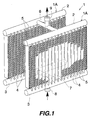
- FIG. 1 shows the overall construction of an evaporator as a first embodiment of the invention
- FIG. 2 shows the flow of refrigerant through the evaporator
- FIGS. 3 to 5 are fragmentary views showing main components of the evaporator.
- aluminum as used in the following description includes pure aluminum and other aluminum alloys.
- the evaporator 1 comprises two evaporator units 1A each including a pair of headers 2, 3 arranged one above the other in parallel and spaced apart by a distance, parallel flat refrigerant tubes 4 having a width oriented in the front-rear direction and opposite ends joined to the respective headers 2, 3, and a corrugated aluminum fin 5 disposed in an air passing clearance between each pair of refrigerant tubes 4 and brazed to the two tubes 4.
- the two evaporator units 1A are arranged in parallel as spaced apart in the front-rear direction.
- the upper headers 2 of the two evaporator units 1A are caused to communicate with each other and the lower headers 3 thereof are caused to communicate with each other by two communication pipes 6, 7, respectively.
- the communication pipes 6,7 are connected at their opposite ends to the lengthwise midportions of the two upper headers 2 and to the lengthwise midportions of the two lower headers 3, respectively.
- a refrigerant inlet pipe 8 is connected to the underside of the lengthwise midportion of the lower communication pipe 7.
- a refrigerant outlet pipe 9 is connected to the upper side of the lengthwise midportion of the upper communication pipe 6.
- each refrigerant tube 4 is in the form of a flat tube 17 of aluminum which comprises flat left and right walls 11, 12, front and rear walls 13, 14 positioned between and joined to the front and rear side edges of the left and right walls 11, 12, and a plurality of reinforcing walls 15 positioned between and joined to the left and right walls 11, 12, extending longitudinally thereof and arranged at a predetermined interval between the front and rear walls 13, 14.
- the tube 4 has parallel refrigerant channels 16 inside thereof.
- the left wall 11 of the flat tube 17 is formed on the inner surface thereof with a plurality of projections 18 projecting rightward from the left wall 11 integrally therewith and arranged longitudinally of the wall 11 at an interval so as to give an increased area of heat transfer.
- the reinforcing walls 15 are formed with a plurality of communication holes 19 for causing the parallel refrigerant channels 16 to communicate with one anther.
- the communication holes 19 are in a staggered arrangement when seen from the left. When the holes 19 are formed, the fluid flowing through the parallel fluid channels 16 also flows through the holes 19 transversely of the flat tube 17, spreading over all the fluid channels 16 to become stirred and eliminating any difference in the temperature of the fluid between the channels 16.
- Each of the reinforcing walls 15 is 10 to 40%, preferably 10 to 30%, more preferably about 20%, in opening ratio which is the ratio of all the communication holes 19 in the reinforcing wall 15 to the reinforcing wall.
- the communication holes 19 formed then result in a remarkable improvement in heat exchange efficiency.
- the flat aluminum tube 17 is formed by a left component 21 in the form of an aluminum plate and providing the left wall 11, front and rear walls 13, 14 and reinforcing walls 15; and a right component 22 in the form of an aluminum plate and providing the right wall 12, and front and rear walls 13, 14.
- the left component 21 comprises a left wall forming portion 23, rightward projecting walls 24 rightwardly projecting respectively from the front and rear side edges of the portion 23 integrally therewith, and reinforcing wall forming portions 25 inwardly projecting from the left wall forming portion 23 integrally therewith.
- a plurality of cutouts 26 are formed in the right edges of the reinforcing wall forming portions 25 and spaced apart at an interval longitudinally of the portions 25, the outer ends of the wall forming portions 25 are brazed to the right wall 12, and the openings of the cutouts 26 are closed with the right wall 12, whereby the communication holes 19 are formed.
- the left component 21 is externally formed at each of its front and rear side edges with a slope 27 slanting rightward externally of the front-rear direction.
- the right component 22 comprises a right wall forming portion 28, and leftward projecting walls 29 leftwardly projecting respectively from the front and rear side edges of the portion 28 integrally therewith.
- the leftward projecting walls 29 have an original height slightly greater than the height of the reinforcing wall forming portions 25 of the left component 21 plus the thickness of the left wall forming portion 23 (see the broken line in FIG. 4).
- the front and rear walls 13, 14 of the flat tube 17 are formed by the rightward projecting walls 24 of the left component 21 and the leftward projecting walls 29 of the right component 22.
- the left component 21 is prepared from an aluminum brazing sheet having a brazing material layer only on the outer side thereof.
- the right component 22 is prepared from an aluminum brazing sheet having a brazing material layer on each of opposite sides thereof.
- each left component 21 and the right component 22 are fitted to each other so that the leftward projecting walls 29 of the right component 22 are positioned outside of and lap over the respective rightward projecting walls 24 of the left component 21.
- the left end of each leftward projecting wall 29 is bent inward toward the front-rear direction, and the inward bent portion 29a is engaged with the slope 27 in intimate contact therewith, thereby the two components 21, 22 are tacked together.
- each rightward projecting wall 24 and the corresponding leftward projecting wall 29 are brazed to each other, the outer ends of the reinforcing wall forming portions 25 are brazed to the right wall forming portion 28, and each inward bent portion 29a is brazed to the respective slope 27 to form the flat tube 17.
- the left component 21 is formed by rolling.
- the right component 22 by roll forming.
- the left component 21 is rolled by a usual rolling mill.
- the left component 21 may be formed by a rolling mill which comprises a central work roll, and a plurality of planetary work rolls arranged around the central work roll, equidistantly spaced apart circumferentially thereof and rotatable at the same peripheral speed as the central work roll.
- the central work roll or each of the planetary work rolls is formed with rightward projecting wall forming annular grooves and reinforcing wall forming annular grooves in its peripheral surface over the entire circumference thereof.
- the ridge portion between each pair of adjacent reinforcing wall forming grooves is formed with projection forming cavities as arranged at a spacing circumferentially of the roll, and the bottom surface defining each reinforcing wall forming groove has cutout forming projections.
- the aluminum brazing sheet for the left component 21 is continuously passed between the central work roll and all the planetary work rolls, whereby the configurations of the grooves, cavities and projections are transferred to the sheet to give the left component 21 of the desired shape.
- FIGS. 6 and 7 show another evaporator 30 as a second embodiment of the invention.
- the evaporator 30 differs from the evaporator 1 according to the first embodiment in that a refrigerant inlet pipe 31 is connected to the upper side of the lengthwise midportion of the upper communication pipe 6, with a refrigerant outlet pipe 32 connected to the lower side of the lengthwise midportion of the lower communication pipe 7.
- the second embodiment has the same construction as the first.
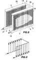
- FIGS. 8 and 9 show another evaporator 35, i.e., a third embodiment of the invention.
- the evaporator 35 comprises two evaporator units 1A, the upper headers 2 of which are interconnected at their right ends by a communication pipe 36 for holding the header right ends in communication with each other.
- the lower headers 3 of the two units 1A are held out of communication with each other.
- a refrigerant inlet pipe 37 is connected to the left end of lower header 3 of the rear evaporator unit 1A, and a refrigerant outlet pipe 38 is connected to the left end of lower header 3 of the front unit 1A.
- the third embodiment is the same as the first except this feature.
- the refrigerant flowing into the lower header 3 of the rear unit 1A through the inlet pipe 37 in a liquid phase flows upward through the refrigerant tubes 4 of the unit into the upper header 2, then flows into the upper header 2 of the front unit 1A by way of the communication pipe 36, subsequently flows down the refrigerant tubes 4 into the lower header 3 and flows out from the outlet pipe 38 in the form of a vapor phase.
- FIGS. 10 and 11 show another evaporator 40, i.e., a fourth embodiment of the invention.
- the evaporator 40 comprises two evaporator units 1A having upper and lower headers 2, 3.
- the upper headers 2 and the lower headers 3 are respectively interconnected at their left ends by communication pipes 41, 42 for communication.
- a refrigerant inlet pipe 43 is connected to the left side of lengthwise midportion of the lower communication pipe 42, with a refrigerant outlet pipe 44 connected to the left side of lengthwise mdiportion of the upper communication pipe 41.
- the fourth embodiment is the same as the first except this feature.
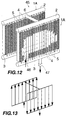
- FIGS. 12 and 13 show another evaporator 45, i.e., a fifth embodiment of the invention.
- the evaporator 45 comprises two evaporator units 1A, the upper headers 2 of which are held in communication with each other by a communication pipe 6 interconnecting the lengthwise midportions of these headers, while the lower headers 3 are held out of communication with each other.
- a refrigerant inlet pipe 46 is connected to the lower side of lengthwise midportion of the lower header 3 of the rear unit 1A, and a refrigerant outlet pipe 47 is connected to the lower side of lengthwise mirpotion of the lower header 3 of the front unit 1A.
- the fifth embodiment is the same as the first.
- the refrigerant flowing into the lower header 3 of the rear unit 1A through the inlet pipe 46 in a liquid phase flows upward through the refrigerant tubes 4 into the upper header 2, then flows into the upper header 2 of the front unit 1A via the communication pipe 6, subsequently flows down the tubes 4 into the lower header 3 and flows out from the outlet pipe 47 in the form of a vapor phase.
- FIGS. 14 and 15 show another evaporator 50, i.e., a sixth embodiment of the invention.
- the evaporator 50 comprises two evaporator units 1A, the upper headers 2 of which are held in communication with each other by a communication pipe 6 interconnecting the lengthwise midportions of the headers, with the lower headers 3 held out of communication.
- a refrigerant inlet pipe 51 is connected to the left end of the lower header 3 of the rear unit 1A, and a refrigerant outlet pipe 52 is connected to the left end of the lower header 3 of the front unit 1A.
- the sixth embodiment is the same as the first except this feature.
- the refrigerant flowing into the lower header 3 of the rear unit 1A via the inlet pipe 51 in a liquid phase flows upward through the refrigerant tubes 4 into the upper header 2, then flows into the upper header 2 of the front unit 1A through the communication pipe 6, thereafter flows down the refrigerant tubes 4 into the lower header 3 and flows out from the outlet pipe 52 in the form of a vapor phase.
- FIG. 16 shows another evaporator 55, i.e., a seventh embodiment of the invention.
- the evaporator 55 comprises a single evaporator unit 55A.
- the unit 55A comprises a pair of headers 56, 57 arranged one above the other in parallel and spaced apart by a distance, and a plurality of refrigerant tube groups 58 each including a plurality of, e.g., three, refrigerant tubes 4 arranged at a spacing in the front-rear direction and having a width oriented in this direction and opposite ends joined to the respective headers 56, 57.
- the tube groups 58 are arranged side by side at an interval in the left-right direction.
- the upper header 56 comprises a boxlike header body 59 opened downward, and a header plate 60 closing the lower opening.
- the refrigerant tubes 4 are joined at their upper ends to the header plate 60.
- the lower header 57 corresponds to the upper header 56 as turned upside down and has a header plate 60 with the lower ends of the tubes 4 joined thereto.
- the lower header 57 is provided at the lengthwise midportion thereof with a partition 61, which divides the interior of the lower header 57 in two.
- a refrigerant inlet pipe 62 is connected to the bottom wall of the lower header 57 at the right side of the partition 61, and a refrigerant outlet pipe 63 is connected to the bottom wall at the left side of the partition.
- the refrigerant flowing into the unit 55A at the right side of the partition 61 via the inlet pipe 62 in a liquid phase flows upward through all the tubes 4 at the right of the partition 61, then passes through the upper header 56, further flows into all the tubes 4 at the left of the partition 61, flows down these tubes into the lower header 57 at the left of the partition 61 and flows out via the outlet pipe 63 in a vapor phase.
- the evaporator 55 of the seventh embodiment was used in this example.
- the evaporator 55 was 227 mm in length L in the left-right direction, 60 mm in width W in the front-rear direction, and 235 mm in height H.
- the flat tube 17 serving as each refrigerant tube 4 was 18 mm in width in the front-rear direction and 1.7 mm in thickness in the left-right direction.
- the tube groups 58 each comprising three refrigerant tubes 4 was 22 in number.
- the air-side heat transfer area A (m 2 ) and the refrigerant-side heat transfer area B (m 2 ) were determined.
- HFC134a the quantity of heat exchange, Q (kcal/h), and the air-side resistance to the passage of air, ⁇ Pa (wet) (mm Aq)
- ⁇ Pa the air-side resistance to the passage of air
- An evaporator was used which comprised refrigerant tubes of hollow aluminum extrudate in place of the flat refrigerant tubes used in the above example.
- the size of the evaporator was the same as the one used in the above example, the refrigerant tubes of hollow extrudate were of the same size as the flat tubes of the example.
- the air-side heat transfer area A (m 2 ) and the refrigerant-side heat transfer area B (m 2 ) were determined.
- the quantity of heat exchange, Q (kcal/h), and the air-side resistance to the passage of air, ⁇ Pa (wet) (mm Aq) were measured under the same conditions as in the foregoing example.
- the air-side heat transfer area A (m 2 ) and the refrigerant-side heat transfer area B (m 2 ) were determined.
- the quantity of heat exchange, Q (kcal/h), and the air-side resistance to the passage of air, ⁇ Pa (wet) (mm Aq) were measured under the same conditions as in the foregoing example.
- the table reveals that the evaporator of Example 1 is equivalent to the evaporator of Comparative Example 2 in the quantity of heat exchange although smaller in width and smaller in its entirety, presumably because the former has an increased heat transfer area on the refrigerant side although smaller than the latter in width in the front-rear direction. Furthermore, the evaporator of Example 1 is smaller than that of Comparative Example 2 in air-side resistance to the passage of air, consequently permitting passage of an larger amount of air and leading to an increased quantity of heat exchange. The evaporator of Comparative Example 1, is smaller than that of Example 1 in the quantity of heat exchange although of the same size as the evaporator of Example 1. This appears attributable to the smaller refrigerant-side heat transfer area of the comparative evaporator and to the absence of the communication holes formed in the reinforcing walls for holding the parallel channels in communication with one another.
- the refrigerant tube 4 of Example 1 was used to determine the relationship between the average quality of the refrigerant (mass proportion of the vapor in the refrigerant) X (%) and the heat transfer coefficient h by the following method.
- the refrigerant tube was disposed in a cooling water channel, and HFC134a serving as the refrigerant was passed through the tube, with cooling water caused to flow through the channel.
- the heat transfer coefficient h was measured at varying average quality values of the refrigerant under the conditions of: refrigerant flow rate, 400 kg/m 2 ⁇ s; heat flux between refrigerant and cooling water, 8 kW/m 2 ; refrigerant saturation temperature T, 40 deg C; and cooling water flow rate to give a Reynolds number of 1500.
- the refrigerant tube of Comparative Example 1 was used to establish the relationship between the average quality of the refrigerant, HFC134a, X (%) and the heat transfer coefficient h by the same method as in Example 2.
- FIG. 17 shows the results of Example 2 and Comparative Example 3.
- FIG. 17 reveals that Example 2 involving an increased refrigerant-side heat transfer area and the presence of communication holes formed in the reinforcing walls is greater in heat transfer coefficient h than Comparative Example 3 which is small in refrigerant-side heat transfer area and has no communication holes.
Abstract
Description
| A | B | Q | ΔPa (wet) | |
| Example | 77 | 137 | 100 | 66 |
| Comp. Ex. 1 | 77 | 116 | 88 | 72 |
| Comp. Ex. 2 | 100 | 100 | 100 | 100 |
Claims (11)
- An evaporator comprising at least one evaporator unit including a pair of headers arranged one above the other in parallel and spaced apart by a distance, and parallel refrigerant tubes having a width oriented in a front-rear direction and opposite ends joined to the respect headers, each of the refrigerant tubes being in the form of a flat tube comprising flat left and right walls, front and rear walls positioned between and joined to front and rear side edges of the left and right walls, and a plurality of reinforcing walls positioned between and joined to the left and right walls and extending longitudinally thereof, the reinforcing walls being arranged at a predetermined interval between the front and rear walls, the flat tube having parallel refrigerant channels inside thereof and being formed from a metal plate, each of the reinforcing walls comprising a reinforcing wall forming portion inwardly projecting from the metal plate integrally therewith.
- An evaporator according to claim 1 wherein the reinforcing walls are formed with a plurality of communication holes for causing the parallel refrigerant channels to communicate with one another.
- An evaporator according to claim 2 wherein the communication holes are in a staggered arrangement when seen from the left.
- An evaporator according to claim 2 or 3 wherein each of the reinforcing walls is 10 to 40% in opening ratio which is the ratio of all the communication holes in the reinforcing wall to the reinforcing wall.
- An evaporator according to claim 1 wherein two evaporator units are arranged in parallel as spaced apart in the front-rear direction, and the upper headers of the two evaporator units are caused to communicate with each other and the lower headers thereof are caused to communicate with each other by two communication pipes respectively, a refrigerant inlet pipe being connected to one of the communication pipes, a refrigerant outlet pipe being connected to the other communication pipe.
- An evaporator according to claim 1 wherein two evaporator units are arranged in parallel as spaced apart in the front-rear direction, and the upper headers of the two evaporator units are caused to communicate with each other by a communication pipe, a refrigerant inlet pipe being connected to the lower head of one of the evaporator units, a refrigerant outlet pipe being connected to the lower header of the other evaporator unit.
- An evaporator according to claim 1 wherein the evaporator unit comprises a plurality of refrigerant tube groups each comprising a plurality of refrigerant tubes arranged at an interval in the front-rear direction, and the refrigerant tube groups are arranged side by side in a left-right direction.
- An evaporator according to claim 1 wherein the flat tube is formed by a platelike left component having a left wall forming portion and a platelike right component having a right wall forming portion, and each of the front and rear walls of the flat tube comprises at least one of a rightward projecting wall projecting rightward from each of front and rear side edges of the left component integrally therewith and brazed to the right component and a leftward projecting wall projecting leftward from each of front and rear side edges of the right component integrally therewith and brazed to the left component, each of the reinforcing walls of the flat tube comprising a reinforcing wall forming portion projecting inward from at least one of the left wall forming portion of the left component and the right wall forming portion of the right component integrally therewith and having an outer end brazed to the other wall forming portion.
- An evaporator according to claim 8 wherein the reinforcing walls are formed with a plurality of communication holes for causing the parallel refrigerant channels to communicate with one another.
- An evaporator according to claim 9 wherein the communication holes are in a staggered arrangement when seen from the left.
- An evaporator according to claim 9 or 10 wherein each of the reinforcing walls is 10 to 40% in opening ratio which is the ratio of all the communication holes in the reinforcing wall to the reinforcing wall.
Applications Claiming Priority (3)
| Application Number | Priority Date | Filing Date | Title |
|---|---|---|---|
| JP28235996 | 1996-10-24 | ||
| JP282359/96 | 1996-10-24 | ||
| JP28235996 | 1996-10-24 |
Publications (3)
| Publication Number | Publication Date |
|---|---|
| EP0838641A2 true EP0838641A2 (en) | 1998-04-29 |
| EP0838641A3 EP0838641A3 (en) | 1999-09-22 |
| EP0838641B1 EP0838641B1 (en) | 2004-07-14 |
Family
ID=17651388
Family Applications (1)
| Application Number | Title | Priority Date | Filing Date |
|---|---|---|---|
| EP97118435A Expired - Lifetime EP0838641B1 (en) | 1996-10-24 | 1997-10-23 | Evaporator |
Country Status (6)
| Country | Link |
|---|---|
| EP (1) | EP0838641B1 (en) |
| KR (1) | KR100497847B1 (en) |
| AT (1) | ATE271210T1 (en) |
| AU (1) | AU4282097A (en) |
| CZ (1) | CZ336097A3 (en) |
| DE (1) | DE69729836T2 (en) |
Cited By (15)
| Publication number | Priority date | Publication date | Assignee | Title |
|---|---|---|---|---|
| WO2000006964A1 (en) * | 1998-07-28 | 2000-02-10 | Ford-Werke Aktiengesellschaft | Heat exchanger tubular block and a multi-chamber flat tube which can be used therefor |
| FR2793013A1 (en) * | 1999-04-28 | 2000-11-03 | Valeo Thermique Moteur Sa | Heat exchanger assembly for an automobile, utilises a cross flow configuration between the fluid supply and sump assemblies via tubular plate type heat exchange fins |
| AU740183B2 (en) * | 1999-05-31 | 2001-11-01 | Mitsubishi Heavy Industries, Ltd. | Heat exchanger |
| US6938685B2 (en) | 2001-05-11 | 2005-09-06 | Behr Gmbh & Co. | Heat exchanger |
| WO2007037670A1 (en) * | 2005-09-30 | 2007-04-05 | Seasonair (M) Sdn Bhd | Heat exchanger |
| EP2253493A2 (en) * | 2009-05-18 | 2010-11-24 | Behr GmbH & Co. KG | Device for heating the interior of a motor vehicle |
| WO2012068200A1 (en) * | 2010-11-19 | 2012-05-24 | Modine Manufacturing Company | Heat exchanger assembly and method |
| CN104335000A (en) * | 2012-04-26 | 2015-02-04 | 三菱电机株式会社 | Heat exchanger and heat exchange method |
| DE10220533B4 (en) * | 2001-05-11 | 2016-06-02 | Mahle International Gmbh | heat exchangers |
| US20160298886A1 (en) * | 2013-07-08 | 2016-10-13 | Mitsubishi Electric Corporation | Heat exchanger and heat pump apparatus |
| TWI631308B (en) * | 2017-09-14 | 2018-08-01 | 萬在工業股份有限公司 | Parallel condenser and heat sink |
| EP3279599A4 (en) * | 2015-03-31 | 2018-11-07 | GD Midea Heating & Ventilating Equipment Co., Ltd. | Heat exchanger and multi-split system having same |
| WO2019134967A1 (en) * | 2018-01-08 | 2019-07-11 | Valeo Systemes Thermiques | Heat exchange device and method and system including that kind of device for thermal management of a battery |
| CN113167512A (en) * | 2018-12-19 | 2021-07-23 | 三菱电机株式会社 | Heat exchanger and refrigeration cycle device |
| WO2023030974A1 (en) * | 2021-09-03 | 2023-03-09 | Valeo Systemes Thermiques | Heat exchanger for refrigerant loop |
Families Citing this family (1)
| Publication number | Priority date | Publication date | Assignee | Title |
|---|---|---|---|---|
| CN101398274B (en) * | 2007-09-29 | 2012-07-25 | 卡特彼勒公司 | Heat exchanger tube assembly welded by laser |
Citations (1)
| Publication number | Priority date | Publication date | Assignee | Title |
|---|---|---|---|---|
| JPH03230064A (en) | 1990-02-06 | 1991-10-14 | Showa Alum Corp | Laminated type evaporator |
Family Cites Families (12)
| Publication number | Priority date | Publication date | Assignee | Title |
|---|---|---|---|---|
| DE873921C (en) * | 1941-01-30 | 1953-04-20 | Artur Dietz | Cooler |
| JPH02140166U (en) * | 1989-04-24 | 1990-11-22 | ||
| CA2035590A1 (en) * | 1990-02-12 | 1991-08-13 | Gregory G. Hughes | Multipass evaporator |
| JPH0534460U (en) * | 1991-10-07 | 1993-05-07 | 株式会社神戸製鋼所 | Open rack heat exchanger |
| JP3364665B2 (en) * | 1993-03-26 | 2003-01-08 | 昭和電工株式会社 | Refrigerant flow pipe for heat exchanger |
| US5323851A (en) * | 1993-04-21 | 1994-06-28 | Wynn's Climate Systems, Inc. | Parallel flow condenser with perforated webs |
| JP3151505B2 (en) * | 1994-09-28 | 2001-04-03 | 昭和アルミニウム株式会社 | Stacked heat exchanger |
| JP3216438B2 (en) * | 1994-09-16 | 2001-10-09 | 株式会社日立製作所 | Heat exchanger for heat dissipation of refrigerator |
| JPH08178569A (en) * | 1994-12-28 | 1996-07-12 | Showa Alum Corp | Manufacture of refrigerant flow tube for heat exchanger |
| JPH0926278A (en) * | 1995-07-07 | 1997-01-28 | Showa Alum Corp | Heat exchanger refrigerant flow pipe and car air-conditioner condenser |
| US5771964A (en) * | 1996-04-19 | 1998-06-30 | Heatcraft Inc. | Heat exchanger with relatively flat fluid conduits |
| EP0815971B1 (en) * | 1996-06-26 | 2002-09-04 | Showa Denko K.K. | Process for producing flat heat exchange tubes |
-
1997
- 1997-10-20 KR KR1019970053676A patent/KR100497847B1/en not_active IP Right Cessation
- 1997-10-23 DE DE69729836T patent/DE69729836T2/en not_active Expired - Fee Related
- 1997-10-23 AT AT97118435T patent/ATE271210T1/en not_active IP Right Cessation
- 1997-10-23 AU AU42820/97A patent/AU4282097A/en not_active Abandoned
- 1997-10-23 CZ CZ973360A patent/CZ336097A3/en unknown
- 1997-10-23 EP EP97118435A patent/EP0838641B1/en not_active Expired - Lifetime
Patent Citations (1)
| Publication number | Priority date | Publication date | Assignee | Title |
|---|---|---|---|---|
| JPH03230064A (en) | 1990-02-06 | 1991-10-14 | Showa Alum Corp | Laminated type evaporator |
Cited By (25)
| Publication number | Priority date | Publication date | Assignee | Title |
|---|---|---|---|---|
| US6523606B1 (en) | 1998-07-28 | 2003-02-25 | Visteon Global Technologies, Inc. | Heat exchanger tube block with multichamber flat tubes |
| WO2000006964A1 (en) * | 1998-07-28 | 2000-02-10 | Ford-Werke Aktiengesellschaft | Heat exchanger tubular block and a multi-chamber flat tube which can be used therefor |
| FR2793013A1 (en) * | 1999-04-28 | 2000-11-03 | Valeo Thermique Moteur Sa | Heat exchanger assembly for an automobile, utilises a cross flow configuration between the fluid supply and sump assemblies via tubular plate type heat exchange fins |
| AU740183B2 (en) * | 1999-05-31 | 2001-11-01 | Mitsubishi Heavy Industries, Ltd. | Heat exchanger |
| DE10220533B4 (en) * | 2001-05-11 | 2016-06-02 | Mahle International Gmbh | heat exchangers |
| US6938685B2 (en) | 2001-05-11 | 2005-09-06 | Behr Gmbh & Co. | Heat exchanger |
| WO2007037670A1 (en) * | 2005-09-30 | 2007-04-05 | Seasonair (M) Sdn Bhd | Heat exchanger |
| EP2253493A2 (en) * | 2009-05-18 | 2010-11-24 | Behr GmbH & Co. KG | Device for heating the interior of a motor vehicle |
| EP2253493A3 (en) * | 2009-05-18 | 2011-06-29 | Behr GmbH & Co. KG | Device for heating the interior of a motor vehicle |
| WO2012068200A1 (en) * | 2010-11-19 | 2012-05-24 | Modine Manufacturing Company | Heat exchanger assembly and method |
| CN103221773A (en) * | 2010-11-19 | 2013-07-24 | 摩丁制造公司 | Heat exchanger assembly and method |
| CN104335000B (en) * | 2012-04-26 | 2016-09-14 | 三菱电机株式会社 | Heat exchanger and heat change method |
| CN104335000A (en) * | 2012-04-26 | 2015-02-04 | 三菱电机株式会社 | Heat exchanger and heat exchange method |
| US20160298886A1 (en) * | 2013-07-08 | 2016-10-13 | Mitsubishi Electric Corporation | Heat exchanger and heat pump apparatus |
| EP3021064A4 (en) * | 2013-07-08 | 2017-03-22 | Mitsubishi Electric Corporation | Heat exchanger, and heat pump device |
| EP3279599A4 (en) * | 2015-03-31 | 2018-11-07 | GD Midea Heating & Ventilating Equipment Co., Ltd. | Heat exchanger and multi-split system having same |
| TWI631308B (en) * | 2017-09-14 | 2018-08-01 | 萬在工業股份有限公司 | Parallel condenser and heat sink |
| FR3076604A1 (en) * | 2018-01-08 | 2019-07-12 | Valeo Systemes Thermiques | THERMAL EXCHANGE DEVICE AND SYSTEM AND METHOD FOR THERMALLY MANAGING A BATTERY COMPRISING SUCH A DEVICE |
| WO2019134967A1 (en) * | 2018-01-08 | 2019-07-11 | Valeo Systemes Thermiques | Heat exchange device and method and system including that kind of device for thermal management of a battery |
| CN113167512A (en) * | 2018-12-19 | 2021-07-23 | 三菱电机株式会社 | Heat exchanger and refrigeration cycle device |
| EP3901536A4 (en) * | 2018-12-19 | 2021-12-08 | Mitsubishi Electric Corporation | Heat exchanger and refrigeration cycle device |
| CN113167512B (en) * | 2018-12-19 | 2023-02-28 | 三菱电机株式会社 | Heat exchanger and refrigeration cycle device |
| US11885512B2 (en) | 2018-12-19 | 2024-01-30 | Mitsubishi Electric Corporation | Heat exchanger and refrigeration cycle device |
| WO2023030974A1 (en) * | 2021-09-03 | 2023-03-09 | Valeo Systemes Thermiques | Heat exchanger for refrigerant loop |
| FR3126763A1 (en) * | 2021-09-03 | 2023-03-10 | Valeo Systemes Thermiques | HEAT EXCHANGER FOR REFRIGERANT LOOP |
Also Published As
| Publication number | Publication date |
|---|---|
| DE69729836D1 (en) | 2004-08-19 |
| ATE271210T1 (en) | 2004-07-15 |
| KR100497847B1 (en) | 2005-09-30 |
| DE69729836T2 (en) | 2005-07-07 |
| EP0838641B1 (en) | 2004-07-14 |
| EP0838641A3 (en) | 1999-09-22 |
| KR19980032970A (en) | 1998-07-25 |
| AU4282097A (en) | 1998-04-30 |
| CZ336097A3 (en) | 1998-06-17 |
Similar Documents
| Publication | Publication Date | Title |
|---|---|---|
| EP0838641B1 (en) | Evaporator | |
| US7886812B2 (en) | Heat exchanger having a tank partition wall | |
| US5318114A (en) | Multi-layered type heat exchanger | |
| US5984000A (en) | Layered heat exchangers | |
| US7726387B2 (en) | Heat exchangers | |
| US7635019B2 (en) | Heat exchanger | |
| US20070277964A1 (en) | Heat exchange tube and evaporator | |
| US7992401B2 (en) | Evaporator | |
| US20060016583A1 (en) | Condenser and tube therefor | |
| EP1692449B1 (en) | Evaporator and process for fabricating same | |
| US20080053137A1 (en) | Heat Exchanger | |
| US20010029748A1 (en) | Condenser for a vehicle air-conditioning system | |
| EP1370818A1 (en) | Heat exchanger | |
| JP2004530092A5 (en) | ||
| US5931226A (en) | Refrigerant tubes for heat exchangers | |
| JP4625687B2 (en) | Heat exchanger | |
| EP0762070B1 (en) | Refrigerant tubes for heat exchangers | |
| US7174953B2 (en) | Stacking-type, multi-flow, heat exchanger | |
| US20040050531A1 (en) | Heat exchanger | |
| JP3661275B2 (en) | Stacked evaporator | |
| US20120198882A1 (en) | Evaporator | |
| US6446715B2 (en) | Flat heat exchange tubes | |
| JPH10185358A (en) | Evaporator | |
| JPH10157447A (en) | Heat exchanger | |
| JPH0712775U (en) | Stacked heat exchanger |
Legal Events
| Date | Code | Title | Description |
|---|---|---|---|
| PUAI | Public reference made under article 153(3) epc to a published international application that has entered the european phase |
Free format text: ORIGINAL CODE: 0009012 |
|
| AK | Designated contracting states |
Kind code of ref document: A2 Designated state(s): AT BE DE ES FR GB NL SE |
|
| AX | Request for extension of the european patent |
Free format text: AL;LT;LV;RO;SI |
|
| PUAL | Search report despatched |
Free format text: ORIGINAL CODE: 0009013 |
|
| AK | Designated contracting states |
Kind code of ref document: A3 Designated state(s): AT BE CH DE DK ES FI FR GB GR IE IT LI LU MC NL PT SE |
|
| AX | Request for extension of the european patent |
Free format text: AL;LT;LV;RO;SI |
|
| RIC1 | Information provided on ipc code assigned before grant |
Free format text: 6F 25B 39/02 A, 6F 28D 1/03 B, 6F 28F 3/04 B, 6F 28F 9/26 B |
|
| 17P | Request for examination filed |
Effective date: 19991125 |
|
| AKX | Designation fees paid |
Free format text: AT BE DE ES FR GB NL SE |
|
| RAP1 | Party data changed (applicant data changed or rights of an application transferred) |
Owner name: SHOWA DENKO K K |
|
| RAP1 | Party data changed (applicant data changed or rights of an application transferred) |
Owner name: SHOWA DENKO K.K. |
|
| 17Q | First examination report despatched |
Effective date: 20020503 |
|
| GRAP | Despatch of communication of intention to grant a patent |
Free format text: ORIGINAL CODE: EPIDOSNIGR1 |
|
| GRAS | Grant fee paid |
Free format text: ORIGINAL CODE: EPIDOSNIGR3 |
|
| GRAA | (expected) grant |
Free format text: ORIGINAL CODE: 0009210 |
|
| AK | Designated contracting states |
Kind code of ref document: B1 Designated state(s): AT BE DE ES FR GB NL SE |
|
| PG25 | Lapsed in a contracting state [announced via postgrant information from national office to epo] |
Ref country code: NL Free format text: LAPSE BECAUSE OF FAILURE TO SUBMIT A TRANSLATION OF THE DESCRIPTION OR TO PAY THE FEE WITHIN THE PRESCRIBED TIME-LIMIT Effective date: 20040714 Ref country code: BE Free format text: LAPSE BECAUSE OF FAILURE TO SUBMIT A TRANSLATION OF THE DESCRIPTION OR TO PAY THE FEE WITHIN THE PRESCRIBED TIME-LIMIT Effective date: 20040714 Ref country code: AT Free format text: LAPSE BECAUSE OF FAILURE TO SUBMIT A TRANSLATION OF THE DESCRIPTION OR TO PAY THE FEE WITHIN THE PRESCRIBED TIME-LIMIT Effective date: 20040714 |
|
| REG | Reference to a national code |
Ref country code: GB Ref legal event code: FG4D |
|
| REF | Corresponds to: |
Ref document number: 69729836 Country of ref document: DE Date of ref document: 20040819 Kind code of ref document: P |
|
| PG25 | Lapsed in a contracting state [announced via postgrant information from national office to epo] |
Ref country code: SE Free format text: LAPSE BECAUSE OF FAILURE TO SUBMIT A TRANSLATION OF THE DESCRIPTION OR TO PAY THE FEE WITHIN THE PRESCRIBED TIME-LIMIT Effective date: 20041014 |
|
| PG25 | Lapsed in a contracting state [announced via postgrant information from national office to epo] |
Ref country code: ES Free format text: LAPSE BECAUSE OF FAILURE TO SUBMIT A TRANSLATION OF THE DESCRIPTION OR TO PAY THE FEE WITHIN THE PRESCRIBED TIME-LIMIT Effective date: 20041025 |
|
| NLV1 | Nl: lapsed or annulled due to failure to fulfill the requirements of art. 29p and 29m of the patents act | ||
| ET | Fr: translation filed | ||
| PLBE | No opposition filed within time limit |
Free format text: ORIGINAL CODE: 0009261 |
|
| STAA | Information on the status of an ep patent application or granted ep patent |
Free format text: STATUS: NO OPPOSITION FILED WITHIN TIME LIMIT |
|
| 26N | No opposition filed |
Effective date: 20050415 |
|
| PGFP | Annual fee paid to national office [announced via postgrant information from national office to epo] |
Ref country code: GB Payment date: 20061018 Year of fee payment: 10 |
|
| GBPC | Gb: european patent ceased through non-payment of renewal fee |
Effective date: 20071023 |
|
| REG | Reference to a national code |
Ref country code: FR Ref legal event code: ST Effective date: 20080630 |
|
| PGFP | Annual fee paid to national office [announced via postgrant information from national office to epo] |
Ref country code: FR Payment date: 20061010 Year of fee payment: 10 |
|
| PG25 | Lapsed in a contracting state [announced via postgrant information from national office to epo] |
Ref country code: GB Free format text: LAPSE BECAUSE OF NON-PAYMENT OF DUE FEES Effective date: 20071023 |
|
| PGFP | Annual fee paid to national office [announced via postgrant information from national office to epo] |
Ref country code: DE Payment date: 20081016 Year of fee payment: 12 |
|
| PG25 | Lapsed in a contracting state [announced via postgrant information from national office to epo] |
Ref country code: FR Free format text: LAPSE BECAUSE OF NON-PAYMENT OF DUE FEES Effective date: 20071031 |
|
| PG25 | Lapsed in a contracting state [announced via postgrant information from national office to epo] |
Ref country code: DE Free format text: LAPSE BECAUSE OF NON-PAYMENT OF DUE FEES Effective date: 20100501 |