EP0762070B1 - Refrigerant tubes for heat exchangers - Google Patents
Refrigerant tubes for heat exchangers Download PDFInfo
- Publication number
- EP0762070B1 EP0762070B1 EP96110844A EP96110844A EP0762070B1 EP 0762070 B1 EP0762070 B1 EP 0762070B1 EP 96110844 A EP96110844 A EP 96110844A EP 96110844 A EP96110844 A EP 96110844A EP 0762070 B1 EP0762070 B1 EP 0762070B1
- Authority
- EP
- European Patent Office
- Prior art keywords
- tube
- refrigerant
- walls
- reinforcing
- communication holes
- Prior art date
- Legal status (The legal status is an assumption and is not a legal conclusion. Google has not performed a legal analysis and makes no representation as to the accuracy of the status listed.)
- Expired - Lifetime
Links
- 239000003507 refrigerant Substances 0.000 title claims description 114
- 230000003014 reinforcing effect Effects 0.000 claims description 42
- 229910052782 aluminium Inorganic materials 0.000 claims description 40
- XAGFODPZIPBFFR-UHFFFAOYSA-N aluminium Chemical compound [Al] XAGFODPZIPBFFR-UHFFFAOYSA-N 0.000 claims description 40
- 238000004891 communication Methods 0.000 claims description 32
- 238000005219 brazing Methods 0.000 claims description 10
- 239000000945 filler Substances 0.000 claims description 4
- 229910052751 metal Inorganic materials 0.000 claims description 4
- 239000002184 metal Substances 0.000 claims description 4
- 238000005192 partition Methods 0.000 description 34
- 238000011156 evaluation Methods 0.000 description 13
- 238000012360 testing method Methods 0.000 description 13
- 238000012546 transfer Methods 0.000 description 10
- 230000000052 comparative effect Effects 0.000 description 8
- 238000000034 method Methods 0.000 description 7
- 238000005096 rolling process Methods 0.000 description 5
- 238000005452 bending Methods 0.000 description 4
- 239000000498 cooling water Substances 0.000 description 4
- 238000007373 indentation Methods 0.000 description 3
- 238000010276 construction Methods 0.000 description 2
- 238000001816 cooling Methods 0.000 description 2
- 230000003247 decreasing effect Effects 0.000 description 2
- 210000001503 joint Anatomy 0.000 description 2
- 239000007791 liquid phase Substances 0.000 description 2
- 230000002093 peripheral effect Effects 0.000 description 2
- 238000011144 upstream manufacturing Methods 0.000 description 2
- 229910000838 Al alloy Inorganic materials 0.000 description 1
- 239000003990 capacitor Substances 0.000 description 1
- 230000005494 condensation Effects 0.000 description 1
- 238000009833 condensation Methods 0.000 description 1
- 230000004907 flux Effects 0.000 description 1
- 230000001771 impaired effect Effects 0.000 description 1
- 239000007788 liquid Substances 0.000 description 1
- 239000012071 phase Substances 0.000 description 1
- 229910000679 solder Inorganic materials 0.000 description 1
- 239000012808 vapor phase Substances 0.000 description 1
Images


Classifications
-
- F—MECHANICAL ENGINEERING; LIGHTING; HEATING; WEAPONS; BLASTING
- F28—HEAT EXCHANGE IN GENERAL
- F28F—DETAILS OF HEAT-EXCHANGE AND HEAT-TRANSFER APPARATUS, OF GENERAL APPLICATION
- F28F3/00—Plate-like or laminated elements; Assemblies of plate-like or laminated elements
- F28F3/02—Elements or assemblies thereof with means for increasing heat-transfer area, e.g. with fins, with recesses, with corrugations
- F28F3/04—Elements or assemblies thereof with means for increasing heat-transfer area, e.g. with fins, with recesses, with corrugations the means being integral with the element
- F28F3/048—Elements or assemblies thereof with means for increasing heat-transfer area, e.g. with fins, with recesses, with corrugations the means being integral with the element in the form of ribs integral with the element or local variations in thickness of the element, e.g. grooves, microchannels
-
- F—MECHANICAL ENGINEERING; LIGHTING; HEATING; WEAPONS; BLASTING
- F28—HEAT EXCHANGE IN GENERAL
- F28F—DETAILS OF HEAT-EXCHANGE AND HEAT-TRANSFER APPARATUS, OF GENERAL APPLICATION
- F28F9/00—Casings; Header boxes; Auxiliary supports for elements; Auxiliary members within casings
-
- B—PERFORMING OPERATIONS; TRANSPORTING
- B21—MECHANICAL METAL-WORKING WITHOUT ESSENTIALLY REMOVING MATERIAL; PUNCHING METAL
- B21C—MANUFACTURE OF METAL SHEETS, WIRE, RODS, TUBES OR PROFILES, OTHERWISE THAN BY ROLLING; AUXILIARY OPERATIONS USED IN CONNECTION WITH METAL-WORKING WITHOUT ESSENTIALLY REMOVING MATERIAL
- B21C23/00—Extruding metal; Impact extrusion
- B21C23/02—Making uncoated products
- B21C23/04—Making uncoated products by direct extrusion
- B21C23/08—Making wire, bars, tubes
- B21C23/10—Making finned tubes
-
- B—PERFORMING OPERATIONS; TRANSPORTING
- B21—MECHANICAL METAL-WORKING WITHOUT ESSENTIALLY REMOVING MATERIAL; PUNCHING METAL
- B21C—MANUFACTURE OF METAL SHEETS, WIRE, RODS, TUBES OR PROFILES, OTHERWISE THAN BY ROLLING; AUXILIARY OPERATIONS USED IN CONNECTION WITH METAL-WORKING WITHOUT ESSENTIALLY REMOVING MATERIAL
- B21C37/00—Manufacture of metal sheets, bars, wire, tubes or like semi-manufactured products, not otherwise provided for; Manufacture of tubes of special shape
- B21C37/06—Manufacture of metal sheets, bars, wire, tubes or like semi-manufactured products, not otherwise provided for; Manufacture of tubes of special shape of tubes or metal hoses; Combined procedures for making tubes, e.g. for making multi-wall tubes
- B21C37/15—Making tubes of special shape; Making tube fittings
- B21C37/151—Making tubes with multiple passages
-
- F—MECHANICAL ENGINEERING; LIGHTING; HEATING; WEAPONS; BLASTING
- F28—HEAT EXCHANGE IN GENERAL
- F28D—HEAT-EXCHANGE APPARATUS, NOT PROVIDED FOR IN ANOTHER SUBCLASS, IN WHICH THE HEAT-EXCHANGE MEDIA DO NOT COME INTO DIRECT CONTACT
- F28D1/00—Heat-exchange apparatus having stationary conduit assemblies for one heat-exchange medium only, the media being in contact with different sides of the conduit wall, in which the other heat-exchange medium is a large body of fluid, e.g. domestic or motor car radiators
- F28D1/02—Heat-exchange apparatus having stationary conduit assemblies for one heat-exchange medium only, the media being in contact with different sides of the conduit wall, in which the other heat-exchange medium is a large body of fluid, e.g. domestic or motor car radiators with heat-exchange conduits immersed in the body of fluid
- F28D1/03—Heat-exchange apparatus having stationary conduit assemblies for one heat-exchange medium only, the media being in contact with different sides of the conduit wall, in which the other heat-exchange medium is a large body of fluid, e.g. domestic or motor car radiators with heat-exchange conduits immersed in the body of fluid with plate-like or laminated conduits
- F28D1/0308—Heat-exchange apparatus having stationary conduit assemblies for one heat-exchange medium only, the media being in contact with different sides of the conduit wall, in which the other heat-exchange medium is a large body of fluid, e.g. domestic or motor car radiators with heat-exchange conduits immersed in the body of fluid with plate-like or laminated conduits the conduits being formed by paired plates touching each other
- F28D1/0316—Assemblies of conduits in parallel
-
- F—MECHANICAL ENGINEERING; LIGHTING; HEATING; WEAPONS; BLASTING
- F28—HEAT EXCHANGE IN GENERAL
- F28D—HEAT-EXCHANGE APPARATUS, NOT PROVIDED FOR IN ANOTHER SUBCLASS, IN WHICH THE HEAT-EXCHANGE MEDIA DO NOT COME INTO DIRECT CONTACT
- F28D1/00—Heat-exchange apparatus having stationary conduit assemblies for one heat-exchange medium only, the media being in contact with different sides of the conduit wall, in which the other heat-exchange medium is a large body of fluid, e.g. domestic or motor car radiators
- F28D1/02—Heat-exchange apparatus having stationary conduit assemblies for one heat-exchange medium only, the media being in contact with different sides of the conduit wall, in which the other heat-exchange medium is a large body of fluid, e.g. domestic or motor car radiators with heat-exchange conduits immersed in the body of fluid
- F28D1/03—Heat-exchange apparatus having stationary conduit assemblies for one heat-exchange medium only, the media being in contact with different sides of the conduit wall, in which the other heat-exchange medium is a large body of fluid, e.g. domestic or motor car radiators with heat-exchange conduits immersed in the body of fluid with plate-like or laminated conduits
- F28D1/0391—Heat-exchange apparatus having stationary conduit assemblies for one heat-exchange medium only, the media being in contact with different sides of the conduit wall, in which the other heat-exchange medium is a large body of fluid, e.g. domestic or motor car radiators with heat-exchange conduits immersed in the body of fluid with plate-like or laminated conduits a single plate being bent to form one or more conduits
-
- F—MECHANICAL ENGINEERING; LIGHTING; HEATING; WEAPONS; BLASTING
- F28—HEAT EXCHANGE IN GENERAL
- F28D—HEAT-EXCHANGE APPARATUS, NOT PROVIDED FOR IN ANOTHER SUBCLASS, IN WHICH THE HEAT-EXCHANGE MEDIA DO NOT COME INTO DIRECT CONTACT
- F28D7/00—Heat-exchange apparatus having stationary tubular conduit assemblies for both heat-exchange media, the media being in contact with different sides of a conduit wall
-
- F—MECHANICAL ENGINEERING; LIGHTING; HEATING; WEAPONS; BLASTING
- F28—HEAT EXCHANGE IN GENERAL
- F28F—DETAILS OF HEAT-EXCHANGE AND HEAT-TRANSFER APPARATUS, OF GENERAL APPLICATION
- F28F3/00—Plate-like or laminated elements; Assemblies of plate-like or laminated elements
-
- F—MECHANICAL ENGINEERING; LIGHTING; HEATING; WEAPONS; BLASTING
- F28—HEAT EXCHANGE IN GENERAL
- F28D—HEAT-EXCHANGE APPARATUS, NOT PROVIDED FOR IN ANOTHER SUBCLASS, IN WHICH THE HEAT-EXCHANGE MEDIA DO NOT COME INTO DIRECT CONTACT
- F28D21/00—Heat-exchange apparatus not covered by any of the groups F28D1/00 - F28D20/00
- F28D2021/0019—Other heat exchangers for particular applications; Heat exchange systems not otherwise provided for
- F28D2021/0068—Other heat exchangers for particular applications; Heat exchange systems not otherwise provided for for refrigerant cycles
- F28D2021/0071—Evaporators
-
- F—MECHANICAL ENGINEERING; LIGHTING; HEATING; WEAPONS; BLASTING
- F28—HEAT EXCHANGE IN GENERAL
- F28D—HEAT-EXCHANGE APPARATUS, NOT PROVIDED FOR IN ANOTHER SUBCLASS, IN WHICH THE HEAT-EXCHANGE MEDIA DO NOT COME INTO DIRECT CONTACT
- F28D21/00—Heat-exchange apparatus not covered by any of the groups F28D1/00 - F28D20/00
- F28D2021/0019—Other heat exchangers for particular applications; Heat exchange systems not otherwise provided for
- F28D2021/008—Other heat exchangers for particular applications; Heat exchange systems not otherwise provided for for vehicles
- F28D2021/0084—Condensers
Definitions
- the present invention relates to a heat exchanger refrigerant tube for condensers and evaporators for use in air-cooling systems for motor vehicles.
- aluminum as used herein and in the claims includes pure aluminum and aluminum alloys.
- the DE 37 31 669 A1 discloses a heat exchanger tube comprising a flat tube having parallel refrigerant passages in its interia and comprising upper and lower walls. Ribs are formed on the inner surface of the walls, and a partition wall structure having a partition extending in parallel to the upper and lower walls is longitudinally inserted into the flat tube. Rib-like projections extend from both surfaces of the partition to the inner surfaces of the upper and lower walls. Guiding ribs are provided on the inner surfaces of the walls to guide the projections of the partition structure in the longitudinal direction. The projections are reinforcing the tube and the upper and lower walls thereof on the one hand and moreover formed parallel refrigerant passages.
- JP-B-45300/1991 discloses a condenser for use in air-cooling systems for motor vehicles which comprises a pair of headers arranged at right and left in parallel and spaced apart from each other, parallel flat refrigerant tubes each joined at its opposite ends to the two headers, corrugated fins arranged in air flow clearances between the adjacent refrigerant tubes and brazed to the adjacent refrigerant tubes, an inlet pipe connected to the upper end of the left header, an outlet pipe connected to the lower end of the right header, a left partition provided inside the left header and positioned above the midportion thereof, and a right partition provided inside the right header and positioned below the midportion thereof, the number of refrigerant tubes between the inlet pipe and the left partition, the number of refrigerant tubes between the left partition and the right partition and the number of refrigerant tubes between the right partition and the outlet pipe decreasing from above downward.
- Condensers of the construction described are called parallel flow or multiflow condenser, realize higher efficiencies, lower pressure losses and supercompactness and are in wide use recently in place of conventional serpentime condensers.
- the flat refrigerant tube for use in the condenser have pressure resistance since the refrigerant is introduced thereinto in the form of a gas of high pressure.
- the refrigerant tube used is in the form of a flat aluminum tube which comprises upper and lower walls, and a reinforcing wall connected between the upper and lower walls and extending longitudinally.
- the reinforcing wall provided in the refrigerant tube forms independent parallel refrigerant passages in the interior of the tube. Air flows orthogonal to the parallel refrigerant passages, so that the heat exchange efficiency is consequently higher in the refrigerant passage at the air inlet side than in the passage at the air outlet side. Accordingly, gaseous refrigerant is rapidly condensed to a liquid in the refrigerant passage at the upstream side, whereas the refrigerant still remains in the passage at the downstream side. When the entire structure of the tube is considered, the refrigerant therefore flows unevenly, failing to achieve a high heat exchange efficiency.
- the object of the present invention is to provide a refrigerant tube for use in heat exchangers which achieves a high heat exchange efficiency.
- the refrigerant tube according to the invention is characterized by the features of claim 1.
- the present invention provides a refrigerant tube which fulfills the above object and which comprises a flat tube having parallel refrigerant passages in its interior and comprising upper and lower walls and a plurality of reinforcing walls connected between the upper and lower walls, the reinforcing walls extending longitudinally of the tube and spaced apart from one another by a predetermined distance, the reinfocing walls being each formed with a plurality of communication holes for causing the parallel refrigerant passages to communicate with one another therethrough, each of the reinforcing walls being 10 to 40% in opening ratio which is the proportion of all the communication holes in the reinforcing wall to the reinforcing wall.
- the refrigerant to be passed through the parallel refrigerant passages flows through the communication holes widthwise of the tube to spread to every part of all the passages, whereby portions of the refrigerant become mixed together. Accordingly no temperature difference occurs in the refrigerant between the passages, with the result that the refrigerant undergoes condensation at the upstream side and at the downstream side alike, flowing uniformly to achieve an improved heat exchange efficiency.
- the opening ratio which is the proportion of all the communication holes in the reinforcing wall to this wall influences thermal conductance. When within the range of 10 to 40 %, the opening ratio results in satisfactory thermal conductance, whereby the heat exchange efficiency of the refrigerant tube can be further improved.
- the opening ratio is limited to the range of 10 to 40% because if the ratio is less than 10%, the thermal conductance does not increase and further because the conductance no longer increases even if the ratio exceeds 40%, entailing an increase only in coefficient of friction.
- the opening ratio in the range of 10 to 40% is preferably 10 to 30%, more preferably about 20%.
- the communication holes are so sized in cross section as to permit the refrigerant to smoothly flow therethrough between the adjacent passages, to be free of the likelihood of becoming clogged with a flow of solder during brazing and to in no way impair the pressure resistance of the tube.
- the pitch of the communication holes is such that the holes will not lower the pressure resistance of the tube while permitting the refrigerant to smoothly flow across the reinforcing walls.
- the communication holes formed in the plurality of reinforcing walls are preferably in a staggered arrangement when seen from above.
- the pitch of the reinforcing walls in the widthwise direction of the tube is preferably up to 4 mm. A lower heat exchange efficiency will result if the pitch is in excess of 4 mm.
- the height of the reinforcing walls is preferably up to 2 mm. If the wall height is over 2 mm, not only difficulty is encountered in fabricating a compacted heat exchanger, but the resistance to the passage of air also increases to result in an impaired heat exchange efficiency.
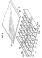
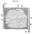
- FIG. 19 shows a condenser comprising flat refrigerant tubes embodying the invention.
- the condenser comprises a pair of headers 61, 62 arranged at left and right in parallel and spaced apart from each other, parallel flat refrigerant tubes 63 each joined at its opposite ends to the two headers 61, 62, corrugated fins 64 arranged in air flow clearances between the adjacent refrigerant tubes 63 and brazed to the adjacent refrigerant tubes 63, an inlet pipe 65 connected to the upper end of the left header 61, an outlet pipe 66 connected to the lower end of the right 62, a left partition 67 provided inside the left header 61 and positioned above the midportion thereof, and a right partition 68 provided inside the right header 62 and positioned below the midportion thereof, the number of refrigerant tubes 63 between the inlet pipe 65 and the left partition 67, the number of refrigerant tubes 63 between the left partition 67 and the right partition 68 and the number of regrigerant tubes
- the refrigerant tubes 63 for use in the above condenser are concerned with the present invention.
- Refrgigerant tubes embodying the invention will be described below.
- the following embodiments are all 10 to 40% in opening ratio which is the proportion of all communication holes in each reinforcing wall to the reinforcing wall.
- the communication holes formed in a plurality of reinforcing walls are all in a staggered arrangement.
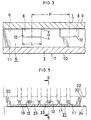
- a refrigerant tube T1 for heat exchangers is formed by a flat aluminum tube 7 having parallel refrigerant passages 6 in its interior and comprising flat upper and lower walls 1, 2, left and right vertical side walls 3, 4 connected respectively between the left side edges of the upper and lower walls 1, 2 and between the right side edges thereof, and a plurality of reinforcing walls 5 connected between the upper and lower walls 1, 2, extending longitudinally of the tube and spaced apart from one another by a predetermined distance.
- the reinforcing walls 5 are each formed with a plurality of rectangular communiction holes 8 for causing the parallel refrigerant passages 6 to communicate with each other therethrough,
- the flat aluminum tube 7 is prepared from upper and lower two aluminum sheets 9, 10 by vertically bending the lower sheet 10 at its opposite side edges, joining the bent side edges to the respective side edges of the upper aluminum sheet 9 so as to define a hollow portion by the two aluminum sheets 9, 10.
- the reinforcing walls 5 are formed by parallel ridges 11 projecting inward from the lower wall 2 and joined to the inner surface of the upper wall 1.
- the rectangular communication holes 8 are formed by rectangular cutouts 12 provided in the upper edge of each ridge 11 at a predetermined spacing and having their openings closed by the upper wall 1.
- the refrigerant tube T1 is produced by the following method.
- an aluminum sheet blank in the form of a brazing sheet covered with a brazing filler metal over the lower surface and having a thickness greater than that of upper and lower walls of the refrigerant tube to be produced is first rolled by a pair of upper and lower rolls 13, 17.
- the upper roll 13 has parallel annular grooves 14 arranged at a spacing, first small-diameter portions 15 formed at the respective outer sides of the arrangement of grooves 14 and each having a periphery of the same diameter as the bottom faces of the grooves 14, and second small-diameter portions 16 positioned externally of the respective first small-diameter portions 15 and having a smaller diameter and a greater width than the portions 15.
- the lower roll 17 is provided, at its respective outer ends, with large-diameter portions 18 each having an outer end face flush with that of the second small-diameter portion 16 and having a smaller width than the portion 16.
- the peripheral surfaces of the rolling rolls 13, 17 form a flat portion 19 providing the lower wall 2 by thinning the sheet blank to a specified thickness.
- the rolls 13, 17 also form ridges 11 projecting from the flat portion 19 integrally therewith by means of the annular grooves 14.
- Further formed at the respective side edges of the flat portion 19 are upright portions 20 each including an inner stepped part 20a with the same height as the ridges 11, and a thin wall 20b extending upward from the outer edge of the stepped part 20a.
- the rolled aluminum sheet 21 is then passed between a pair of upper and lower rolls 22, 24.
- the upper roll 22 has rectangular protrusions 23 arranged at a predetermined spacing at a position corresponding to each of the parallel annular grooves 14 in the upper roll 13 for the preceding step.
- This rolling operation forms rectangular cutouts 12 in the upper edges of the respective ridges 11 at the predetermined spacing, whereby the lower aluminum sheet 10 is obtained.
- the multiplicity of protrusions 23 are in a staggered arrangement so that the cutouts 12 are formed in the upper edges of the parallel ridges 11 in a staggered arrangement when seen from above.
- the above method of producing the lower aluminum sheet 10 requires two steps for forming the ridges 11 having the cutouts 12. As shown in FIG. 7, however, these ridges 11 with the cutouts 12 can be formed by a single step by using in combination with the lower roller 17 of the first step an upper roll 26 which is formed in each of parallel annular grooves 14 with protrusions 25 arranged at a predetermined spacing and having a height smaller than the depth of the grooves.
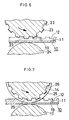
- the flat upper aluminum sheet 9 is prepared which comprises a brazing sheet having opposite surfaces each covered with a brazing filler metal layer.
- the upper aluminum sheet 9 has at each of its opposite side edge portions an upper surface in the form of a slope 27 slanting outwardly downward.
- each side edge portion of the upper aluminum sheet 9 is placed on the stepped part 20a of the upright portion 20 of the lower aluminum sheet 10, and the thin wall 20b (indicated in a broken line) is crimped onto the slope 27 of the upper aluminum sheet 9.
- the lower surface of the upper sheet 9 is brazed to the stepped parts 20a of the upright portions 20 of the lower sheet 10 and to the top ends of the ridges 11 thereof, whereby the refrigerant tube T1 is fabricated.
- the peripheral surface of the upper rolling roll 13 may be formed with indentations and projections which are triangular wavelike in cross section, or knurled.
- the lower aluminum sheet 10 then obtained has projections and indentations extending longitudinally thereof over the entire inner surface, or has an inner surface formed with latticelike projections or indentations. This gives an increased surface area to the lower wall 2.
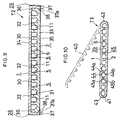
- FIG. 9 shows this embodiment, i.e., a refrigerant tube T2 for use in heat exchangers.
- the tube T2 has the same construction as Embodiment 1 except that the tube T2 has left and right side walls 28, 29 of double structure, communication holes 30 in the form of an inverted trapezoid, and a plurality of relatively low upward projections 31 integral with the lower wall 2, extending longitudinally thereof and spaced apart from one another for giving a heat transfer surface of increased area.
- the holes 30 can be provided by forming trapezoidal cutouts 32 in the upper edges of the ridges 11.
- the tube T2 comprises a flat aluminum tube 33, which is prepared by bending opposite side edges of upper and lower two aluminum sheets 34, 35, fitting the bent side edges of one of the two aluminum sheets 34, 35 respectively over the bent side edges of the other aluminum sheet and joining the fitted portions so as to define a hollow portion by the sheets 34, 35.
- the side walls 28, 29 are formed by the following method.
- Upright portions 36 having the same height as the reinforcing walls 5 are provided respectively at opposite sides of the lower aluminum sheet 35, and a slope 38 slanting outwardly upward is formed at the bottom edge of each upright portion 36.
- a depending portion 37 is formed at each of opposite sides of the upper aluminum sheet 34, the portion 37 being in contact with with the outer side face of the upright portion 36 and projecting downward slightly beyond the lower surface of the lower wall 2.
- the downward projections 37a of the depending portions 37 are crimped onto the respective slopes 38 of the lower aluminum sheet 35, and the portions where the upper and lower aluminum sheets 34, 35 are in contact with each other are brazed.
- FIG. 10 shows this embodiment, i.e., a refrigerant tube T3 for use in heat exchangers, which comprises a flat aluminum tube 39.
- the tube 39 is prepared from an aluminum sheet 40 in the form of a brazing sheet having a brazing filler metal layer on one surface thereof, by folding the sheet at the midportion of its width like a hairpin with the brazing layer out so as to form a hollow portion, bending opposite side edges to an arcuate shape and joining the side edges in butting contact with each other.
- the tube 39 therefore has circular-arc left and right side walls 41, 42.
- the butt joint 43 thus made is oblique in cross section so as to form the joint 43 over an increased area.
- Each of reinforcing walls 44 is formed by joining a downward ridge 44a inwardly projecting from the upper wall 1 to an upward ridge 44b inwardly projecting from the lower wall 2.
- Each of trapezoidal communication holes 5 is formed by the combination of a pair of trapezoidal cutouts 45a, 45b. Such cutouts 45a, 45b are formed respectively in the lower edge of the downward ridge 44a and the upper edge of the upward ridge 44b at a predetermined spacing.
- FIG. 11 shows this embodiment, i.e., a heat exchange refrigerant tube T4, which has two kinds of reinforcing walls 46.
- the walls 46 of one kind are each formed by a downward ridge 46a inwardly projecting from an upper wall 1 and joined to a flat inner surface of a lower wall 2.
- the walls 46 of the other kind are each formed by an upward ridge 46b inwardly projecting from the lower wall 2 and joined to a flat inner surface of the upper wall 1.
- the two kinds of walls 46 are arranged alternately.
- Trapezoidal communication holes 47 are formed by trapezoidal cutouts 47a, 47b provided respectively in the lower edge of the downward ridge 46a and in the upper edge of the upward ridge 46b and have their openings closed by one of the upper and lower walls 1, 2.
- the present embodiment is the same as Embodiment 3.
- FIG. 12 shows this embodiment, i.e., a heat exchanger refrigerant tube T5.
- the tube T5 has reinforcing walls 48 which are formed by downward ridges 48a inwardly projecting from an upper wall 1 and joined to a flat inner surface of a lower wall 2.
- Trapezoidal communication holes 49 are formed by providing trapezoidal cutouts 49a in the lower edges of the ridges 48a at a predetermined spacing and closing the openings of the cutouts 49a with the lower wall 2.
- the present embodiment is the same as Embodiment 3 except for this feature.
- FIG. 13 shows this embodiment, i.e., a heat exchange refrigerant tube T4, which comprises a flat aluminum tube 50.
- the tube 50 is prepared from upper and lower two aluminum sheets 51, 53 by bending opposite side edges of the sheets to an arcuate shape toward each other so as to form a hollow portion, butting the sheets against each other edge to edge and joining the butted edges.
- the present embodiment is the same as Embodiment 3.
- the left and right butt joints 53, 54 are oblique in cross section as is the case with Embodiment 3.
- the aluminum sheet having the ridges, etc. and used in the foregoing embodiments can be replaced by an aluminum extrudate of specified cross section.
- a refrigerant tube which is 508 mm in length, 16.5 mm in the distance between side walls 3, 4, 1 mm in the height between upper and lower walls 1, 2, six in the number of reinforcing walls 5, 2.4 mm in the pitch of reinforcing walls 5, 0.3 mm in the thickness of reinforcing walls 5, 1.6 mm in the pitch P of communication holes 8, 0.8 mm in the length L of communication holes 8, 0.2 mm in the height H of communication holes 8, and 10% in opening ratio.
- Example 2 The same refrigerant tube as that of Example 1 except that the tube is 0.6 mm in the height of communication holes and 30% in opening ratio.
- Example 2 The same refrigerant tube as that of Example 1 except that the tube is 0.8 mm in the height of communication holes and 40% in opening ratio.
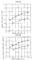
- the refrigerant tubes of Example 1 and Comparative Example were used to determine the relationship between the average quality X of refrigerant (the fraction of vapor mass in refrigerant) and the thermal conductance hA (h: heat transfer coefficient, A: the area of heat transfer surface inside the refrigerant tube).
- the method of determination was as follows. The refrigerant tube was placed in a cooling water channel, a refrigerant comprising HFC134a was passed through the tube, and cooling water was passed through the channel.
- the mass velocity G of the refrigerant was set at 400 kg/m 2 ⁇ s, the refrigerant inlet temperature at 65° C, and the heat flux between the refrigerant and the cooling water at 8 kW/m 2 .
- the flow rate of the cooling water was so set as to give a Reynolds number of 1500.
- the thermal conductance hA was measured at varying values of average quality X.
- Example 2 The refrigerant tubes of Example 2 and Comparative Example were used to determine the relationship between the average quality X of refrigerant and the heat transfer coefficient h by the same method as in Evaluation Test 1.
- FIG. 15 shows the result.
- FIG. 15 reveals that at any value of average quality X, the heat transfer coefficient h is greater when the reinforcing walls are formed with communication holes than when no holes are formed.
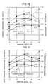
- the refrigerant tubes of Examples 1 to 4 and Comparative Example were used to determine the relationship between the opening ratio and the thermal conductance hA at an average quality X of refrigerant of 20%, 50% or 80%, and the relationship between the opening ratio and the coefficient of friction f when the average quality X of refrigerant was 50% (Reynolds number of refrigerant: 10 4 ), the relationships being determined by the same method as in Evaluation Test 1.
- FIG. 16 shows the result.
- FIG. 16 indicates that at any value of average quality X, the thermal conductance hA is greater when the reinforcing walls are formed with communication holes than when no holes are formed, and that the thermal conductance hA is especially great at an opening ratio of 20%.
- the refrigerant tubes of Examples 1 to 4 and Comparative Example were used to determine, by the same method as in Evaluation Test 1, the relationship between the opening ratio and the heat transfer coefficient h at an average quality X of refrigrant of 20%, 50% or 80%, and the relationship between the opening ratio and the coefficient of friction f when the average quality X of refrigerant was 50% (Reynolds number: 10 4 ).
- FIG. 17 shows the result.
- FIG. 17 indicates that at any value of average quality X, the heat transfer coefficient h is greater when the reinforcing walls are formed with communication holes than when no holes are formed, and that the heat transfer coefficient h is especially great at an opening ratio of 20%.
- FIG. 19 Three kinds of condensers of the multiflow type shown in FIG. 19 were fabricated using the refrigerant tube of Example 2 or Comparative Example. More specifically, 37 refrigerant tubes, and corrugated fins, 22 mm in width, 7 mm in height and 1 mm in fin pitch, were used for making a core portion measuring 326 mm in width, 330.5 mm in height and 0.108 m 2 in front area, and opposite ends of each tube were connected to right and left headers. No partition was provided in opposite headers in the condenser of the type I (single pass).
- the condenser of the type II had a partition inside the left header above the midportion thereof, another partition inside the right header below the midportion thereof, 20 refrigerant tubes positioned above the partition of the left header, 11 refrigerant tubes arranged between the two partitions, and 6 refrigerant tubes positioned below the partition of the tight header (three passes).
- the condenser of the type III had two partitions positioned respectively in an upper portion and a lower portion of the left header, two partitions positioned inside the right header, one at an intermediate level between the two partitions of the left header and the other at a level below the lower partition of the left header, 12 refrigerant tubes positioned above the upper partition of the left header, 9 refirgerant tubes between the upper partition of the left header and the upper partition of the right header, 7 refrigerant tubes positioned between the upper partition of the right header and the lower partition of the left header, 5 refrigerant tubes positioned between the lower partition of the left header and the lower partition of the right header, and 4 refrigerant tubes positioned below the lower partition of the right header (five passes).
- the condensers were checked for the relationship between the refrigerant pressure loss ⁇ Pr and the quantity of heat radiated per unit front area, Q/Fa.
- FIG. 18 shows the result.
- FIG. 18 shows that the capacitor comprising the refrigerant tube wherein the reinforcing walls are formed with communication holes at an opening ratio of 20% exhibits an improved performance over the condenser comprising the refrigerant tube having no communication holes in the reinforcing walls and achieves an improvement even when the pressure loss is the same.
Landscapes
- Engineering & Computer Science (AREA)
- Mechanical Engineering (AREA)
- Physics & Mathematics (AREA)
- Thermal Sciences (AREA)
- General Engineering & Computer Science (AREA)
- Heat-Exchange Devices With Radiators And Conduit Assemblies (AREA)
- Details Of Heat-Exchange And Heat-Transfer (AREA)
Description
Claims (6)
- Heat exchanger refrigerant tube comprising a flat aluminum tube (7) having parallel refrigerant passages (6) and comprising upper and lower walls and a plurality of reinforcing walls (5) connected between the upper and lower walls, the reinforcing walls (5) extending longitudinally of the tube and spaced apart from one another by a predetermined distance, the flat aluminum tube being formed by joining upper and lower aluminum sheets so as to define a hollow portion by the two aluminum sheets, the reinforcing walls (5) being formed by a ridge projecting inward from one of the upper and lower walls integrally therewith and joined to a flat inner surface of the other wall, the reinforcing walls (5) being each formed with a plurality of communication holes for causing the parallel refrigerant passages (6) to communicate with one another therethrough, the communication holes are formed by cutouts formed in an edge of the ridge at a predetermined spacing and having their openings closed by the other wall, each of the reinforcing walls (5) being 10 to 40% in opening ratio which is the proportion of the area of all the communication holes in the reinforcing wall (5) to the surface area of the reinforcing wall.
- Heat exchanger refrigerant tube as defined in claim 1, wherein the opening ratio is 10 to 30%.
- Heat exchanger refrigerant tube as defined in claim 1, wherein the opening ratio is about 20%.
- Heat exchanger refrigerant tube as defined in claim 1, 2 or 3, wherein the communication holes are rectangular or trapezoidal in shape.
- Heat exchanger refrigerant tube as defined in claim 1, 2 or 3, wherein the communication holes formed in the plurality of reinforcing walls are in a staggered arrangement relative to an adjacent reinforcing wall.
- Heat exchanger refrigerant tube as defined in claim 1, wherein the aluminum sheet comprises a brazing sheet having a brazing filler metal layer over at least one of opposite surfaces thereof.
Applications Claiming Priority (3)
| Application Number | Priority Date | Filing Date | Title |
|---|---|---|---|
| JP7172007A JPH0926278A (en) | 1995-07-07 | 1995-07-07 | Heat exchanger refrigerant flow pipe and car air-conditioner condenser |
| JP172007/95 | 1995-07-07 | ||
| JP17200795 | 1995-07-07 |
Publications (2)
| Publication Number | Publication Date |
|---|---|
| EP0762070A1 EP0762070A1 (en) | 1997-03-12 |
| EP0762070B1 true EP0762070B1 (en) | 2001-02-28 |
Family
ID=15933798
Family Applications (1)
| Application Number | Title | Priority Date | Filing Date |
|---|---|---|---|
| EP96110844A Expired - Lifetime EP0762070B1 (en) | 1995-07-07 | 1996-07-04 | Refrigerant tubes for heat exchangers |
Country Status (17)
| Country | Link |
|---|---|
| EP (1) | EP0762070B1 (en) |
| JP (1) | JPH0926278A (en) |
| KR (1) | KR100414852B1 (en) |
| CN (1) | CN1111717C (en) |
| AR (1) | AR002691A1 (en) |
| AT (1) | ATE199456T1 (en) |
| AU (1) | AU711980B2 (en) |
| BR (1) | BR9602985A (en) |
| CA (1) | CA2180598C (en) |
| CZ (1) | CZ293383B6 (en) |
| DE (1) | DE69611868T2 (en) |
| ES (1) | ES2154366T3 (en) |
| IN (1) | IN188905B (en) |
| MX (1) | MX9602646A (en) |
| MY (1) | MY119070A (en) |
| TW (1) | TW296425B (en) |
| ZA (1) | ZA965732B (en) |
Families Citing this family (15)
| Publication number | Priority date | Publication date | Assignee | Title |
|---|---|---|---|---|
| KR100497847B1 (en) * | 1996-10-24 | 2005-09-30 | 쇼와 덴코 가부시키가이샤 | Evaporator |
| DE10201511A1 (en) * | 2002-01-17 | 2003-07-31 | Behr Gmbh & Co | Welded multi-chamber tube |
| WO2004015350A1 (en) * | 2002-08-09 | 2004-02-19 | Showa Denko K.K. | Flat tube and process for producing heat exchanger with use of the flat tube |
| WO2008064263A2 (en) | 2006-11-22 | 2008-05-29 | Johnson Controls Technology Company | Multi-block circuit multichannel heat exchanger |
| TWI468535B (en) * | 2012-11-20 | 2015-01-11 | Truan Sheng Lui | Method for inhibiting the diffusion of silicon by means of coarse aluminum crystals |
| JP6243232B2 (en) * | 2014-01-17 | 2017-12-06 | 株式会社ティラド | Method of manufacturing fin for heat exchanger, fin and heat exchanger |
| CN103968700B (en) * | 2014-05-26 | 2016-08-24 | 赵耀华 | A kind of high efficient heat exchanging water pipe and heat pipe radiant heating/refrigeration system |
| CN108253827B (en) * | 2016-12-28 | 2020-06-23 | 神讯电脑(昆山)有限公司 | Aluminum extrusion type hot plate and manufacturing method thereof |
| CN109097074B (en) * | 2018-10-15 | 2023-09-19 | 中冶焦耐(大连)工程技术有限公司 | Single-channel water supply bottom water-cooling coke quenching car and working method thereof |
| CN109357545B (en) * | 2018-11-28 | 2024-05-31 | 博格华纳排放系统(宁波)有限公司 | Cooler for vehicle |
| CN110670799B (en) * | 2019-10-10 | 2021-11-09 | 李居强 | Structural plate with cavity and manufacturing method thereof |
| CN111192221B (en) * | 2020-01-07 | 2024-04-16 | 中南大学 | Aluminum electrolysis fire hole image repairing method based on deep convolution generation countermeasure network |
| US11255610B2 (en) * | 2020-01-22 | 2022-02-22 | Cooler Master Co., Ltd. | Pulse loop heat exchanger and manufacturing method of the same |
| JP7532788B2 (en) * | 2020-02-05 | 2024-08-14 | 株式会社レゾナック | Battery Module |
| WO2022145003A1 (en) * | 2020-12-28 | 2022-07-07 | 三菱電機株式会社 | Dehumidifying device |
Family Cites Families (7)
| Publication number | Priority date | Publication date | Assignee | Title |
|---|---|---|---|---|
| US3528496A (en) * | 1967-11-03 | 1970-09-15 | Union Carbide Corp | Plate-fin heat exchanger |
| DE2209325C3 (en) * | 1970-05-18 | 1978-08-03 | Noranda Metal Industries Inc., Bellingham, Wash. (V.St.A.) | Heat exchange tube |
| DE3731669A1 (en) * | 1987-09-21 | 1989-04-06 | Sueddeutsche Kuehler Behr | Flat heat exchanger tube |
| DE68912636D1 (en) * | 1988-04-13 | 1994-03-10 | Mitsubishi Aluminium | Heat exchanger core. |
| JP2718193B2 (en) * | 1989-07-08 | 1998-02-25 | 株式会社デンソー | Heat exchanger |
| JP3364665B2 (en) * | 1993-03-26 | 2003-01-08 | 昭和電工株式会社 | Refrigerant flow pipe for heat exchanger |
| US5323851A (en) * | 1993-04-21 | 1994-06-28 | Wynn's Climate Systems, Inc. | Parallel flow condenser with perforated webs |
-
1995
- 1995-07-07 JP JP7172007A patent/JPH0926278A/en active Pending
-
1996
- 1996-07-02 IN IN1218CA1996 patent/IN188905B/en unknown
- 1996-07-02 MY MYPI96002708A patent/MY119070A/en unknown
- 1996-07-03 AU AU58344/96A patent/AU711980B2/en not_active Ceased
- 1996-07-04 DE DE69611868T patent/DE69611868T2/en not_active Expired - Fee Related
- 1996-07-04 EP EP96110844A patent/EP0762070B1/en not_active Expired - Lifetime
- 1996-07-04 AT AT96110844T patent/ATE199456T1/en not_active IP Right Cessation
- 1996-07-04 ES ES96110844T patent/ES2154366T3/en not_active Expired - Lifetime
- 1996-07-04 CZ CZ19962008A patent/CZ293383B6/en not_active IP Right Cessation
- 1996-07-05 MX MX9602646A patent/MX9602646A/en not_active IP Right Cessation
- 1996-07-05 TW TW085108124A patent/TW296425B/zh active
- 1996-07-05 ZA ZA965732A patent/ZA965732B/en unknown
- 1996-07-05 BR BR9602985A patent/BR9602985A/en not_active IP Right Cessation
- 1996-07-05 CA CA002180598A patent/CA2180598C/en not_active Expired - Fee Related
- 1996-07-05 AR ARP960103459A patent/AR002691A1/en unknown
- 1996-07-05 CN CN96108774A patent/CN1111717C/en not_active Expired - Fee Related
- 1996-07-06 KR KR1019960027365A patent/KR100414852B1/en not_active IP Right Cessation
Also Published As
| Publication number | Publication date |
|---|---|
| KR100414852B1 (en) | 2004-03-31 |
| AU711980B2 (en) | 1999-10-28 |
| DE69611868T2 (en) | 2001-06-13 |
| IN188905B (en) | 2002-11-16 |
| CN1111717C (en) | 2003-06-18 |
| EP0762070A1 (en) | 1997-03-12 |
| CA2180598C (en) | 2007-06-05 |
| TW296425B (en) | 1997-01-21 |
| AU5834496A (en) | 1997-01-23 |
| JPH0926278A (en) | 1997-01-28 |
| CZ293383B6 (en) | 2004-04-14 |
| CN1140828A (en) | 1997-01-22 |
| MX9602646A (en) | 1997-06-28 |
| AR002691A1 (en) | 1998-03-25 |
| ES2154366T3 (en) | 2001-04-01 |
| DE69611868D1 (en) | 2001-04-05 |
| KR970007278A (en) | 1997-02-21 |
| ATE199456T1 (en) | 2001-03-15 |
| ZA965732B (en) | 1997-01-23 |
| CA2180598A1 (en) | 1997-01-08 |
| MY119070A (en) | 2005-03-31 |
| BR9602985A (en) | 1998-04-28 |
| CZ9602008A3 (en) | 1997-04-16 |
Similar Documents
| Publication | Publication Date | Title |
|---|---|---|
| EP0617250B1 (en) | A method of producing a refrigerant tube for heat exchangers | |
| US5931226A (en) | Refrigerant tubes for heat exchangers | |
| EP0881449A2 (en) | Refrigerant tubes for heat exchangers | |
| EP0762070B1 (en) | Refrigerant tubes for heat exchangers | |
| US7749609B2 (en) | Metal plate for producing flat tube, flat tube and process for producing the flat tube | |
| EP1180403B1 (en) | Process for producing flat heat exchange tubes | |
| AU2002304254A1 (en) | Metal plate for producing flat tube, flat tube and process for producing the flat tube | |
| JP2004530092A5 (en) | ||
| JP2004530092A (en) | Heat exchanger | |
| JP2000193387A (en) | Flat heat exchange pipe and its manufacture | |
| JP2000193387A5 (en) | ||
| US20060162919A1 (en) | Flat tube and process for producing heat exchanger with use of the flat tube | |
| JP3947830B2 (en) | Manufacturing method of flat heat exchange tube | |
| EP1027942A1 (en) | Tube for heat exchanger and method of manufacturing same | |
| US5881457A (en) | Method of making refrigerant tubes for heat exchangers | |
| JP5066709B2 (en) | Manufacturing method of flat tube | |
| JP2004069258A (en) | Flat tube, and method of manufacturing heat exchanger using flat tube | |
| JPH10185358A (en) | Evaporator | |
| JP2000161896A (en) | Heat exchanger and production thereof |
Legal Events
| Date | Code | Title | Description |
|---|---|---|---|
| PUAI | Public reference made under article 153(3) epc to a published international application that has entered the european phase |
Free format text: ORIGINAL CODE: 0009012 |
|
| AK | Designated contracting states |
Kind code of ref document: A1 Designated state(s): AT CH DE ES FR GB IT LI SE |
|
| 17P | Request for examination filed |
Effective date: 19970626 |
|
| 17Q | First examination report despatched |
Effective date: 19990318 |
|
| GRAG | Despatch of communication of intention to grant |
Free format text: ORIGINAL CODE: EPIDOS AGRA |
|
| GRAG | Despatch of communication of intention to grant |
Free format text: ORIGINAL CODE: EPIDOS AGRA |
|
| GRAH | Despatch of communication of intention to grant a patent |
Free format text: ORIGINAL CODE: EPIDOS IGRA |
|
| GRAH | Despatch of communication of intention to grant a patent |
Free format text: ORIGINAL CODE: EPIDOS IGRA |
|
| GRAA | (expected) grant |
Free format text: ORIGINAL CODE: 0009210 |
|
| AK | Designated contracting states |
Kind code of ref document: B1 Designated state(s): AT CH DE ES FR GB IT LI SE |
|
| PG25 | Lapsed in a contracting state [announced via postgrant information from national office to epo] |
Ref country code: LI Free format text: LAPSE BECAUSE OF FAILURE TO SUBMIT A TRANSLATION OF THE DESCRIPTION OR TO PAY THE FEE WITHIN THE PRESCRIBED TIME-LIMIT Effective date: 20010228 Ref country code: CH Free format text: LAPSE BECAUSE OF FAILURE TO SUBMIT A TRANSLATION OF THE DESCRIPTION OR TO PAY THE FEE WITHIN THE PRESCRIBED TIME-LIMIT Effective date: 20010228 |
|
| REF | Corresponds to: |
Ref document number: 199456 Country of ref document: AT Date of ref document: 20010315 Kind code of ref document: T |
|
| REG | Reference to a national code |
Ref country code: CH Ref legal event code: EP |
|
| REG | Reference to a national code |
Ref country code: ES Ref legal event code: FG2A Ref document number: 2154366 Country of ref document: ES Kind code of ref document: T3 |
|
| REF | Corresponds to: |
Ref document number: 69611868 Country of ref document: DE Date of ref document: 20010405 |
|
| ET | Fr: translation filed | ||
| ITF | It: translation for a ep patent filed | ||
| REG | Reference to a national code |
Ref country code: GB Ref legal event code: 732E |
|
| REG | Reference to a national code |
Ref country code: CH Ref legal event code: PL |
|
| REG | Reference to a national code |
Ref country code: GB Ref legal event code: IF02 |
|
| PLBE | No opposition filed within time limit |
Free format text: ORIGINAL CODE: 0009261 |
|
| STAA | Information on the status of an ep patent application or granted ep patent |
Free format text: STATUS: NO OPPOSITION FILED WITHIN TIME LIMIT |
|
| REG | Reference to a national code |
Ref country code: FR Ref legal event code: TP |
|
| 26N | No opposition filed | ||
| PGFP | Annual fee paid to national office [announced via postgrant information from national office to epo] |
Ref country code: SE Payment date: 20030707 Year of fee payment: 8 |
|
| PGFP | Annual fee paid to national office [announced via postgrant information from national office to epo] |
Ref country code: AT Payment date: 20030711 Year of fee payment: 8 |
|
| PG25 | Lapsed in a contracting state [announced via postgrant information from national office to epo] |
Ref country code: AT Free format text: LAPSE BECAUSE OF NON-PAYMENT OF DUE FEES Effective date: 20040704 |
|
| PG25 | Lapsed in a contracting state [announced via postgrant information from national office to epo] |
Ref country code: SE Free format text: LAPSE BECAUSE OF NON-PAYMENT OF DUE FEES Effective date: 20040705 |
|
| EUG | Se: european patent has lapsed | ||
| PGFP | Annual fee paid to national office [announced via postgrant information from national office to epo] |
Ref country code: FR Payment date: 20060719 Year of fee payment: 11 |
|
| PGFP | Annual fee paid to national office [announced via postgrant information from national office to epo] |
Ref country code: ES Payment date: 20060724 Year of fee payment: 11 |
|
| PGFP | Annual fee paid to national office [announced via postgrant information from national office to epo] |
Ref country code: IT Payment date: 20060731 Year of fee payment: 11 |
|
| PGFP | Annual fee paid to national office [announced via postgrant information from national office to epo] |
Ref country code: DE Payment date: 20070628 Year of fee payment: 12 |
|
| PGFP | Annual fee paid to national office [announced via postgrant information from national office to epo] |
Ref country code: GB Payment date: 20070704 Year of fee payment: 12 |
|
| REG | Reference to a national code |
Ref country code: FR Ref legal event code: ST Effective date: 20080331 |
|
| PG25 | Lapsed in a contracting state [announced via postgrant information from national office to epo] |
Ref country code: FR Free format text: LAPSE BECAUSE OF NON-PAYMENT OF DUE FEES Effective date: 20070731 |
|
| REG | Reference to a national code |
Ref country code: ES Ref legal event code: FD2A Effective date: 20070705 |
|
| PG25 | Lapsed in a contracting state [announced via postgrant information from national office to epo] |
Ref country code: ES Free format text: LAPSE BECAUSE OF NON-PAYMENT OF DUE FEES Effective date: 20070705 |
|
| GBPC | Gb: european patent ceased through non-payment of renewal fee |
Effective date: 20080704 |
|
| PG25 | Lapsed in a contracting state [announced via postgrant information from national office to epo] |
Ref country code: DE Free format text: LAPSE BECAUSE OF NON-PAYMENT OF DUE FEES Effective date: 20090203 |
|
| PG25 | Lapsed in a contracting state [announced via postgrant information from national office to epo] |
Ref country code: GB Free format text: LAPSE BECAUSE OF NON-PAYMENT OF DUE FEES Effective date: 20080704 |
|
| PG25 | Lapsed in a contracting state [announced via postgrant information from national office to epo] |
Ref country code: IT Free format text: LAPSE BECAUSE OF NON-PAYMENT OF DUE FEES Effective date: 20070704 |