EP0837666B1 - Ambulante wirbelsäulenstreckvorrichtung - Google Patents
Ambulante wirbelsäulenstreckvorrichtung Download PDFInfo
- Publication number
- EP0837666B1 EP0837666B1 EP96923263A EP96923263A EP0837666B1 EP 0837666 B1 EP0837666 B1 EP 0837666B1 EP 96923263 A EP96923263 A EP 96923263A EP 96923263 A EP96923263 A EP 96923263A EP 0837666 B1 EP0837666 B1 EP 0837666B1
- Authority
- EP
- European Patent Office
- Prior art keywords
- support members
- spine
- region
- support member
- vertical
- Prior art date
- Legal status (The legal status is an assumption and is not a legal conclusion. Google has not performed a legal analysis and makes no representation as to the accuracy of the status listed.)
- Expired - Lifetime
Links
Images


Classifications
-
- A—HUMAN NECESSITIES
- A61—MEDICAL OR VETERINARY SCIENCE; HYGIENE
- A61F—FILTERS IMPLANTABLE INTO BLOOD VESSELS; PROSTHESES; DEVICES PROVIDING PATENCY TO, OR PREVENTING COLLAPSING OF, TUBULAR STRUCTURES OF THE BODY, e.g. STENTS; ORTHOPAEDIC, NURSING OR CONTRACEPTIVE DEVICES; FOMENTATION; TREATMENT OR PROTECTION OF EYES OR EARS; BANDAGES, DRESSINGS OR ABSORBENT PADS; FIRST-AID KITS
- A61F5/00—Orthopaedic methods or devices for non-surgical treatment of bones or joints; Nursing devices; Anti-rape devices
- A61F5/01—Orthopaedic devices, e.g. splints, casts or braces
- A61F5/0102—Orthopaedic devices, e.g. splints, casts or braces specially adapted for correcting deformities of the limbs or for supporting them; Ortheses, e.g. with articulations
- A61F5/012—Orthopaedic devices, e.g. splints, casts or braces specially adapted for correcting deformities of the limbs or for supporting them; Ortheses, e.g. with articulations inflatable
-
- A—HUMAN NECESSITIES
- A61—MEDICAL OR VETERINARY SCIENCE; HYGIENE
- A61F—FILTERS IMPLANTABLE INTO BLOOD VESSELS; PROSTHESES; DEVICES PROVIDING PATENCY TO, OR PREVENTING COLLAPSING OF, TUBULAR STRUCTURES OF THE BODY, e.g. STENTS; ORTHOPAEDIC, NURSING OR CONTRACEPTIVE DEVICES; FOMENTATION; TREATMENT OR PROTECTION OF EYES OR EARS; BANDAGES, DRESSINGS OR ABSORBENT PADS; FIRST-AID KITS
- A61F5/00—Orthopaedic methods or devices for non-surgical treatment of bones or joints; Nursing devices; Anti-rape devices
- A61F5/01—Orthopaedic devices, e.g. splints, casts or braces
- A61F5/02—Orthopaedic corsets
- A61F5/024—Orthopaedic corsets having pressure pads connected in a frame for reduction or correction of the curvature of the spine
Definitions
- This invention relates in general to devices to aid in the healing of spinal injuries or to support various spinal regions to prevent the occurrence or re-occurrence of injuries.
- the human spinal column is a major component of the skeletal system of thirty-three bones comprising seven cervical, twelve thoracic, and five lumbar vertebrae, with the latter merging endwardly into the five fused sacral and the four fused coccyx vertebrae.
- the twenty-four individual vertebrae have various bony projections with one projection, directed outward from the back of the spine, known as the spinous process. This spinous process of each vertebra can be felt along the back as hard knobs.
- the individual vertebrae are connected and supported by various cartilages, muscles and ligaments which allow flexibility for banding and twisting of the torso.
- each vertebra is an intervertebral disc which functions to cushion and separate each vertebra, helping to prevent compression of the peripheral spinal nerves branching off from the spinal cord and housed within the spinal column.
- the interior structure of the disk can rupture leading to a displacement of the intra-disk cushioning fluid and a resulting bulging of the outer disk surface.
- This bulging of the disk surface can impinge on nerve structures proximal to the disk area causing inflammation and further aggravation of the neurological anatomy involved.
- Such neurological involvement is invariably accompanied by pain, loss of strength in the lower extremities, or worse.
- the outer surface of the disk can rupture completely leading to an extrusion of the viscous intra-disk fluid, a condition which generally requires invasive therapy.
- Displacement of one or more of the individual vertebrae from its normal position can also create pressure against the spinal nerves, most often resulting in pain, frequently severe in intensity. Such displacement is often the result of unequal tension of the musdes supporting the spinal column, causing one or more of the individual vertebrae to be pulled out of alignment with the rest. This unequal tension of the muscles can be caused from a variety of factors, not all of which are physical. These include over-exertion, uneven muscular stress, emotional tension and direct physical trauma.
- a significant proportion of back pain experienced by the general public occurs in the lower portion of the back generally referred to as the lumbar region, or spinal segments L-5 through L-1, specifically.
- the pressure exerted against the nerves can be alleviated by re-aligning the affected vertebrae of this region, resulting in reduction or elimination of pain.
- a significant proportion of spinal injuries affecting the cervical region, or spinal segments C-1 through C-7 can also be alleviated through realignment of the affected vertebrae.
- traction procedures generally referred to as traction, which procedures shall be discussed at greater length below, in relation to the practice of the present invention. Additionally, for those injuries to the lumbar region arising from disk involvement, traction has also been demonstrated to be therapeutically effective in promoting healing of the affected anatomy, with accompanying reduction in symptoms.
- back injuries are a very costly health problem for industry, as measured in terms of lost productivity.
- the lumbar spine can be injured in essentially two ways - namely, excessive compression or excessive torsion. If the former occurs, the most common result is a damaged vertebral end plate. The preferable remedy for such injury is rest, or a near-complete avoidance of any physical activity likely to place stress on the spinal column. Corrective surgery is rarely required, as is typical of the vast majority of day-to-day back injuries.
- the human spine is the essential load bearing component in the human skeleton, an injury to any region of the spine almost inevitably causes at least some discomfort, immobility and/or pain. After an injury to the spine has occurred, it is critical that the spine be given an opportunity to heal itself. Spinal motion in the direction of the injury must be avoided if the injury is not to be aggravated, and given an opportunity to heal. It such opportunity is not provided, an injury may never heal or become severely aggravated, causing increasing discomfort and incapacitation to the affected individual.
- the spine is in constant everyday use, it is continuously subjected to stresses which may interfere with the healing process. In many instances, short of a significant period of absolute bed rest, or even more drastic, non-surgical measures such as epidural injections of anti-inflammatory agents into the spinal region, a spinal injury may never heat properly.
- braces or wraps have also been designed specifically to reinforce proper lifting techniques.
- the legs When lifting heavy objects, it is preferable to use the legs as much as possible to perform the lift, thus relieving strain from the spine and muscles of the back.
- the lift should begin with the lifter in a squatting position with the back aligned within 45° of vertical.
- individuals often lift items with the back aligned 45-90° beyond vertical such that the back bears most of the load during lifting.
- Many braces incorporate features which make it uncomfortable for a wearer to bend their back more than 45 degrees from vertical, thereby mechanically constraining the wearer from exceeding a degree of alignment of the back associated with proper lifting technique.
- Patent Number 4,768,499 to Kemp discloses a lifting belt with an unpadded lumbar panel, also designed to provide additional support to the abdominal region of the wearer during lifting; and U.S. Patent No. 5,060,639 to Marcus which also discloses a back support providing additional support to the abdominal region of the wearer, including an embodiment suited for use by expectant mothers in the latter stages of pregnancy.
- braces and belts which utilize a lumbar pad comprising fluid-filled compartments designed to conform to the unique contours of the wearer's back.
- U.S. Pat. No. 4,622,957 which issued Nov. 18,1986 to James D. Curlee, discloses a therapeutic corset adapted for the sacrum, lumbar and thoracic regions of the body.
- the corset includes a padded bladder provided with a duct for introducing fluid.
- the inflated bladder is disposed next to the user for the purpose of "filling" the unique contours of the sacro-lumbar region of the spine by providing a pressure for comfort to specific areas while controlling the overall stability of the thoracic spinal region.
- braces and belts of various designs are used to support the lumbar region of the spine after it has been injured.
- An example of such a device is disclosed in U.S. Patent Number 4,691,696 to Farfan de los Godos which comprises a belt with one or more bracing structures designed to prevent torsional rotation of the wearer's back in the direction of an existing injury, thereby relieving stress from the injured area and providing an opportunity for the injury to heal.
- Additional support braces exist in the prior art, such as that disclosed in U.S. Patent Number 5,062,414 to Grim which utilize one or more fluid-filled chambers in the lumbar region of the belt, optionally in conjunction with electrically heated resistive elements designed to warm the injured area.
- Another example of a brace comprising fluid-filled bladders in a lumbar pad, along with electrically heated resistive elements, is disclosed in U.S Patent Number 4,702, 235 to Hong.
- the Sports Plus II Belt as shown in the AliMed catalog of 1995, on page S108, utilizes a plurality of vertically-oriented air-filled chambers that are distributed within the belt and extend beyond the lumbar region alone.
- the Sports Plus II Belt has no horizontally-disposed support members capable of transmitting vertical-directed forces for relieving gravitational stresses on the lumbar region of the spine or creating a traction-like effect.
- braces of the wrap-around corset type there are several well known braces of the wrap-around corset type. Such corset braces wrap around the trunk of the body in the region of the lumbar spine. Such braces, however, are intended to reduce the compressive stress in the lumbar spine or to totally immobilize it. They are thus of limited value in the treatment of torsional or twisting injuries. In addition, they may be uncomfortable and difficult to fit to larger persons. Moreover, the highly constraining corset design imparts almost complete immobility to the torso of the wearer and is, therefore, ill-suited for use while pursuing day-to-day activities. Rigidly reinforced or rigid frame back braces are also well known. Such braces, however, also completely immobilize the entire spine. A patient using such a brace is rendered essentially disabled because he cannot move his spine in any way.
- braces and other such devices which are designed to provide active therapeutic benefit and to promote healing of the injured area.
- these devices can range from full scale clinical appliances in the form of tables, chairs or other like structures, to belts and slings designed to be used in conjunction with large appliances.
- these devices function by suspending the weight of the affected patient in a manner that almost totally removes all gravitational stresses from the affected area of the spine.
- traction apparati do far more than merely constrain the movement of the affected region of the body.
- tractional therapies are part of an aggressive, non-surgical or post-surgical regimen designed to keep the spine free from torsional and compressive forces, thus allowing the injured area to heal as rapidly and effectively as possible.
- the major drawback of most tractional therapies is that, due to the complexity of the apparatus and the need for substantial intervention by an appropriately trained health care professional to assure proper therapeutic use and optimal benefit, they are suited only for use in controlled, clinical settings.
- the time that a patient spends in a normal traction device must be dedicated time during which the patient is incapable of participating in any other activities.
- U.S. Patent Number 4,991,572 to Chases discloses another type of lumbar traction harness designed in theory to use the principles of gravity traction to relieve stresses from the lumbar spinal region, permitting efficient healing of the affected area.
- the Chases device utilizes an air-inflated bladder to increase the comfort of a patient using the device for traction therapy.
- This device is basically a traction sling which is adaptable to use in a variety of conformations and patient alignments. This variety of configurations is best illustrated by reference to FIGS. 6-11 of the Chases reference.
- the principal advantage of this device is its flexibility of use, being adaptable to a number of patient orientations, unlike the majority of prior art traction table devices, whether mechanical or gravitational, such as those used in conjunction with the device of the Burton et al patent.
- the patient undergoing therapy must dedicate the time to participation in the therapy and cannot pursue any normal day-today activities, whether or not employment-related, during therapy.
- cervical traction for treating trauma to the muscles and ligaments of the neck and the cervical and upper thoracic vertebrae and associated spinal nerves.
- cervical traction By applying cervical traction, a "cervical separation" is produced which alleviates pain caused by compression on the nerves, while allowing more blood flow to the affected tissue that speeds the healing process.
- cervical traction forces are most easily controlled when the patient is confined to a hospital bed where more complex and expensive traction equipment is carefully controlled by medical professionals.
- other controlled traction devices may be prescribed and used by the patient.
- One such home use traction device is an "over-door" cervical traction system in which traction forces are applied to a head halter or harness placed under the chin and occipital lobe areas.
- the harness is connected to a hangar that attaches to a door and holds a water-filled weight bag that applies a controlled amount of upward traction force on the harness by gravity while the patient sits next to the door that supports the hanger and weight bag.
- This traction system applies traction forces by the weight bag pulling the harness upwardly from below the chin region and the base of the skull. The amount of water contained in a weight bag controls the amount of traction force.
- this system is useful, it requires a patient to sit in one place for long periods of time.
- Another prior art patient -controlled cervical traction device is available under the name Pronex from Glacier Cross, Inc.
- This device includes a U-shaped block that fits behind the patient's neck and rests on the patient's shoulders.
- An air-inflatable bellows in the middle of the block applies lateral lifting forces upwardly to pillows on opposite sides of the patient's neck.
- This device requires the patient to be immobilized in a horizontal position while traction is applied.
- the traction force is not uniform around the entire neck region and the bellows, being located at the middle of the device, can apply undesired inward pressure to the middle of the patient's neck and windpipe.
- Such a device is similar in function and design to that disclosed in U.S. Patent No. 5,441,479 to Chitwood, issued August 15,1995.
- U.S. Patent No. 5,403,266 to Bragg et al. discloses a cervical traction collar that can be used by a patient to apply a controlled amount of traction-type force to the cervical region.
- the device of this patent uses a circumferentially-distributed air-inflated bladder disposed at the bottom edge of a rigid central brace portion similar to conventional rigid cervical braces (see, for example, U.S. Patent No. 5,230,698 to Garth, issued July 27, 1993). As the bladder inflates, the rigid brace portion is forced upward to towards the wearer's chin, exerting fractional forces on the cervical spinal region.
- US-A-1589670 discloses a pneumatic stretcher with upper and lower horizontal support members attached together by support means which comprises diagonally-positioned support members.
- the diagonally positioned support members are fixed to a posterior side of the upper and lower horizontal support members.
- US-A-5682588 discloses a therapeutic support corset providing compound force and having three horizontal support members without vertical support members.
- the horizontal support members extend only posteriorly around a wearer and includes centrally-located Inflatable cells.
- each of the categories of spinal braces and devices described above exhibit considerable drawbacks and inefficiencies.
- the first category of devices those designed to prevent injury and/or to encourage proper lifting technique, are hampered by a limited efficacy. Furthermore, such devices generally act by compressing the lumbar region in a plurality of dimensions and, aside from restricting motion within a safe range, can possibly lead to an increased likelihood of certain types of back injuries.
- the second category of devices those designed to protect an injured wearer while the weater engages in physical activities, offers not much more protection than those devices designed to decrease the likelihood of initial injury. These latter devices function merely by restricting motion and/or by providing direct support to the lumbar or cervical regions. Certain devices are also capable of providing heat to the affected area as well.
- both of these initial categories of devices although they permit the wearer some range of physical activity, can do no more to treat existing injuries than to minimize the likelihood of re-injuring an affected area, or aggravating an existing injury. They are incapable of providing active therapeutic benefits leading to enhanced heating of injuries of the various spinal regions. Despite whatever other utility these devices may display, the inability to actively promote healing is a significant drawback to these types of devices.
- the present invention provides an inflatable spinal brace that is suitable for everyday use; provides protection against injury and aggravation of existing injury; and provides the type of active therapeutic benefit in the healing of spine-related, injuries that was previously possible only through full scale clinical appliances. All of this, as well as additional benefits, will be apparent from the detailed description of the invention provided below.
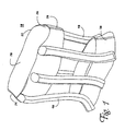
- FIG. 1 there is depicted at 10 a generalized perspective illustration of a first embodiment of the inflatable traction device of the invention, presented with a level of detail sufficient to inform the skilled practitioner of the concept and the practice of the invention.
- the embodiment illustrated in FIG. 1 is adapted for use as a lumbar traction vest.
- the traction vest of the invention 10 is comprised of an upper horizontal support member 20, a lower horizontal support, or belt, member 30, and a plurality of individual, vertically-inflatable support members 40.
- the embodiment of the present invention provides a generalized level of detail.
- the upper horizontal support member 20 is depicted as a unit of one-piece construction. In practice, there are a variety of constructions that are functional for the upper horizontal support member 20. To one of ordinary skill in the appropriate area of art, it will be apparent that the choice of which of these various methods of construction are utilized to prepare an embodiment of the present invention will be determined by such factors as available materials, cost, durability, comfort, and the like. Perhaps the simplest method of construction for the upper torso member 20 would be to utilize an elasticized material such as would be used in the fabrication of support undergarments.
- the upper horizontal support member has a top edge 22.
- the contour followed by the top edge 22 is designed to allow the arms of the wearer to extend comfortably above the upper member 20.
- the upper horizontal support member has a right arm access contour 24, and a left arm access contour 26. If a one-piece unitary construction is utilized for the upper horizontal support member 20, then it is anticipated that the lumbar traction vest of the present embodiment of the invention would be donned by the wearer by first slipping the arms and head through the upper support member 20.
- a key consideration to weigh in the selection of design materials and in the actual construction of the upper member would be the ultimate comfort of the wearer. This comfort would depend to a large extent on the degree of flexibility of the material of construction of the upper horizontal support member 20, as well as the size of the wearer and the actual fabric of construction. It will be recognized that certain materials of construction, such as certain kinds of plastic and the like, would have lower degrees of flexibility and also could prove to be uncomfortable to the wearer in that they would make it difficult for circulation of air between the inside surface 28 of the upper member, and the outer surface of the wearer. Of additional consideration in this regard would be the ability of the material of construction to "breath" sufficiently to allow the passage of moisture from the skin of the wearer to the atmosphere. With this in mind, materials such as Plastics would be less suitable than the type of flexible fabric material normally associated with elasticized support undergarments.
- the upper support member 20 could be constructed of a semi-flexible material, or even a canvas or nylon of sufficient strength, with an opening disposed either to the front, to the rear, or to either side of the torso, wherein the opening may be secured by adjustable means such as laces, buckles, or VelcroTM-type hook and loop closures. With a construction requiring closure in such fashion, the wearer could don the vast in a simpler manner, one that is similar to donning a regular garment. Construction of the upper support member 20 requiring closure in this manner would also provide additional means to adjust the fit of the vest to the wearer, if necessary. As will be apparent from the description below, the fit of the upper member can be critical in that it is an essential element in the transfer of gravitational forces to the proper structural elements of the vest of the present embodiment.
- a lower horizontal support, or belt, member 30 is depicted in FIG. 1 in a single unitary construction. Although it is theoretically possible, utilizing materials of sufficient flexibility and stretch, to so construct the lower horizontal member, preferably it is advisable to construct the lower member along the lines of a conventional front-buckling belt for the embodiment depicted in FIG. 1. Once again, both the specifics of construction, as well as the material choices, for the lower horizontal member 30 depend upon a number of practical factors, such as availability, comfort, cost, and the like. It is contemplated that the lower support or belt member 30 can most practically be constructed from readily available weight-supporting belts such as those utilized in conjunction with external frame backpacks.
- these types of belts are designed to distribute the bulk of the gravitational forces exerted through the entire apparatus to a portion of the wearer's body, namely the hips, that is best suited to bear that load. These types of belts are typically worn fairly low on the hips and are tightened snugly thereto to ensure that the distribution of forces is accomplished in an efficient and effective manner.
- the lower horizontal support member 30 of the lumbar traction vest 10 is designed to receive the bulk of the weight-related forces acting on the vest 10, and transfer those forces to the wearer's hips. It should be recognized here that the phenomenon that occurs through this weight transfer mechanism is essentially the same phenomenon that produces the therapeutic effect of large traction appliances used in clinical settings.
- the weight of the upper body of the wearer is essentially hung from the upper torso member 20, and distributed through the support members 40 to the lower belt member 30.
- the weight forces normally experienced by the spinal region affected by this or any other embodiment of the present invention are instead carried by anatomical structures, such as the hips of the wearer for the lumbar vest, best suited for carrying such a load, leaving the vertebrae of the effected spinal region free from compressional and torsional stress and, therefore, allowing injured spinal anatomy a chance to heal properly.
- FIG. 2 there is illustrated a lateral view of the human spine comprising thirty-three bones -- seven of the cervical region 31, twelve of the thoracic region 33, and the five of the lumbar vertebrae 35, with the latter merging andwardly into the five fused sacral 37, and the four fused coccyx vertebrae 39.
- the relationship between the various spinal regions and the ribs is illustrated in FIG.
- FIG. 3 where, in panel A, there is illustrated a lateral view of the ribs, along with the associated spinal regions, primarily the thoracic 33.
- FIG. 3B there is illustrated a partial sectional view of the skeletal anatomy of the ribs and spine, taken along line 3-3 of FIG. 3A.
- the ribs including the lowest "false" ribs, are integral with the twelve thoracic vertebrae.
- the upper horizontal support member 20 effectively grasps the ribs primarily, although not exclusively, along the lower region. This "grabbing" of the ribs is the initial step in the mechanical transfer of forces away from the lumbar region of the spine. In this fashion, the ribs "grabbed” by the upper horizontal support member act as a lever to transfer the applied forces to and from the upper spinal region, most probably the T1 to T5 vertebrae and associated rib structure.
- the vertically-oriented support members 40 form the next link in the mechanical chain through which forces are removed from the lumbar region of the spine. Ultimately, through the inflatable support members 40, the forces that are normally borne by the lumbar vertebrae 35 and associated disk anatomy are transferred to the lower horizontal member 30 and onto the wearer's hips.
- the structure of the upper horizontal support member or members 20 must meet the relatively simple criterion of being able to effectively and firmly grasp the rib cage so as to use the ribs to lever the applied forces to end from the upper thoracic vertebrae.
- this criterion a wide range of structural arrangements for the upper support member 20 are possible.
- the principal benefit of this design flexibility is that the device of the invention is capable of being fabricated in a lightweight and comfortable form, appropriate for ambulatory use over extended periods of time.
- the construction of the lumber traction vest 10 of the above-described embodiment is such that the vest possesses sufficient flexibility to allow the wearer to engage in a reasonable range of physical activity, all without imparting undue stress to the injured spinal region.
- This same principle is in operation, although to a less noticeable extent, for embodiments of the invention designed to affect the cervical region of the spine.
- the vertical inflatable support members 40 As discussed immediately above, key elements in accomplishing the transfer of forces in the traction vest embodiment to the lower support member, while at the same time maintaining flexibility of the vest that permits the wearer to engage in moderate levels of physical activity, are the vertical inflatable support members 40. As illustrated in FIG. 1, the inflatable lumbar traction vest 10 of the instant embodiment is shown with five vertical support members 40. Although the exact number of support members 40 incorporated into the design of the traction vest 10 is important, it is not critical to achieving the desired function of the vest that there specifically be five vertical members. The inventor considers five vertical members to be an ideal, although not essential, configuration. Such a number of support members 40 provides sufficient support between the upper and lower members of the vest, as well as allowing for sufficient flexibility to permit the wearer a reasonable range of activities while wearing the vest.
- the most critical factor is the total amount of force which the device must be able to apply to the affected region of the spine.
- the most practical starting point for determining the force that needs to be applied, and from that the optimal number of vertical support members is a direct comparison to the type of traction appliances referred to above with respect to the discussion of U.S. Patent No. 4,269,179 to Burton et al.
- the maximum amount of force that could be applied to a patient's lumbar spinal region would be equal to approximately 40-50% of that patient's body weight.
- the actual number of vertical support members 40 can be fewer than five, or more than five. Generally speaking, it would be undesirable for the number of support members to be less than four. With a configuration of four vertical support members, these would preferably be distributed with two in the front of the vast and two in the rear of the vast. It is also possible to have more than five members, such as six, where the plurality of vertical support members 40 would be distributed equally between the front and back portions of the vest 10.
- vertical support members 40 may be desirable for some applications where greater levels of constraint of movement may be preferable, such as those designed to correct deviations in spinal conformation typical of conditions such as scoliosis, lordosis or kyphosis.
- a significant, advantageous feature of the vertical orientation of the support members of the invention lies in the fact that such an orientation leads directly to the mechanical distribution of forces vertically within the vest 10. This is achieved through a vertical distribution forces through the support members that effectively results in the suspension of a major proportion of the wearer's body weight from the upper horizontal support member which weight, in turn, is transferred to and supported by the lower horizontal support member or belt, in the case of the traction vest embodiment.
- Alternative orientations of support members for example in a horizontal orientation or in a torroidal configuration, could lead directly to spinal compression, as opposed to spinal support or re-distribution of forces acting on the spine.
- fluid filling of a horizontally-oriented bladder system could result in the same type of effect evidenced with prior art corset-type braces discussed above which can significantly immobilize the wearer. It is contemplated that a similar effect could result from the use of too many vertical members in the design of the vast of the present invention.
- the plurality of vertical support members 40 are of approximately equal diameter, which diameter is preferably about 1 inch or more, although individual members may have a slightly different conformation depending upon their relative positions on the vest 10.
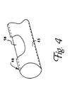
- Essential to the effective function of these vertical support members are the fluid-fillable bladders 50, as illustrated in FIG. 4 in partial cut-away section.
- the embodiment of the present invention illustrated in FIG. 4 contemplates but a bladder 50 present in each of the vertical support members 40.
- a plurality of essentially cylindrical bladders to be utilized in each vertical support member 40, each of the plurality in fluid communication so that a single source of air or other suitable fluid would be capable of filling the plurality of bladders 50 in a single vertical support member 40 to a desired pressure.
- the bladders can be constructed of a bellows design to further aid in the upward vertical expansion, and subsequent vertical distribution of forces, of the support members 40.
- the individual bladders may be advantageously constructed with at least one bellows portion 55, although it is possible to construct any one bladder 50 with a plurality of such bellows portions.
- the bladders 50 may be constructed of a variety of materials possessing the desirable characteristics of flexibility and strength. However, it is contemplated that the preferable material of construction of the bladders 50 be latex due to the ease of fabrication possible with such material. Such material can be fabricated into appropriate bladders by specialty manufacturers such as North American Latex of Sullivan, Indiana. As contemplated by this embodiment of the present invention, the diameter of the bladders 50 controls the diameter of the support members 40. Given the use of latex as the material of the bladders, a maximum practical diameter of the cylindrically-shaped bladders would be about 1 inch. Latex bladders of this diameter would be safely capable of filling to a maximum pressure of approximately 14 kPa (20 lbs/in 2 ).
- the bladders 50 it is necessary to fill the bladders 50 only to a pressure in the range of 4.2-8.4 kPa (6-12 lbs/in 2 ) (see Eq. (3)) to achieve the desired mechanical characteristics of the vertical support members, at least for the majority of contemplated applications of the lumbar traction vest embodiment. Variation in the range of inflation pressure can also be achieved through selection of the material of construction of the bladders, as well as the number of vertical support members 40 utilized on the vest, and the number of bladder segments within any one support member 40. In the context of fluid pressure, it is important to remember that it is desired to retain a sufficient degree of flexibility in the fully filled vest so that the wearer will not be so constrained in movement as to be practically immobile.
- the wearer For the majority of applications contemplated for the vest embodiment 10, it will remain preferable for the wearer to be free to engage in a reasonable degree of physical movement while wearing the vest. This is where selection of the material of construction of the bladders 50 becomes important; latex is particularly advantageous in that it is capable of maintaining sufficient flexibility when inflated to the desired level of pressure.
- the means for constraining radial inflation could be the outer portion 43 of the vertical support members 40. It could also be provided by a sheath surrounding the bladders 50, where the sheath is fabricated of a sufficiently stiff material. It is also possible that the walls of the bladders themselves could be integrally constructed with a material capable of vertical expansion but more severely constrained in the horizontal direction during filling.
- additional support means serve the purpose of importing additional stiffness, and therefore support, to the vertical support means.
- Suitable material of construction for these additional support means may be wood, plastic or even metal.
- the individual additional support means may then be advantageously fabricated to a contour that matches the wearer's body contours. It is also possible to fabricate individual bladders 50 incorporating support means in the form of a flexible fabric material integrally constructed with the walls of the bladder.
- the additional support means may be constructed of a less flexible, stiffer material, preferably premolded to a desired conformation.
- An additional consideration in the function of the vertical support members is the material of construction of the outer portion 43 of the members 40.
- the specific material of construction chosen here is less critical than the choice of bladder material and will typically be driven by cost, availability and, to a lesser extent, comfort. It is possible for the outer portion of the vertical members to be constructed from such materials as canvas or nylon, although nylon would be preferable due to weight considerations.
- An additional function of the outer portion 43 of the vertical members 40, as mentioned above, is to constrain the inflation of the bladders 50 and to physically limit the expansion of the flexible bladders in a radial direction upon inflation, making possible the vertical distribution of forces.
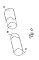
- the vertical support members 40 can be mechanically affixed to the upper support member 20 and the lower member by a variety of means. As illustrated in FIG. 6, each end of the vertical support members is placed in receiving cup members 45 permanently affixed to the vertical members of the vest by a variety of means, such as gluing, sewing, and the like. It is also contemplated that the vertical support members can be directly coupled to the horizontal members of the vest 20 without the use of receiving cup members. It is also contemplated that the overall design of the vest embodiment be more unitary than is apparent from the depiction in FIG. 1.
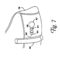
- FIG. 7 Illustrated therein is a hand pump mechanism shown generally at 60.
- This pump mechanism 60 comprises a removable pumping bulb 62, a pressure fitting 64, and a bladder access port 66.
- the bladder access port is, in turn, in fluid communication with a bladder channel 68 through which fluid is forced by hand squeezing of the pumping bulb 62.
- Such pressure fitting for gaseous fluids, could be a common Schraeder-type valve typically found on bicycle and car tires. With such a fitting, pressure inside the bladders could be relieved through the simple act of depressing the central valve stem in the fitting.
- a VelcroTM-type hook and loop closure (not shown) could be provided to cover the non-removable components of the inflation mechanism 60 when not in use.
- this general type of a filling mechanism contemplates the use of a gas such as air as the preferred fluid for the bladders.
- a gas such as air
- other fluids either gases or liquids at room temperature, may be utilized as the filling fluid in the practice of the preferred embodiments of the present invention.
- Preference for the use of a gas such as air arises from the ready availability of the gas and it ease of mechanical utilization.
- conditions would arise in which the use of alternative, non-gaseous fluids would provide sufficient additional advantages as to dictate their use.
- each of a plurality of inflation mechanisms 60 be in fluid communication with each of a plurality of bladders distributed throughout the vertical support members. In this fashion, it would be possible to selectively tailor the filling pressure within the device to provide lesser pressure in some regions of the device, and greater pressure in others. It is contemplated that this type of custom adjustment of the bladder system of the device of the invention could be achieved to result in whatever degree of motion would be desired for a particular activity contemplated for the wearer. The number and distribution of such separate bladders within the bladder system of the vest would be limited by such practical considerations as the complexity of manufacture, the resulting costs of multiple-component systems, and the specific applications of the device. In addition, it is contemplated that and additional bladder, preferably in fluid communication with one or more of the vertically-oriented bladders, be placed so as to conform to the unique geometry of the lumbar curvature of the wearer's back.
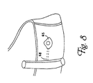
- FIG. 8 The mechanism contemplated here is a completely enclosed pump means 65 which is activated by downward pressure of the wearer's thumb on the convex surface of the pump means.
- a completely enclosed pump means 65 which is activated by downward pressure of the wearer's thumb on the convex surface of the pump means.
- Such systems find frequent use in gas-inflatable sporting apparati.
- hand-operated pressure release valves (not shown) so that the gas pressure within the bladders 50 may be relieved to facilitate the removal of the vest 10 from the wearer.
- the vest of this embodiment of the present invention provides an ideal means for such long-haul drivers to avoid injury to their lower backs, as well as aggravation of existing injuries during long hours behind the wheel.
- a significant advantage of the lumbar vest embodiment of the present invention, as described above, is that it is capable of being worn during a wide range of physical activity. Furthermore, it is comfortable enough to be worn for relatively long periods of time so that, even if the degree of therapeutic effect does not rise to the level associated with clinical traction appliances, the overall effect of the use of the vest embodiment of the invention can match or exceed that of the large appliances. Such characteristics make the vest of the present invention ideally suited for use by long haul truckers.
- Most large tractor/trailer combinations employ a compressed air apparatus associated with the brake system of the truck. It is relatively easy to utilize a means to tap into that source of pressurized gas and extend a hose and coupling means into the cabin of the truck for inflation of the bladders of the vest while the wearer is driving the truck. Connection to the compressed air system of the truck can ba achieved by mechanical hose coupling devices such as a luer lock fitting.
- the wearer can inflate the vest while driving to a level of pressure that is personally comfortable, arrive at the scheduled destination, further adjust the inflation level using the air hose means, and then immediately upon parking the truck, begin to unload cargo while still wearing the vest of the invention, and after uncoupling from the air hose means.
- the embodiments of the present invention disclosed herein are uniquely capable due to their light weight and flexibility to meet various federal and state drivers' safety requirements for devices worn while operating commercial vehicles in the transport of goods in commerce.
- the present invention contemplates the use of a check valve associated with each separate fluid flow/bladder system within the vest so that there is no chance of an over-filling occurring during wearing of the vest.
- Valves of this nature are well-known in the-art. Typically, such valves can be selected or set to match the maximum rated inflation pressures of the individual bladders. Thus, when the pressure rises to the safe limit of a bladder, either during filling or during use, the check valve will activate to relieve the buildup of pressure before damage can occur to the vest, or injury to the wearer.
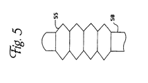
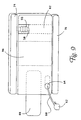
- FIG. 9 illustrates an alternative embodiment of the present invention, shown generally at 70, designed to affect the cervical region of the spine.
- the cervical brace 70 is shown in a generalized, almost schematic, fashion designed to illustrate the main elements of the brace on a level of gross detail.
- FIG. 9 illustrates that the cervical brace 70 is comprised of at least three major components, an upper, mandible support member 74, a lower, clavicle support member 76, and a central bladder-containing portion 78. Disposed within the central bladder-containing portion 78 are a plurality of individual, vertically-oriented bladders 50, shown in FIG. 9, in partial cutaway view, with an optional bellows portion 55. The number and diameter of such bladders 55 can be calculated in accord with Eq.
- the central bladder-containing portion 78 of the present embodiment is subject, as with the previous embodiment, to substantial variability, as will be recognized by one of skill in the appropriate art. It is contemplated that the central portion 78 be constructed of a flexible fabric material onto which are affixed separate chambers within which are contained each of the plurality of bladders 50. It is also contemplated, by way of example only and without limitation, that the central portion 78 may be constructed of a foam material from which are excised suitable volumes for containing the vertically-expanding bladders 50.
- the central bladder-containing portion 78 of the cervical brace 70 also comprises a support region 86 disposed to be oriented to the back of the wearer's neck and designed to provide sufficient support in a front-to-back plane so as to restrict the range of motion to the rear of the wearer's head. Also shown in FIG. 9 is a means 88 for adjustably fastening the cervical brace 70 around a wearer's neck.
- gaseous fluids are contemplated as the preferred fluids for filling the bladders of the present embodiment of the invention, it should be recognised that, as is the case with the vast embodiment designed to affect the lumbar region of the spine, a variety of fluids may be used, including those that are in liquid phase under conditions of normal use. Based upon analogy to existing mechanical traction devices, an optimal total force to be achieved for cervical traction through use of this embodiment of the present invention would be approximately 6.8-11 N (15- 25 pounds).
- Such an inflation mechanism comprises similarly-numbered elements as that for the mechanism of the embodiment of FIG. 7.
- FIG. 9 illustrates the upper and lower support members of the cervical brace 70 at a gross level of detail only.
- each of the horizontally-disposed support members of the brace comprise additional detail, as would be appreciated by a skilled practitioner.
- the upper or mandible support member may be contoured to fit the anatomical details of the wearer's chin and jaw area in order to attain a more effective fit of the brace to the individual wearer.
- the upper support member 74 will be fabricated preferably of a relatively dense plastic foam in order to both provide support and resistance to the vertically-directed forces acting through the brace, at the same time as providing comfort to the wearer.
- the upper support member 74 may be covered with a comfortable, breathable fabric because it will be in direct contact with the wearer's skin for a segment of the support member's length.
- the lower or clavicle support member 76 is also illustrated in FIG. 9 at a level of gross detail only. It is contemplated that this portion of the cervical traction brace 70 may assume a plurality of embodiments, In one embodiment, it may be constructed in a similar manner and of a similar material as the upper support member 74. Alternatively, it may also comprise an fluid-inflatable bladder, either with separate filling means, or in direct fluid contact with the bladder system of the central bladder-containing portion 78. Regardless of the actual manner of construction selected for either of the two horizontally-directed support members of the cervical brace 70, they must be designed so as to be able to withstand, and transmit where appropriate, the traction forces acting vertically through the brace.
- the cervical traction brace of FIG. 9 functions on identical principles to those described for the previous embodiment.
- the bladders As the bladders are filled to a desired pressure, they expand vertically, exerting traction forces on the cervical region of the wearer's spine.
- the weight of the wearer's head is supported by the upper or mandible support member 74 and transmitted through the central bladder-containing portion 78 to the lower or clavicle support member.
- the gravitational forces acting on the wearer's cervical spinal region are relieved and actually borne by the wearer's upper chest and shoulder area, depending on the specific design of the lower support member.
- the end result is essentially identical to that obtained with the type of mechanical cervical traction devices described in the Background of the Invention section, supra.
- the advantage, therefore, of the present invention is that the therapeutic gains to be realized from traction treatment can be achieved without resort to immobilizing the patient, with a resultant loss of productive time.
Claims (12)
- Eine ambulante Wirbelsäulentraktionsvorrichtung (10) zum Zuführen primär vertikal gerichteter Kräfte zu einer anatomischen Region einer menschlichen Wirbelsäule, wobei die Vorrichtung
mindestens ein oberes horizontales Stützelement (20),
-mindestens ein unteres horizontales Stützelement (30) und
eine Mehrzahl aufrechter Stützelemente (40), die jeweils feststehend an einem ersten Ende und einem zweiten Ende an dem mindestens einen oberen Stützelement (20) und dem mindestens einen unteren Stützelement (30) befestigt sind, wobei jedes der Mehrzahl aufrechter Stützelemente (40) darin mindestens eine füllbare Blase (50) enthält, wobei die mindestens eine Blase (50) jedes der Mehrzahl aufrechter Stützelemente (40) in Fluidverbindung mit einer Fülleinrichtung (60) ist, und
Mittel zum Verbinden des mindestens einen oberen horizontalen Stützelements (20) und des mindestens einen unteren horizontalen Elements (30) umfasst, dadurch gekennzeichnet, dass
die aufrechten Stützelemente (40) vertikal und sowohl hinten als auch vorne an den oberen und unteren horizontalen Stützelementen (20, 30) verteilt sind, und wobei jedes vertikale Stützelement (40) von einem angrenzenden vertikalen Stützelement (40) in einem vorbestimmten Abstand beabstandet ist, so dass der Vorrichtung eine Gesamtflexibilität verliehen wird. - Vorrichtung nach Anspruch 1, wobei die Region einer menschlichen Wirbelsäule, auf die Kräfte ausgeübt werden, aus der Gruppe bestehend aus der Halsregion (31), der Brustregion (33) und der Lendenregion (35) ausgewählt ist.
- Vorrichtung nach Anspruch 1, bei der die vertikalen Stützelemente (40) eine vertikale Komponente der Kräfte, die auf die anatomische Region einer Wirbelsäule ausgeübt werden, im Bereich von etwa 6,8 bis 45 N (15 bis etwa 100 Pfund) liefern.
- Vorrichtung nach Anspruch 1, bei der die vertikalen Stützelemente (40) eine vertikale Komponente der Kräfte, die auf die anatomische Region einer Wirbelsäule ausgeübt werden, im Bereich von etwa 6,8 bis 11 N (15 bis etwa 25 Pfund) liefem.
- Vorrichtung nach Anspruch 4, bei der die vertikalen Stützelemente (40) Kräfte liefern, die auf die Halsregion (31) einer Wirbelsäule ausgeübt werden.
- Vorrichtung nach Anspruch 1, bei der die vertikalen Stützelemente (40) eine vertikale Komponente der Kräfte, die auf die anatomische Region einer Wirbelsäule ausgeübt werden, im Bereich von etwa 23 bis 45 N (50 bis 100 Pfund) liefern.
- Vorrichtung nach Anspruch 6, bei der die vertikalen Stützelemente (40) Kräfte liefern, die auf die Lendenregion (36) einer Wirbelsäule ausgeübt werden.
- Vorrichtung nach-Anspruch 1; bei der die Mehrzahl vertikaler Stützelemente (40) vier bis sechs Elemente umfasst.
- Vorrichtung nach Anspruch 1, bei der mindestens eines der horizontalen Stützelemente (20, 30) eine aufblasbare Blase in Fluidverbindung mit einer Aufblaseinrichtung umfasst.
- Vorrichtung nach Anspruch 1, bei der die Vorrichtung (10) ferner eine aufblasbare Blase umfasst, die so positioniert ist, dass sie mit der Lendenregion (35) der Wirbelsäule eines Trägers ausgerichtet ist.
- Vorrichtung nach Anspruch 1, bei der die Fülleinrichtung (60) eine manuelle Luftpumpe (62) ist.
- Vorrichtung nach Anspruch 1, bei der die Fülleinrichtung (60) ein Druckluftsystem ist.
Applications Claiming Priority (5)
| Application Number | Priority Date | Filing Date | Title |
|---|---|---|---|
| US474780 | 1983-03-14 | ||
| US47478095A | 1995-06-07 | 1995-06-07 | |
| US08/580,708 US5724993A (en) | 1995-06-07 | 1995-12-29 | Inflatable spinal traction device |
| US580708 | 1995-12-29 | ||
| PCT/US1996/009881 WO1996040036A1 (en) | 1995-06-07 | 1996-06-06 | Ambulatory spinal traction device |
Publications (3)
| Publication Number | Publication Date |
|---|---|
| EP0837666A1 EP0837666A1 (de) | 1998-04-29 |
| EP0837666A4 EP0837666A4 (de) | 2000-01-05 |
| EP0837666B1 true EP0837666B1 (de) | 2004-02-11 |
Family
ID=27044571
Family Applications (1)
| Application Number | Title | Priority Date | Filing Date |
|---|---|---|---|
| EP96923263A Expired - Lifetime EP0837666B1 (de) | 1995-06-07 | 1996-06-06 | Ambulante wirbelsäulenstreckvorrichtung |
Country Status (9)
| Country | Link |
|---|---|
| US (1) | US5724993A (de) |
| EP (1) | EP0837666B1 (de) |
| JP (1) | JP2000507836A (de) |
| AT (1) | ATE259199T1 (de) |
| AU (1) | AU699290B2 (de) |
| DE (1) | DE69631532T2 (de) |
| IL (1) | IL122495A (de) |
| NO (1) | NO310906B1 (de) |
| WO (1) | WO1996040036A1 (de) |
Families Citing this family (40)
| Publication number | Priority date | Publication date | Assignee | Title |
|---|---|---|---|---|
| JP2911437B2 (ja) * | 1997-03-12 | 1999-06-23 | イク チュン チャン | 空気注入式腰部圧迫腹帯 |
| US6126681A (en) * | 1998-08-24 | 2000-10-03 | Augustine Medical, Inc. | Detection of a condition between an inflatable thermal device and an air hose in a convective warming system |
| DE29911206U1 (de) | 1999-06-18 | 1999-10-21 | Hildebrandt Hans Dietrich | Bekleidungsstück und orthopädische Einrichtung dafür |
| US6516804B1 (en) * | 2000-05-03 | 2003-02-11 | Aztec-Life, Inc. | Cardio-thoracic compression harness |
| US6702771B1 (en) | 2001-03-01 | 2004-03-09 | Amei Technologies, Inc. | Canting mechanism for an ambulatory support device |
| US6635025B1 (en) | 2001-03-01 | 2003-10-21 | Amei Technologies, Inc. | Traction device adjustment mechanism and method |
| US6689082B2 (en) * | 2001-03-01 | 2004-02-10 | Amei Technologies Inc. | Traction device |
| US6533740B2 (en) | 2001-03-01 | 2003-03-18 | Amei Technologies Inc. | Lifting mechanism for a traction device |
| US7074201B2 (en) * | 2001-06-18 | 2006-07-11 | Amei Technologies, Inc. | Measurement device for fitting a bracing device |
| US6749579B1 (en) | 2002-08-07 | 2004-06-15 | Mitchell J. Schroder | Traction garment |
| US7276038B2 (en) * | 2003-01-14 | 2007-10-02 | Amei Technologies Inc. | Field adjustable traction device |
| US20060064005A1 (en) * | 2004-09-23 | 2006-03-23 | Innovative Spinal Technologies | System and method for externally controlled surgical navigation |
| US20060161083A1 (en) * | 2005-01-15 | 2006-07-20 | Dunfee Matthew J | Ambulatory spinal unloading method and apparatus |
| US20080033251A1 (en) * | 2006-06-30 | 2008-02-07 | Ali Araghi | Surgical retractor and method of use |
| US8062217B2 (en) * | 2007-01-26 | 2011-11-22 | Theken Spine, Llc | Surgical retractor with removable blades and method of use |
| US20080183044A1 (en) * | 2007-01-26 | 2008-07-31 | Dennis Colleran | Flexible surgical retractor and method of use |
| DE102008009505A1 (de) * | 2008-02-15 | 2009-08-20 | Valerie Bodrov | System zur Kontrolle der Stellung der Wirbelsäule |
| US20090275871A1 (en) * | 2008-05-02 | 2009-11-05 | Gerald Liu | Back brace for spinal correction and its manufacturing method |
| US20090306568A1 (en) * | 2008-06-09 | 2009-12-10 | Meyer Donald W | Intermittent lumbar traction apparatus and method |
| US20090306567A1 (en) * | 2008-06-09 | 2009-12-10 | Meyer Donald W | Cervical spine traction apparatus and method |
| JP2010000196A (ja) * | 2008-06-19 | 2010-01-07 | Nobuyuki Tsuzuki | 脊柱治療用コルセット |
| EP2400936B1 (de) | 2009-02-26 | 2015-09-09 | Össur HF | Orthopädische vorrichtung zur behandlung des rückens |
| US8657769B2 (en) | 2009-11-04 | 2014-02-25 | Ossur Hf | Thoracic lumbar sacral orthosis |
| US8556840B2 (en) * | 2009-12-22 | 2013-10-15 | Aspen Medical Partners, Llc | Hyperextension brace |
| US20110181089A1 (en) * | 2010-01-25 | 2011-07-28 | Litesitter Llc | Portable device for unloading lower back while sitting |
| JP2012147912A (ja) * | 2011-01-18 | 2012-08-09 | Tomoaki Saito | 腰痛改善作業用装具 |
| CN103747763B (zh) | 2011-06-20 | 2016-03-30 | 奥索有限责任公司 | 矫形装置、矫形装置的使用及其制造方法 |
| WO2013106666A1 (en) | 2012-01-13 | 2013-07-18 | Ossur Hf | Spinal orthosis and method for using the same |
| US9572705B2 (en) | 2012-01-13 | 2017-02-21 | Ossur Hf | Spinal orthosis |
| CN104853699B (zh) | 2012-09-19 | 2017-08-15 | 欧苏尔公司 | 用于矫形装置的嵌板附着件与周长调整系统 |
| US10357391B2 (en) | 2013-01-24 | 2019-07-23 | Ossur Hf | Orthopedic device for treating complications of the hip |
| EP2948107B1 (de) | 2013-01-24 | 2018-07-11 | Össur HF | Orthopädische vorrichtung zur behandlung von komplikationen der hüfte |
| US9795500B2 (en) | 2013-01-24 | 2017-10-24 | Ossur Hf | Orthopedic device for treating complications of the hip |
| US9554935B2 (en) | 2013-01-24 | 2017-01-31 | Ossur Hf | Orthopedic device for treating complications of the hip |
| SG11201609609TA (en) * | 2014-06-12 | 2016-12-29 | Univ Singapore | Actuator device, method and system for limb rehabilitation |
| US10561520B2 (en) | 2015-02-27 | 2020-02-18 | Ossur Iceland Ehf | Spinal orthosis, kit and method for using the same |
| EP3261590B1 (de) | 2015-02-27 | 2020-08-19 | Ossur Iceland EHF | Wirbelsäulenorthese und bausatz mit einer wirbelsäulenorthese |
| CN105287068A (zh) * | 2015-10-16 | 2016-02-03 | 陈靖军 | 一种腰椎减负装置 |
| US11246734B2 (en) | 2017-09-07 | 2022-02-15 | Ossur Iceland Ehf | Thoracic lumbar sacral orthosis attachment |
| WO2019067835A1 (en) | 2017-09-28 | 2019-04-04 | Ossur Iceland Ehf | BODY INTERFACE |
Family Cites Families (31)
| Publication number | Priority date | Publication date | Assignee | Title |
|---|---|---|---|---|
| US1589670A (en) * | 1924-11-15 | 1926-06-22 | Alf C Kremer | Pneumatic stretcher |
| US3186405A (en) * | 1962-11-13 | 1965-06-01 | Robert E Bailey | Inflatable splint |
| US3868952A (en) * | 1971-12-14 | 1975-03-04 | Aerazur Constr Aeronaut | Inflatable shaped structures |
| FR2298314B1 (fr) * | 1975-01-24 | 1980-03-28 | Inst Nat Sante Rech Med | Appareils orthopediques pneumatiques composes de plusieurs elements articules |
| US4269179A (en) * | 1976-05-05 | 1981-05-26 | Abbot-Northwestern Hospitals Inc. | Orthopedic gravity traction brace |
| DE3125588A1 (de) * | 1981-06-30 | 1983-01-13 | Daimler-Benz Ag, 7000 Stuttgart | "im rueckenlehnenbereich eines kraftwagensitzes verdeckt angeordnetes kissen" |
| FR2529455A1 (fr) * | 1982-07-01 | 1984-01-06 | Arlux Sa | Lombostat a assemblage d'elements semi-rigides et pelote gonflable |
| US4624248A (en) * | 1983-02-07 | 1986-11-25 | David Clark Company Incorporated | Transparent pressure garment |
| US4552135A (en) * | 1984-03-05 | 1985-11-12 | Racz Gabor B | Lumbar belt |
| US4622957A (en) * | 1984-07-03 | 1986-11-18 | Curlee James D | Therapeutic corset |
| US4691696A (en) * | 1985-02-01 | 1987-09-08 | 102160 Canada Inc. | Lumbar spinal brace |
| US4682588A (en) * | 1985-05-07 | 1987-07-28 | Pneumedic Corp. | Compound force therapeutic corset |
| US4702235A (en) * | 1986-05-17 | 1987-10-27 | Hong James K | Therapeutic inflatable lumbar brace having a heater |
| US4685668A (en) * | 1986-10-30 | 1987-08-11 | Newlin Jr Thomas L | Weightlifting belt |
| US4768499A (en) * | 1987-02-17 | 1988-09-06 | Kemp Kenneth A | Back and abdominal muscle supporting belt |
| JPH03501567A (ja) * | 1987-07-02 | 1991-04-11 | ランドン‐オーラ,ケリル ラルダ | 副木方法、副木およびストラップ |
| US4960115A (en) * | 1988-08-05 | 1990-10-02 | Peter Ranciato | Body support apparatus |
| US5062414A (en) * | 1989-02-08 | 1991-11-05 | Royce Medical Company | Simplified orthopaedic back support |
| US4898185A (en) * | 1989-02-24 | 1990-02-06 | Life Support, Inc. | Back traction device for use with chairs |
| US4991572A (en) * | 1989-10-30 | 1991-02-12 | Chases Ronald L | Lumbar traction device |
| US5060639A (en) * | 1990-01-31 | 1991-10-29 | Helen A. Siudyla | Back support |
| US4991573A (en) * | 1990-03-26 | 1991-02-12 | Miller Donald L | Orthopedic support belt |
| US5111807A (en) * | 1990-10-11 | 1992-05-12 | Ehob Inc. | Back belt |
| US5076264A (en) * | 1991-05-28 | 1991-12-31 | Lonardo John S | Medical appliance for treating spinal conditions |
| US5135471A (en) * | 1991-09-09 | 1992-08-04 | R.A. Storrs, Inc. | Cruciform anterior spinal hyperextension orthosis |
| US5188586A (en) * | 1991-10-04 | 1993-02-23 | The Smith Truss Company | Back support belt |
| US5256135A (en) * | 1992-01-23 | 1993-10-26 | Medisol U.S.A., Inc. | Thoracic-lumbar-sacral corrective orthosis ("TLSO") corrective back supporting brace and chair side support buttress |
| US5382226A (en) * | 1993-02-12 | 1995-01-17 | Graham; Richard A. | Inflatable cervical traction and exercising device |
| US5338289A (en) * | 1993-03-29 | 1994-08-16 | Cooker John T | Spinal support for reclining persons |
| US5403266A (en) * | 1993-07-06 | 1995-04-04 | United States Manufacturing Company | Inflatable cervical traction collar |
| US5441479A (en) * | 1993-09-13 | 1995-08-15 | Glacier Cross, Inc. | Cervical traction device |
-
1995
- 1995-12-29 US US08/580,708 patent/US5724993A/en not_active Expired - Lifetime
-
1996
- 1996-06-06 DE DE69631532T patent/DE69631532T2/de not_active Expired - Fee Related
- 1996-06-06 EP EP96923263A patent/EP0837666B1/de not_active Expired - Lifetime
- 1996-06-06 AU AU63824/96A patent/AU699290B2/en not_active Ceased
- 1996-06-06 JP JP9502066A patent/JP2000507836A/ja active Pending
- 1996-06-06 IL IL12249596A patent/IL122495A/en not_active IP Right Cessation
- 1996-06-06 AT AT96923263T patent/ATE259199T1/de not_active IP Right Cessation
- 1996-06-06 WO PCT/US1996/009881 patent/WO1996040036A1/en active IP Right Grant
-
1997
- 1997-12-05 NO NO19975754A patent/NO310906B1/no not_active IP Right Cessation
Also Published As
| Publication number | Publication date |
|---|---|
| JP2000507836A (ja) | 2000-06-27 |
| DE69631532T2 (de) | 2005-01-05 |
| NO975754D0 (no) | 1997-12-05 |
| IL122495A (en) | 2002-04-21 |
| NO975754L (no) | 1998-02-09 |
| AU6382496A (en) | 1996-12-30 |
| EP0837666A1 (de) | 1998-04-29 |
| ATE259199T1 (de) | 2004-02-15 |
| DE69631532D1 (de) | 2004-03-18 |
| WO1996040036A1 (en) | 1996-12-19 |
| EP0837666A4 (de) | 2000-01-05 |
| US5724993A (en) | 1998-03-10 |
| IL122495A0 (en) | 1998-06-15 |
| NO310906B1 (no) | 2001-09-17 |
| AU699290B2 (en) | 1998-11-26 |
Similar Documents
| Publication | Publication Date | Title |
|---|---|---|
| EP0837666B1 (de) | Ambulante wirbelsäulenstreckvorrichtung | |
| US5704904A (en) | Inflatable lumber traction vest | |
| US5950628A (en) | Inflatable wearable traction device | |
| US20210113359A1 (en) | Spinal orthosis | |
| US5462518A (en) | Therapeutic spinal traction apparatus and multipurpose exercise systems and methods | |
| US5007633A (en) | Spinal column support attachments for a weight lifter's bench | |
| US6942630B2 (en) | Inflatable suspension harness/body jacket | |
| US4759543A (en) | Passive exercise cushion | |
| US5295947A (en) | Chiropractic brace | |
| US11103743B2 (en) | Joint separator for body alignment | |
| US7150719B2 (en) | Thoraco-lumbar spine support/brace | |
| JPH07503647A (ja) | 固定ベルトに取外し可能に固定される腰部支持体 | |
| US6280405B1 (en) | Device for stationary and/or ambulant traction of the spinal column | |
| US6896662B2 (en) | Method for lordosis adjustment for treating discomfort in, or originating in, the cervical spine region | |
| US20040073150A1 (en) | Ambulatory trans-lumbar traction system | |
| US4583533A (en) | Orthopedic lumbar apparatus | |
| US20030130696A1 (en) | Method and portable apparatus for spinal adjustment | |
| US20220409417A1 (en) | Adjustable Therapeutic Scoliosis Brace | |
| WO1998033456A9 (en) | Inflatable wearable traction device | |
| WO1998033456A1 (en) | Inflatable wearable traction device | |
| Sypert | External spinal orthotics | |
| CA2228468C (en) | Ambulatory spinal traction device | |
| EP0959826B1 (de) | Vorrichtung zur stationären und/oder ambulanten strechung der wirbelsäule | |
| Hart et al. | Review of cervical orthoses | |
| US20040167449A1 (en) | Appliance for lordosis adjustment for treating discomfort in, or originating in, the cervical spine region |
Legal Events
| Date | Code | Title | Description |
|---|---|---|---|
| PUAI | Public reference made under article 153(3) epc to a published international application that has entered the european phase |
Free format text: ORIGINAL CODE: 0009012 |
|
| 17P | Request for examination filed |
Effective date: 19980107 |
|
| AK | Designated contracting states |
Kind code of ref document: A1 Designated state(s): AT BE CH DE DK ES FI FR GB GR IE IT LI LU MC NL PT SE |
|
| A4 | Supplementary search report drawn up and despatched |
Effective date: 19991122 |
|
| AK | Designated contracting states |
Kind code of ref document: A4 Designated state(s): AT BE CH DE DK ES FI FR GB GR IE IT LI LU MC NL PT SE |
|
| RIC1 | Information provided on ipc code assigned before grant |
Free format text: 7A 61F 5/02 A, 7A 61F 5/01 B |
|
| 17Q | First examination report despatched |
Effective date: 20020419 |
|
| RAP1 | Party data changed (applicant data changed or rights of an application transferred) |
Owner name: AMEI TECHNOLOGIES INC. |
|
| RAP1 | Party data changed (applicant data changed or rights of an application transferred) |
Owner name: AMEI TECHNOLOGIES INC. |
|
| GRAH | Despatch of communication of intention to grant a patent |
Free format text: ORIGINAL CODE: EPIDOS IGRA |
|
| GRAS | Grant fee paid |
Free format text: ORIGINAL CODE: EPIDOSNIGR3 |
|
| GRAA | (expected) grant |
Free format text: ORIGINAL CODE: 0009210 |
|
| AK | Designated contracting states |
Kind code of ref document: B1 Designated state(s): AT BE CH DE DK ES FI FR GB GR IE IT LI LU MC NL PT SE |
|
| PG25 | Lapsed in a contracting state [announced via postgrant information from national office to epo] |
Ref country code: NL Free format text: LAPSE BECAUSE OF FAILURE TO SUBMIT A TRANSLATION OF THE DESCRIPTION OR TO PAY THE FEE WITHIN THE PRESCRIBED TIME-LIMIT Effective date: 20040211 Ref country code: LI Free format text: LAPSE BECAUSE OF FAILURE TO SUBMIT A TRANSLATION OF THE DESCRIPTION OR TO PAY THE FEE WITHIN THE PRESCRIBED TIME-LIMIT Effective date: 20040211 Ref country code: FI Free format text: LAPSE BECAUSE OF FAILURE TO SUBMIT A TRANSLATION OF THE DESCRIPTION OR TO PAY THE FEE WITHIN THE PRESCRIBED TIME-LIMIT Effective date: 20040211 Ref country code: CH Free format text: LAPSE BECAUSE OF FAILURE TO SUBMIT A TRANSLATION OF THE DESCRIPTION OR TO PAY THE FEE WITHIN THE PRESCRIBED TIME-LIMIT Effective date: 20040211 Ref country code: BE Free format text: LAPSE BECAUSE OF FAILURE TO SUBMIT A TRANSLATION OF THE DESCRIPTION OR TO PAY THE FEE WITHIN THE PRESCRIBED TIME-LIMIT Effective date: 20040211 Ref country code: AT Free format text: LAPSE BECAUSE OF FAILURE TO SUBMIT A TRANSLATION OF THE DESCRIPTION OR TO PAY THE FEE WITHIN THE PRESCRIBED TIME-LIMIT Effective date: 20040211 |
|
| REG | Reference to a national code |
Ref country code: GB Ref legal event code: FG4D |
|
| REG | Reference to a national code |
Ref country code: CH Ref legal event code: EP |
|
| REG | Reference to a national code |
Ref country code: IE Ref legal event code: FG4D |
|
| REF | Corresponds to: |
Ref document number: 69631532 Country of ref document: DE Date of ref document: 20040318 Kind code of ref document: P |
|
| PG25 | Lapsed in a contracting state [announced via postgrant information from national office to epo] |
Ref country code: SE Free format text: LAPSE BECAUSE OF FAILURE TO SUBMIT A TRANSLATION OF THE DESCRIPTION OR TO PAY THE FEE WITHIN THE PRESCRIBED TIME-LIMIT Effective date: 20040511 Ref country code: GR Free format text: LAPSE BECAUSE OF FAILURE TO SUBMIT A TRANSLATION OF THE DESCRIPTION OR TO PAY THE FEE WITHIN THE PRESCRIBED TIME-LIMIT Effective date: 20040511 Ref country code: DK Free format text: LAPSE BECAUSE OF FAILURE TO SUBMIT A TRANSLATION OF THE DESCRIPTION OR TO PAY THE FEE WITHIN THE PRESCRIBED TIME-LIMIT Effective date: 20040511 |
|
| PG25 | Lapsed in a contracting state [announced via postgrant information from national office to epo] |
Ref country code: ES Free format text: LAPSE BECAUSE OF FAILURE TO SUBMIT A TRANSLATION OF THE DESCRIPTION OR TO PAY THE FEE WITHIN THE PRESCRIBED TIME-LIMIT Effective date: 20040522 |
|
| PG25 | Lapsed in a contracting state [announced via postgrant information from national office to epo] |
Ref country code: LU Free format text: LAPSE BECAUSE OF NON-PAYMENT OF DUE FEES Effective date: 20040606 |
|
| PG25 | Lapsed in a contracting state [announced via postgrant information from national office to epo] |
Ref country code: IE Free format text: LAPSE BECAUSE OF NON-PAYMENT OF DUE FEES Effective date: 20040608 |
|
| PG25 | Lapsed in a contracting state [announced via postgrant information from national office to epo] |
Ref country code: MC Free format text: LAPSE BECAUSE OF NON-PAYMENT OF DUE FEES Effective date: 20040630 |
|
| NLV1 | Nl: lapsed or annulled due to failure to fulfill the requirements of art. 29p and 29m of the patents act | ||
| REG | Reference to a national code |
Ref country code: CH Ref legal event code: PL |
|
| ET | Fr: translation filed | ||
| PLBE | No opposition filed within time limit |
Free format text: ORIGINAL CODE: 0009261 |
|
| STAA | Information on the status of an ep patent application or granted ep patent |
Free format text: STATUS: NO OPPOSITION FILED WITHIN TIME LIMIT |
|
| 26N | No opposition filed |
Effective date: 20041112 |
|
| REG | Reference to a national code |
Ref country code: IE Ref legal event code: MM4A |
|
| PGFP | Annual fee paid to national office [announced via postgrant information from national office to epo] |
Ref country code: DE Payment date: 20070531 Year of fee payment: 12 |
|
| PG25 | Lapsed in a contracting state [announced via postgrant information from national office to epo] |
Ref country code: PT Free format text: LAPSE BECAUSE OF NON-PAYMENT OF DUE FEES Effective date: 20040711 |
|
| PGFP | Annual fee paid to national office [announced via postgrant information from national office to epo] |
Ref country code: GB Payment date: 20070711 Year of fee payment: 12 |
|
| PGFP | Annual fee paid to national office [announced via postgrant information from national office to epo] |
Ref country code: IT Payment date: 20070731 Year of fee payment: 12 |
|
| PGFP | Annual fee paid to national office [announced via postgrant information from national office to epo] |
Ref country code: FR Payment date: 20070725 Year of fee payment: 12 |
|
| GBPC | Gb: european patent ceased through non-payment of renewal fee |
Effective date: 20080606 |
|
| REG | Reference to a national code |
Ref country code: FR Ref legal event code: ST Effective date: 20090228 |
|
| PG25 | Lapsed in a contracting state [announced via postgrant information from national office to epo] |
Ref country code: DE Free format text: LAPSE BECAUSE OF NON-PAYMENT OF DUE FEES Effective date: 20090101 |
|
| PG25 | Lapsed in a contracting state [announced via postgrant information from national office to epo] |
Ref country code: GB Free format text: LAPSE BECAUSE OF NON-PAYMENT OF DUE FEES Effective date: 20080606 |
|
| PG25 | Lapsed in a contracting state [announced via postgrant information from national office to epo] |
Ref country code: IT Free format text: LAPSE BECAUSE OF NON-PAYMENT OF DUE FEES Effective date: 20080606 Ref country code: FR Free format text: LAPSE BECAUSE OF NON-PAYMENT OF DUE FEES Effective date: 20080630 |