EP0837008A1 - Couvercle de recipient pour medicaments en forme de couronne - Google Patents
Couvercle de recipient pour medicaments en forme de couronne Download PDFInfo
- Publication number
- EP0837008A1 EP0837008A1 EP96932062A EP96932062A EP0837008A1 EP 0837008 A1 EP0837008 A1 EP 0837008A1 EP 96932062 A EP96932062 A EP 96932062A EP 96932062 A EP96932062 A EP 96932062A EP 0837008 A1 EP0837008 A1 EP 0837008A1
- Authority
- EP
- European Patent Office
- Prior art keywords
- crown
- container
- closing body
- mouth portion
- cap
- Prior art date
- Legal status (The legal status is an assumption and is not a legal conclusion. Google has not performed a legal analysis and makes no representation as to the accuracy of the status listed.)
- Granted
Links
Images


Classifications
-
- B—PERFORMING OPERATIONS; TRANSPORTING
- B65—CONVEYING; PACKING; STORING; HANDLING THIN OR FILAMENTARY MATERIAL
- B65D—CONTAINERS FOR STORAGE OR TRANSPORT OF ARTICLES OR MATERIALS, e.g. BAGS, BARRELS, BOTTLES, BOXES, CANS, CARTONS, CRATES, DRUMS, JARS, TANKS, HOPPERS, FORWARDING CONTAINERS; ACCESSORIES, CLOSURES, OR FITTINGS THEREFOR; PACKAGING ELEMENTS; PACKAGES
- B65D51/00—Closures not otherwise provided for
- B65D51/002—Closures to be pierced by an extracting-device for the contents and fixed on the container by separate retaining means
-
- B—PERFORMING OPERATIONS; TRANSPORTING
- B65—CONVEYING; PACKING; STORING; HANDLING THIN OR FILAMENTARY MATERIAL
- B65D—CONTAINERS FOR STORAGE OR TRANSPORT OF ARTICLES OR MATERIALS, e.g. BAGS, BARRELS, BOTTLES, BOXES, CANS, CARTONS, CRATES, DRUMS, JARS, TANKS, HOPPERS, FORWARDING CONTAINERS; ACCESSORIES, CLOSURES, OR FITTINGS THEREFOR; PACKAGING ELEMENTS; PACKAGES
- B65D45/00—Clamping or other pressure-applying devices for securing or retaining closure members
- B65D45/32—Clamping or other pressure-applying devices for securing or retaining closure members for applying radial or radial and axial pressure, e.g. contractible bands encircling closure member
- B65D45/322—Clamping or other pressure-applying devices for securing or retaining closure members for applying radial or radial and axial pressure, e.g. contractible bands encircling closure member the clamping device being an annular member moved axially to clamp the closure by using radial pressure
-
- B—PERFORMING OPERATIONS; TRANSPORTING
- B65—CONVEYING; PACKING; STORING; HANDLING THIN OR FILAMENTARY MATERIAL
- B65D—CONTAINERS FOR STORAGE OR TRANSPORT OF ARTICLES OR MATERIALS, e.g. BAGS, BARRELS, BOTTLES, BOXES, CANS, CARTONS, CRATES, DRUMS, JARS, TANKS, HOPPERS, FORWARDING CONTAINERS; ACCESSORIES, CLOSURES, OR FITTINGS THEREFOR; PACKAGING ELEMENTS; PACKAGES
- B65D51/00—Closures not otherwise provided for
- B65D51/24—Closures not otherwise provided for combined or co-operating with auxiliary devices for non-closing purposes
- B65D51/241—Closures not otherwise provided for combined or co-operating with auxiliary devices for non-closing purposes provided with freeze-drying means
Definitions
- the present invention principally relates to a crown cap for a drug container suitable for preventing any contamination of a mouth plug of the container. More specifically, the present invention pertains to a crown cap for a drug container which is designed in such a manner that a close-fastening ring is integrally connected to the upper portion of a crown-like member, then the crown-like member is externally fitted into a mouth portion of a container, the crown-like member is cut off by pulling down the upper close-fastening ring toward the side of the container and the crown-like member thus cut off is closely fastened to the mouth portion of the container.
- a container containing drug has conventionally been designed in such a manner that a drug-passage at a mouth portion of the container is closed with a rubber plug sufficiently sterilized and the container is simultaneously provided with a means for locking the rubber plug at the periphery of the mouth portion to thereby prevent any deterioration or quality-reduction of the drug or the like due to, for instance, air which flows into the container through the loosened portions for a push-fitted portion of the rubber plug and narrow gaps formed between the rubber plug and the mouth portion of the container in order to manage and transport a livid content (drug) of a container while attending to sanitation.
- the rubber plug when a rubber plug is fitted into the mouth portion of a container containing a solution for injection, the rubber plug is push-fitted into a calking and fixing cap of, for instance, aluminum so that the cap and the rubber plug can protect the injection solution from any contamination of dust.
- a container for keeping, for instance, a drug is mainly formed from a glass material and is fitted with a rubber plug for the purpose of the sealing of the container and a cap produced from, for instance, aluminum to prevent the rubber cap from falling off.
- a rubber plug for the purpose of the sealing of the container
- a cap produced from, for instance, aluminum to prevent the rubber cap from falling off.
- the present invention has been developed while taking into consideration the foregoing situation and it is thus an object of the present invention to provide a crown cap capable of maintaining sufficient sealing performance of a container, reducing the interaction between a drug as the content of the container and a rubber material as low as possible and ensuring sealing of the opening of the container-mouth portion.
- the crown cap of the present invention is provided with a locking mechanism so that, even when a container is closed with the cap through a plate-like rubber gasket to be pressed onto the open end of the mouth portion, the plate-like rubber gasket can certainly be pressed against the opening of the container-mouth portion.
- the rubber gasket for covering the mouth portion of the container is previously fitted to the crown cap side.
- the crown cap of the present invention is provided with a close-fastening ring which is formed in a freely removable manner on an upper portion of a crown-like member covering an upper portion of a rubber plug, in order to fasten the crown-like member by pressing the periphery thereof toward the inner side of the mouth portion, in which the close-fastening ring is separated from the crown-like member at an instance when the ring is forced down towards the side the mouth to thus fit the close-fastening ring to the outer periphery of the crown-like member.
- the crown cap of the present invention is designed so that an opening is formed on the top board of the crown-like member, the opening is in general closed by a removable closing body such as a rod-like body or a ring for finger-hooking (hereinafter referred to as "finger-hook ring”) and that the rubber gasket can be exposed by removing the closing body to thus take out the content of the container.
- a removable closing body such as a rod-like body or a ring for finger-hooking (hereinafter referred to as "finger-hook ring”) and that the rubber gasket can be exposed by removing the closing body to thus take out the content of the container.
- the rubber gasket may be fitted, in advance, to the crown-like member through the use of a fixing means such as projections or the use of an adhesive so that the rubber gasket is not disconnected from the crown-like member when fitting the crown cap to the container.
- a container provided with the crown cap of the present invention can completely be formed from combustible materials if the container per se is formed from a thermoplastic resin and the crown cap, closing body and close-fastening ring are also produced from thermoplastic resins.
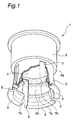
- Fig. 1 is a perspective and partially broken view showing a crown cap according to a first embodiment of the present invention.
- Fig. 2 is a cross sectional view showing the crown cap according to the first embodiment of the present invention, which is placed on a container.
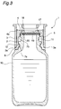
- Fig. 3 is a cross sectional view showing the crown cap according to the first embodiment of the present invention, which is completely fitted to the container.
- Fig. 4 is a cross sectional view showing the crown cap according to a second embodiment of the present invention, which is placed on a container.
- Fig. 5 is a cross sectional view showing the crown cap according to the second embodiment of the present invention, which is completely fitted to the container.
- Fig. 6 is a cross sectional view showing the crown cap according to a third embodiment of the present invention, which is placed on a container.
- Fig. 7 is a cross sectional view showing the crown cap according to the third embodiment of the present invention, which is completely fitted to the container.
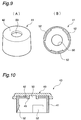
- Fig. 8(A) is a bottom plan view of a closing body used in a fourth embodiment and Fig. 8(B) is a cross sectional view of the closing body taken along the line A-A in Fig. 8(A).
- Fig. 9(A) is a perspective view of the crown-like member according to the fourth embodiment and Fig. 9(B) is a bottom plan view of the crown-like member.
- Fig. 10 is a cross sectional view of a cap unit comprising the closing body shown in Fig. 8 and the crown-like member shown in Fig. 9 which are assembled together.
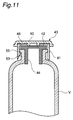
- Fig. 11 is a cross sectional view of a part of a container in the vicinity of the mouth portion thereof, to which the cap unit shown in Fig. 10 is fitted.
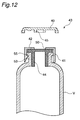
- Fig. 12 is a cross sectional view of the container shown in Fig. 11 from which the closing body is removed.
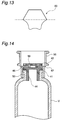
- Fig. 13 is a schematic top plan view showing a closing body as shown in Fig. 8 having a shape other than that shown in Fig. 8.
- Fig. 14 is a cross sectional view of a part of a container in the vicinity of the mouth portion thereof, which is provided with a crown cap according to a fifth embodiment of the present invention.
- Fig. 1 is a perspective and partially broken view, inspected from the bottom, of a crown cap according to the first embodiment of the present invention and Fig. 2 is a vertical section of a container to which the crown cap shown in Fig. 1 is fitted.
- the crown cap 1 comprises two closed-end cylindrical bodies 2, 3 which are united into one body such that they are put one on top of the other while the top board 4 serving as the boundary therebetween is positioned at the center of these cylindrical bodies.
- the lower cylindrical body 2 (positioned on the side of a container 10) constitutes a crown-like member 2 which is fitted to the container 10 in such a manner that it surrounds the periphery of the mouth portion 11 of the container.
- the other cylindrical body 3 (upward positioned) constitutes a close-fastening ring 3 which makes the fitting of the crown-like member 2 to the container solid.
- the close-fastening ring 3 can be fitted to the outer periphery of the crown-like member 2 as will be detailed below by cutting off the ring at the peripheral edge 4a of the top board 4, the edge portion 4a being designed to have a small thickness so as to be easily cut off.
- a plurality of slits 5 are formed on the periphery of the crown-like member 2 at equal spaces.
- circular projected portions 7a, 7b are formed on the inner surface of the crown-like member 2, the lower projected portion 7a is engaged with the mouth portion 11 of the container at the lower end of a flange 12, as will be discussed below in more detail.
- the gasket is engaged with the upper projected portion 7b at the periphery thereof such that the latter member serves as a fixing means for preventing the falling off of the rubber gasket 19 from the top board 4.
- the presence of such a projected portion 7b permits the support of the disc-like rubber gasket 19 to hold it within the crown-like member 2.
- the projected portion 7b for supporting and fixing the rubber gasket 19 does not necessarily have a circular shape and it may be formed in the form of a plurality of projections arranged along a circumference.
- an overhanging portion 6 is formed on the lower peripheral edge of the crown-like member 2.
- a circular opening 17 is formed at the center of the top board 4 and a closing body 18 having a ring serving as a finger-hook is freely removably fitted into the opening 17.
- the edge portion of the closing body 18 and the end surface of the opening 17 are designed to have such shapes as they are engaged with each other and for this reason, the closing body 18 is closely fitted to the opening when the body 18 is pressed into the opening 17.
- a triangular projection 20 is formed on the upper end surface of the mouth portion 11 in order to prevent any slippage of the position of the rubber gasket 19.
- the triangular projection 20 may be partially or completely formed along the circumference the same as in case of the projected portion 7b. This can accordingly prevent any slippage of the rubber gasket 19 in the lateral direction on the mouth portion 11 and also permits the formation of a sufficient thrust to thus further improve the sealing performance thereof.
- the foregoing crown cap 1 is formed from a thermoplastic resin capable of being handled as a combustible material.
- the rubber gasket 19 is naturally a combustible material.
- the container 10 to which the crown cap 1 is fitted is not made of a glass, but is formed from a combustible material such as a thermoplastic resin, the resulting container provided with the crown cap can entirely be handled as a combustible material.
- the crown cap 1 according to this embodiment has the construction detailed above. The functions thereof will now be explained below.
- the plate-like rubber gasket 19 is secured to the top board of the crown-like member 2 prior to the fitting of the crown cap 1 to the container 10.
- the projected portion 7b is formed on the inner surface of the crown-like member 2 and the lower periphery of the rubber gasket 19 is supported by and fixed to the projected portion 7b when the rubber gasket 19 is engaged in the concave portion defined around the inner surface of the crown-like member.
- the projected portion 7b can prevent any removal of the rubber gasket 19 from the crown-like member 2 and accordingly, the rubber gasket 19 never falls off therefrom.
- the container 10 is filled with a drug for injection and then the crown cap 1 to which the rubber gasket 19 is secured as described above is fitted to the container 10 at the mouth portion 11.
- the rubber gasket 19 is made from, for instance, butyl rubber, the surface of which may be coated with a fluoroplastics.
- the rubber gasket 19 provided thereon with a coated film of a fluoroplastics is excellent in resistance to chemical attack. This rubber gasket 19 is preferably used after sufficiently sterilizing by, for instance, heating at 121 °C for 20 minutes.
- the crown-like member 2 When fitting the crown cap 1 to the container 10 according to the manner as described above, the crown-like member 2 can easily be fitted to the outer periphery of the mouth portion 11 because of the presence of slits 5 which are formed on the periphery of the crown-like member 2 at equal spaces. More specifically, the slits 5 are outward expanded to thus enlarge the diameter of the crown-like member 2 and accordingly, the lower projected portion 7a formed on the inner periphery of the crown-like member 2 can descend down to the level below the flange 12 of the mouth portion 11.
- the triangular projection 20 can prevent any slippage of the rubber gasket 19 and the latter is relatively strongly pressed against the mouth portion 11 because of the enagement between the projected portion 7b of the crown-like member 2 and the flange 12 of the mouth portion 11, as shown in Fig. 3.
- the upper close-fastening ring 3 is then downwardly pressed toward the container 10 manually or using an appropriate tool.
- the close-fastening ring 3 is separated from the crown cap at the outer peripheral edge 4a having a small thickness and slides along the outer surface of the crown-like member 2 to thus cover the outer surface thereof. Consequently, the rubber gasket 19 is maintained in a condition pressed along the downward and inward directions.
- the rubber gasket 19 is strongly pressed and thus there are scarcely observed any disengagement of these components or members and/or any slippage in the positions at which they are engaged. Moreover, the rubber gasket 19 is sufficiently compressed and forced down and accordingly, the gasket 19 which usually has a thickness of about 3 mm is deformed to a thickness of about 2.5 mm due to the action of the compression.
- the container 10 to which the crown cap 1 is fitted in a closely fastened condition as described above can be managed and transported while certainly preventing any leakage of a liquid drug from the container.
- the closing body 18 can be separated from the top board 4 by pulling the closing body 18 provided with a finger-hook ring. Accordingly, an opening 17 is formed through the top board 4 and this permits the exposure of the top surface of the underlying rubber gasket 19.
- the rubber gasket 19 is sandwiched between the lower surface of the top board 4 and the triangular projection 20 and also firmly compressed therebetween and therefore, the gasket 19 never falls into the interior.
- the liquid drug kept in the container can be withdrawn from the container 10 by putting a needle of a syringe through the rubber gasket 19 and the opening 17.
- the crown-like member 2 is pushed down and the lower projected portion 7a thereof and the flange 12 of the container 10 are engaged with one another, to fit the cap to the container, while compressing the rubber gasket 19 as an elastic material.
- Such a crown cap may not only be used in containers for keeping injectable liquids, but also effectively used in those for keeping drugs which must be lyophilized. More specifically, the cap of a container for keeping drugs to be lyophilized should be maintained in a half-opened condition immediately before the lyophilization, but such a condition can easily be realized if using the crown cap according to the present invention.
- the projected portion 7b is formed on the inner surface of the crown-like member 2 so that the rubber gasket 19 can be kept in the state wherein the rubber gasket 19 is fitted to the crown-like member 2, but the rubber gasket 19 may, instead, be fixed to the top board 4 through an adhesive layer or by fusion-bonding with heating.
- the rubber gasket 19 is fixed while making use of such a means, it is necessary that the adhesive layer formed by an adhesive or by fusion-bonding with heating is easily broken and the closing body 18 provided with the finger-hook ring is removed therefrom when pulling the closing body 18.
- the rubber gasket 19 may partially be adhered or thermally fusion-bonded in order to improve the release properties.
- notched portions 21 may be formed on the top board of the crown-like member 2 as seen from Figs. 4 and 5. The establishment of such notched portions 21 would permit projection, into the notched portions 21, of a part of the rubber material expanded when the close-fastening ring 3 is put on the outer periphery of the crown-like member 2 and the rubber gasket 19 is then compressed. This in turn permits external release of a part of the stress acting on the rubber gasket 19.
- the liquid drug kept in the container can be taken out by removing the close-fastening ring 3 and then penetrating a needle of a syringe into the container through the rubber gasket 19.
- a flange 3B for reinforcement may be formed on the lower end of the close-fastening ring 3, as shown in Figs. 4 and 5.
- the closing body 18 provided with the finger-hook ring is fitted to the top board 4 of the crown-like member 2, but it is also possible to form an opened portion 14 having a small diameter and to vertically stand a rod-like body 13 through the opened portion 14 as seen from Fig. 6.
- the rod-like body 13 may be pulled out by bending or moving the body back and forth and/or towards the right and left directions.
- the close-fastening force observed when such a crown cap 40 is fitted to the container 10 is sufficiently high like the case shown in Fig. 5.
- the rubber gasket for sealing the passage for drugs is not limited to those having plate-like shapes and may be rubber plug-type 15 ones as shown in Figs. 6 and 7 wherein the gasket has a cylindrical shape provided with a disk-like portion 15a having a large diameter and the lower cylindrical part 15b is push-fitted into the mouth portion 11 of the container 10.
- the closing body 18 provided with the finger-hook ring or the rod-like body 13 is formed as parts separated from the top board 4, but a closing body and the top board 4 may be formed in one-piece.
- the thickness of the portion corresponding to the outer periphery of the opened portion is reduced, the closing body is formed via the thin portion in one-piece and subsequently, the thin portion may be broken by applying a force for pushing down the closing body.
- the close-fastening ring 3 and the crown-like member 2 may not be connected over the entire periphery thereof, but may partially be connected to each other. In such case, the thin outer peripheral edges 4a may scatteringly be distributed on the circumference.
- Figs. 8 to 14 show embodiments wherein the crown caps of the present invention are used for other containers for keeping liquid drugs, i.e., the present invention can likewise be applied to these containers.
- Fig. 8(A) is a bottom plan view of a closing body 40 formed from a thermoplastic resin
- Fig. 8(B) is a cross sectional view of the closing body taken along the line A-A in Fig. 8(A).
- Figs. 9(A) and 9(B) are, respectively, a perspective view and a bottom plan view of the crown-like member 41 to which the closing body 40 as shown in Figs. 8(A) and 8(B) is united by, for instance, the ultrasonic welding.
- Fig. 10 is a cross sectional view of a cap unit 43 which is united to the top board 42 of the crown-like member 41 at an appropriate strength; Fig.
- FIG. 11 is a schematic vertical section showing a condition where the cap unit 43 is fitted to a drug-container V through a rubber plug 44.
- Fig. 12 is a schematic vertical section showing the cap unit 43 fitted to a drug-container V from which a closing body 40 is removed. In such a situation, the drug is taken out of the container using, for instance, a needle of a syringe.
- Fig. 13 is a schematic top plan view showing a closing body having another shape.
- An internal annular protrusion 45 is formed on the closing body 40 near the center of the body and a plurality of projections 46 for welding are formed and arranged on the body along an approximate circumference which surrounds the exterior of the internal annular protrusion 45. Moreover, a peripheral annular protrusion 47 is formed on the outer peripheral edge of the body 40. If a reinforcing projection 48 is further formed, it is formed on or along an approximate circular arc which connects any two neighboring projections 46 for welding or on the region which communicates the annular protrusion 45 and the annular protrusion 47 through any projection 46 for welding.
- Fig. 8(A) three projections 46 for welding are protruded from the lower surface 49 of the closing body 40. It is sufficient for these projections 46 for welding to have a height from the lower surface 49 ranging from 0.3 to 2 mm, preferably 0.5 to 1 mm.
- the shape of the projection 46 for welding is not restricted to any specific one and may be a spot-like, a so-called projected stripe-like, i.e., a mountain chain which extends towards one direction or a ring-like shape. In case of the projected stripe, it may extend in a direction approximately parallel to the circumference or in the radial direction or it may be a combination thereof such as L-shaped.
- the tip thereof to be welded is preferably finer or thinner than the base portion thereof. This accordingly makes the welding easier and the welded portion can easily be peeled off.
- the projection 46 for welding has a spot-like or ring-like shape
- the projection is satisfactorily requested to have a height falling within the range defined above and an average diameter ranging from about 0.3 to 1 mm, preferably about 0.5 to 0.7 mm.
- the projection is satisfactorily requested to have a height falling within the range defined above and a length ranging from about 2 to 5 mm and preferably about 0.3 to 1 mm.
- the length, width or the like of the projection 46 for welding are appropriately selected depending on the characteristic properties of each specific material to be welded.
- Such a projection 46 for welding is welded to the upper surface 42 of the crown-like member 41 made from a resin as shown in Fig. 9 in accordance with the method as will be detailed below.
- the overall tensile strength observed at the welded portion in general ranges from 0.5 to 3 kgf, preferably 0.5 to 2 kgf.
- the projection 46 for welding must satisfy not only the aforementioned requirements, but also those listed below:
- an internal annular projected stripe 45 is positioned near the center of the closing body 40 and that the outer diameter thereof approaches the inner diameter of the central hole 50 of the crown-like member 41, as shown in Fig. 9, as close as possible.
- the purpose of this is to isolate the central hole 50 provided near the center of the upper surface of the crown-like member 41 shown in Fig. 9(A) from the outside to the highest possible level. More specifically, the purpose is to protect the rubber plug 44 shown in Fig. 11 from any contamination.
- projections 46 for welding are protruded from the lower surface 49 of the closing body 40. These projections 46 for welding each has a height, from the lower surface 49 of the closing body 40, of about 0.5 mm and the shape thereof is a trapezoid (truncated cone) which rises from the lower surface 49.
- a reinforcing projected stripes 48 may be formed as described above.
- the reinforcing projected stripes 48 may be provided in the direction such as radial directions from the center of the closing body 40 or those approximately parallel to the circumference of the closing body 40.
- the welded closing body 40 is favorably removed by a method which comprises the step of peeling it along the direction from the periphery to the center thereof. That is, this is effective for avoiding such an unexpected accident that the formation of a crack on the closing body 40 which is exclusively parallel to the circumferential direction, as a result of such a situation that after the projection 46 for welding near the outer periphery of the lower surface of the closing body 40 is peeled off, the projection 46 positioned on the inside thereof cannot be peeled off.
- the embodiment wherein the reinforcing projected stripe 48 is arranged approximately parallel to the circumferential direction is favorale for the process in which the projection 46 for welding is twisted off by rotating the welded closing body 40 in the direction parallel to the circumference. That is, this is effective for avoiding such an unexpected accident that the formation of a crack on the closing body 40 which is exclusively developed in the radial direction, as a result of such a situation that after one of the projections 46 for welding approximately arranged on the same circumference on the closing body 40 is twisted off, another projection 46 arranged on the same circumference cannot be twisted off.
- the number of the projections 46 for welding which stand up from the lower surface of the closing body 40 suitably ranges from 3 to 8. It is in general 3 or 4 or at most 6.
- Fig. 13 shows a closing body 60 having another external shape.
- the upper half of Fig. 13 shows an embodiment of the closing body 60 which has a hexagonal external shape.
- the hexagon is preferably finished so as to have rounded vertices.
- the lower half of Fig. 13 shows an embodiment wherein each side of the closing body 60 caves in towards the center thereof.
- the hexagon is likewise preferably finished so as to have rounded vertices.
- the shape of the foregoing closing body is not limited to circular one and may be polygonal one.
- the crown-like member 41 is a cylindrical body having a lower open end and also having a central hole 50 formed on the center of the top board 42.
- three rib-like projections 52 are formed on the inner periphery thereof at predetermined spaces.
- the foregoing closing body 40 is united with such a crown-like member 41 to give a cap unit 43 by welding the former to the top board 42 of the latter by any proper means for welding.
- the cap unit 43 thus united is fitted to the mouth portion 53 of a drug container V in accordance with the following manner.
- a rubber plug 44 is inserted into the mouth portion 53 of a drug container V.
- the cap unit 43 is put on the mouth portion 53 so as to cover the outer periphery of the portion 53 and subsequently downward pressed strongly.
- the rib-like projections 52 formed on the inner periphery of the crown-like member 41 move down while riding across the flange 55 positioned on the mouth portion of the container V and as a result, the cap unit 43 is fitted to the mouth portion of the container V.
- the closing body 40 can be removed from the crown-like member 41, as shown in Fig. 12, by lightly picking up the body 40 between fingers or by rotating the body 40 in the right and left directions. Under such a condition, the liquid drug can be withdrawn from the container by penetrating a needle of a syringe into the container through the rubber plug 44.
- a close-fastening ring 56 on the top board 42 of the crown-like member 41 as shown in Fig. 14 so that the cap unit 43 is reliably fitted to the drug container V and that the cap unit 43 is never disconnected from the container V even after the lapse of a long time period.
- the close-fastening ring is divisibly communicated to the crown-like member 41 through a thin portion 57.
- the close-fastening ring 56 which is in the condition as shown in Fig. 14 is pushed down to thus cut the thin portion 57.
- the close-fastening ring 56 can closely be fitted to the outer periphery of the crown-like member 41.
- longitudinal slits are formed on the periphery of the crown-like member 41 like the foregoing embodiment.
- Both of the materials for the closing body and the crown-like member must be resins capable of being welded by the high-frequency welding, in particular, ultrasolic welding technique.
- resin(s) used herein means not only crystalline resins, but also all of the polymers including so-called glassy polymers, which are usually regarded as “resins” in the field of molding and which are circulated.
- Resins satisfying this requirement are thermoplastic resins and they also have appropriate melt viscosities. Those having such properties are resins constituted by molecules containing polar elements (electro-negative element) in the molecules. Considering from such a viewpoint, the usual polyolefin polymers are in general undesirable as such materials.
- modified polyolefin polymers are not necessarily excluded.
- these modified polyolefin polymers may optionally contain polar copolymer units to such an extent that they can be welded by the high-frequency welding method, in particular, the ultrasonic welding technique.
- thermoplastic resins each for forming the closing body 40, 58, the crown-like member 41 and the close-fastening ring 56 is one comprising, in its repeating units, at least one electro-negative element selected from nitrogen, oxygen and halogen atoms and halogen atom-containing resins which may be put into practical use are chlorine and/or fluorine atom-containing resins.
- thermoplastic resins examples include polyamide resins (nylons), thermoplastic polyesters, polyvinyl chloride, polyvinylidene chloride, polycarbonates, resins prepared from (meth)acrylic acids or esters or salts thereof, polysulfones, polyisocyanates (polyurethanes), urea resins, polyphenylene ethers (abbreviation: PPE), polyacetals and alicyclic condensed ring-containing resins.
- polyamide resins nylons
- thermoplastic polyesters polyvinyl chloride, polyvinylidene chloride
- polycarbonates resins prepared from (meth)acrylic acids or esters or salts thereof, polysulfones, polyisocyanates (polyurethanes), urea resins, polyphenylene ethers (abbreviation: PPE), polyacetals and alicyclic condensed ring-containing resins.
- PPE polyphenylene ethers
- the foregoing closing body 40, 58, crown-like member 41, close-fastening ring 56 and container V are not necessarily formed from resins of the same kind, but each may be formed from an optimum resin. In practice, however, the closing body 40, 58, the crown-like member 41 and the close-fastening ring 56 are formed from resins of the same kind in most cases.
- the term "resins of the same kind" herein used means resins comprising repeating units common to one another.
- these resins can be melt-bonded to one another.
- these resins must be compatible with one another when they are melted and they must still hold their compatibility with one another even at ordinary temperature.
- Resins different from one another may not easily be melt-bonded together. For instance, widely used polyolefin and polyamide resins which are melt-bonded easily cause delamination when only a slight external force is applied thereto at ordinary temperature.
- thermoplastic resins such as those listed above may be used, but the closing body 40, 58, the crown-like member 41 and the close-fastening ring 56 are preferably formed from the same thermoplastic resin (thermoplastic polymer) and an example of such resin preferably used herein is a polycarbonate (PC), a polyethylene terephthalate (PET) or a polybutylene terephthalate (PBT).
- PC polycarbonate
- PET polyethylene terephthalate
- PBT polybutylene terephthalate
- the resin projection 46 for welding which stands up from the lower surface 49 of the closing body 40 according to the embodiment to the resin top board 42 of the crown-like member 41
- high-frequency welding techniques in particular, ultrasonic welding technique. This is because, this welding means can weld within a quite short time period, for instance, 0.2 to 0.5 sec and make welded at the desirebly small area (i.e., the welding technique permits the spot-welding).
- the welding technique to be selected should be one which permits the welding operation within a time as short as possible without adversely affecting the parts which are not concerned in the welding operation.
- ultrasonic welding techniques are practical.
- electromagnetic waves such as microwaves are also useful means. These welding techniques may appropriately be selected and used depending on the subject to be welded.
- a container V for injections which satisfies the requirements for the Vial No. 1 defined in JIS R3521 was prepared using a tricyclodecene derivative (available from Mitsui Petrochemical Industries, Ltd. under the trade name of APEL 6015) having a condensed polycyclic structure, followed by introducing a drug for test into the resulting container V, fitting a desired rubber plug (which had been sterilized) to the mouth portion of the container while suspending the plug about 4 mm above the mouth portion (half-plugged condition), then lyophilized in a freeze dryer at a temperature of -40°C, complete plugging of the container with the rubber plug and withdrawal thereof from the freeze dryer.
- a tricyclodecene derivative available from Mitsui Petrochemical Industries, Ltd. under the trade name of APEL 6015 having a condensed polycyclic structure
- a cap unit 43 of an integral structure was externally engaged with and fitted to the peripheral edge of the mouth portion of the container V.
- This cap unit 43 of an integral structure was made of a polycarbonate and a closing body 40 was welded and bonded to the upper surface of a crown-like member 41 through three projections 46 for welding which had been formed on the lower surface of the body 40 by supplying ultrasonics (2 X 10 3 Hz; 0.15 sec) to the projections 46 through the upper surface of the body 40 using an ultrasolic welding device (available from BRANSON Company under the trade name of 910IW) so that the tips of the projections 46 were welded to a top board 42 of the crown-like member 41 at a lowest required level of strength.
- an ultrasolic welding device available from BRANSON Company under the trade name of 910IW
- the strength required for the welding and bonding herein means that required for the closing body 40 so as not to cause separation even when spontaneously dropping, from a height of 1m, the vial No. 1 (V) for injection which had been filled with the contents and provided with the fused closing body 40.
- the resulting cap unit 43 did not cause any spontaneous dropping of the closing body 40 during the manual handling thereof. For this reason, there was not observed any contact of the rubber plug portion on the upper surface of the container V and the mouth-peripheral portion thereof with fingers and hands due to unconscious behaviors.
- closing body 40 must be removed prior to the practical use of the injection kept in the vial container V.
- the closing body 40 could safely and rapidly be separated from the cap unit by hand or with a finger without using any particular tool.
- the crown cap according to the present invention ensures a high fastening or tightening force since the close-fastening ring which is usually positioned upward and subsequently closely fastened to the outer periphery of the crown-like member strongly and inwardly presses the crown-like member through the outer periphery of the mouth portion of the container. Moreover, the close fastening ring locks the crown-like member while the former strongly presses the crown-like member in upward and downward directions and accordingly, the opening of the mouth portion of the container can closely be sealed even if a plate-like rubber gasket is used.
- the opening can easily be exposed to thus penetrate, for instance, needles, i.e., the crown cap can conveniently be used.
- the crown cap can be half-plugged and therefore, can be used in lyophilization.
- the crown cap of the present invention may completely be prepared from combustible materials and accordingly, can be disposed as a complete combustible substance without any classification.
Applications Claiming Priority (4)
| Application Number | Priority Date | Filing Date | Title |
|---|---|---|---|
| JP8112005A JPH09278051A (ja) | 1996-04-09 | 1996-04-09 | ロック機構付き冠状蓋 |
| JP112005/96 | 1996-04-09 | ||
| JP11200596 | 1996-04-09 | ||
| PCT/JP1996/002854 WO1997037902A1 (fr) | 1996-04-09 | 1996-10-01 | Couvercle de recipient pour medicaments en forme de couronne |
Publications (3)
| Publication Number | Publication Date |
|---|---|
| EP0837008A1 true EP0837008A1 (fr) | 1998-04-22 |
| EP0837008A4 EP0837008A4 (fr) | 2000-06-07 |
| EP0837008B1 EP0837008B1 (fr) | 2003-01-29 |
Family
ID=14575587
Family Applications (1)
| Application Number | Title | Priority Date | Filing Date |
|---|---|---|---|
| EP96932062A Expired - Lifetime EP0837008B1 (fr) | 1996-04-09 | 1996-10-01 | Couvercle de recipient pour medicaments en forme de couronne |
Country Status (6)
| Country | Link |
|---|---|
| US (1) | US5957314A (fr) |
| EP (1) | EP0837008B1 (fr) |
| JP (1) | JPH09278051A (fr) |
| CA (1) | CA2224166A1 (fr) |
| DE (1) | DE69626019T2 (fr) |
| WO (1) | WO1997037902A1 (fr) |
Cited By (11)
| Publication number | Priority date | Publication date | Assignee | Title |
|---|---|---|---|---|
| FR2787092A1 (fr) * | 1998-12-15 | 2000-06-16 | Lorraine Capsules Metall | Bouchon a capsule verrouillable sur le goulot d'un recipient |
| WO2003013972A1 (fr) * | 2001-08-03 | 2003-02-20 | Helvoet Pharma Belgium N.V. | Bouchon de fermeture destine a des flacons de perfusion ou de transfusion |
| WO2005000703A2 (fr) * | 2003-06-23 | 2005-01-06 | Helvoet Pharma Belgium N.V. | Bouchon de lyophilisation |
| EP1743845A1 (fr) * | 2005-07-14 | 2007-01-17 | GML SERVICE S.r.l. | Fermeture pour flacon pour produits pharmaceutiques ou produits similaires |
| FR2893922A1 (fr) * | 2005-11-30 | 2007-06-01 | Biocorp Rech Et Dev Sa | Dispositif de bouchage pour un recipient et recipient equipe d'un tel dispositif |
| WO2007063218A1 (fr) * | 2005-11-30 | 2007-06-07 | Biocorp Recherche Et Developpement | Dispositif de bouchage pour un recipient et recipient equipe d'un tel dispositif |
| FR2900131A1 (fr) * | 2006-04-20 | 2007-10-26 | Biocorp Rech Et Dev Sa | Dispositif de bouchage pour un recipient et recipient equipe d'un tel dispositif |
| EP1870347A2 (fr) * | 2006-06-19 | 2007-12-26 | Grifols, S.A. | Butoir pour flacons de produits stériles et utilisation de ce butoir pour un remplissage mesuré stérile |
| FR2904988A1 (fr) * | 2006-08-16 | 2008-02-22 | Mann & Hummel Gmbh | Dispositif d'encliquetage de securite d'un couvercle sur un corps d'accessoire |
| FR2908396A1 (fr) * | 2006-11-10 | 2008-05-16 | Biocorp Rech Et Dev Sa | Dispositif de bouchage, recipient equipe d'un tel dispositif et procede de fabrication d'un tel dispositif |
| CN101952179B (zh) * | 2008-02-11 | 2012-02-22 | 生物研究与发展公司 | 具有压帽的塞盖装置以及装配有该装置的容器 |
Families Citing this family (47)
| Publication number | Priority date | Publication date | Assignee | Title |
|---|---|---|---|---|
| EP0989065B1 (fr) * | 1996-11-25 | 2002-08-14 | Diseno Industrial Mago, S.L. | Bouchon a fermeture hermetique |
| EP1044135B1 (fr) * | 1998-07-14 | 2002-10-09 | Amersham Health AS | Emballage |
| US6907679B2 (en) * | 1998-11-12 | 2005-06-21 | Qlt Usa, Inc. | Method for lyophilizing an active agent |
| US6722054B2 (en) | 1998-11-12 | 2004-04-20 | Atrix Laboratories, Inc. | Process and delivery container for lyophilizing active agent |
| DE19938131B4 (de) * | 1999-08-16 | 2006-08-31 | Ti Automotive Technology Center Gmbh | Kraftstoffbehälter |
| US6659296B2 (en) * | 2000-01-26 | 2003-12-09 | Amersham Health As | Cap for container |
| US20020150709A1 (en) * | 2001-04-16 | 2002-10-17 | Hetzler Kevin George | Method of fusing a component to a medical storage or transfer device and container assembly |
| GB0129176D0 (en) * | 2001-12-06 | 2002-01-23 | Dca Design Int Ltd | Improvements in and realting to a medicament cartridge assembly |
| DE602004016501D1 (de) * | 2003-06-03 | 2008-10-23 | Taisei Kako Co | Kappe für behälter |
| ES2608284T3 (es) | 2006-05-25 | 2017-04-07 | Bayer Healthcare Llc | Dispositivo de reconstitución |
| KR100757795B1 (ko) * | 2006-06-21 | 2007-09-11 | 채동석 | 마개 및 이 마개가 구비된 용기 |
| FR2912384B1 (fr) * | 2007-02-09 | 2009-04-10 | Biocorp Rech Et Dev Sa | Dispositif de bouchage pour un recipient, recipient equipe d'un tel dispositif et procede de fermeture d'un lot de tel recipient |
| EP2377504B1 (fr) * | 2009-01-06 | 2018-10-31 | Fujimori Kogyo Co., Ltd. | Orifice de versage, procédé pour sa production et récipient à liquide doté de l'orifice de versage |
| GB0901185D0 (en) * | 2009-01-26 | 2009-03-11 | Crew Mouldings Ltd | A plastic closure for a container |
| KR101121860B1 (ko) * | 2009-06-22 | 2012-03-20 | 채동석 | 마개 및 이 마개를 갖는 용기 |
| FR2950035B1 (fr) | 2009-09-15 | 2011-09-02 | Raymond A & Cie | Coiffe de verrouillage pour recipient a col |
| FR2950865B1 (fr) | 2009-10-01 | 2011-10-28 | Raymond A & Cie | Coiffe de verrouillage pour recipient a col avec une capsule a pattes de fixation |
| FR2967655B1 (fr) * | 2010-11-24 | 2014-03-14 | Biocorp Rech Et Dev | Dispositif de bouchage d'un recipient, recipient equipe d'un tel dispositif et procede de fermeture d'un lot de tels recipients |
| GB2485254C (en) * | 2011-08-22 | 2013-12-25 | Eulysis Uk Ltd | A container having a recessed closure for drying and storing one or more active agents |
| FR2986782B1 (fr) | 2012-02-13 | 2014-03-07 | Raymond A & Cie | Dispositif de verrouillage de bouchon sur recipient a collerette, recipient a collerette obture par bouchon pourvu d'un tel dispositif de verrouillage |
| KR101396617B1 (ko) * | 2014-01-07 | 2014-05-16 | 이수호 | 캔 덮개의 4중 밀폐구조 |
| JP6319788B2 (ja) * | 2014-02-14 | 2018-05-09 | 日本クロージャー株式会社 | 易開封型打栓式キャップ |
| CA2949219C (fr) * | 2014-06-18 | 2022-07-05 | Antonio Mutterle | Procede de fermeture hermetique d'une bouteille et bouteille a fermeture hermetique correspondante |
| AR098591A1 (es) * | 2014-12-02 | 2016-06-01 | Juan Rosson Eduardo | Cierre de seguridad de giro corto para recipientes y botella para dicho cierre |
| ES2566202B1 (es) * | 2015-10-30 | 2017-01-24 | Enotop Closures Sl | Conjunto de tapón y de anillo de retención para tiraje de vinos espumosos |
| AR107541A1 (es) | 2016-02-05 | 2018-05-09 | Tolmar Therapeutics Inc | Placa de recubrimiento ventilada para un conjunto de jeringas |
| US10307542B2 (en) * | 2016-05-20 | 2019-06-04 | David I. Levenson | Handle for a medicinal pen |
| US11097071B1 (en) | 2016-12-14 | 2021-08-24 | International Medical Industries Inc. | Tamper evident assembly |
| US11541180B1 (en) | 2017-12-21 | 2023-01-03 | Patrick Vitello | Closure assembly having a snap-fit construction |
| CN111511651B (zh) * | 2017-12-27 | 2022-10-25 | 美国圣戈班性能塑料公司 | 盖组件 |
| JP6848126B2 (ja) * | 2018-01-19 | 2021-03-24 | ウェスト ファーマスーティカル サービシーズ ドイチェラント ゲーエムベーハー ウント カンパニー カーゲー | 閉塞装置 |
| US11278681B1 (en) | 2018-02-20 | 2022-03-22 | Robert Banik | Tamper evident adaptor closure |
| US11413406B1 (en) | 2018-03-05 | 2022-08-16 | Jonathan J. Vitello | Tamper evident assembly |
| USD908916S1 (en) | 2018-06-19 | 2021-01-26 | Tolmar Therapeutics, Inc. | Syringe restrictor plate |
| US11857751B1 (en) | 2018-07-02 | 2024-01-02 | International Medical Industries Inc. | Assembly for a medical connector |
| US11779520B1 (en) | 2018-07-02 | 2023-10-10 | Patrick Vitello | Closure for a medical dispenser including a one-piece tip cap |
| US11793987B1 (en) | 2018-07-02 | 2023-10-24 | Patrick Vitello | Flex tec closure assembly for a medical dispenser |
| US11690994B1 (en) | 2018-07-13 | 2023-07-04 | Robert Banik | Modular medical connector |
| US11426328B1 (en) | 2018-08-31 | 2022-08-30 | Alexander Ollmann | Closure for a medical container |
| US11471610B1 (en) | 2018-10-18 | 2022-10-18 | Robert Banik | Asymmetrical closure for a medical device |
| USD948713S1 (en) | 2019-09-03 | 2022-04-12 | International Medical Industries, Inc. | Asymmetrical self righting tip cap |
| US11911339B1 (en) | 2019-08-15 | 2024-02-27 | Peter Lehel | Universal additive port cap |
| US11697527B1 (en) * | 2019-09-11 | 2023-07-11 | Logan Hendren | Tamper evident closure assembly |
| US11357588B1 (en) | 2019-11-25 | 2022-06-14 | Patrick Vitello | Needle packaging and disposal assembly |
| US11904149B1 (en) | 2020-02-18 | 2024-02-20 | Jonathan Vitello | Oral tamper evident closure with retained indicator |
| US11523970B1 (en) | 2020-08-28 | 2022-12-13 | Jonathan Vitello | Tamper evident shield |
| US11872187B1 (en) | 2020-12-28 | 2024-01-16 | Jonathan Vitello | Tamper evident seal for a vial cover |
Citations (7)
| Publication number | Priority date | Publication date | Assignee | Title |
|---|---|---|---|---|
| NL8700799A (nl) * | 1987-04-06 | 1988-11-01 | Duphar Int Res | Sluitdop met klemring. |
| US5085332A (en) * | 1991-04-11 | 1992-02-04 | Gettig Technologies, Inc. | Closure assembly |
| US5303835A (en) * | 1992-06-24 | 1994-04-19 | Habley Medical Technology Corporation | Lyophilization cap and method |
| US5314084A (en) * | 1992-08-21 | 1994-05-24 | The West Company, Incorporated | Two piece all plastic seal |
| US5379908A (en) * | 1991-10-28 | 1995-01-10 | F.E.S. Kunststoff Gmbh | Plastic closure cap, in particular for glass containers |
| US5455180A (en) * | 1994-03-24 | 1995-10-03 | Innovative Molding, Inc. | Container closure of medical tests |
| EP0747293A1 (fr) * | 1995-06-07 | 1996-12-11 | J.G. Finneran Associates, Inc. | Flacon et fermeture sertie sur le flacon |
Family Cites Families (9)
| Publication number | Priority date | Publication date | Assignee | Title |
|---|---|---|---|---|
| US3888377A (en) * | 1973-05-30 | 1975-06-10 | Reinhard Stadler | Closure cap for an infusion flask |
| JPS589881Y2 (ja) * | 1978-02-08 | 1983-02-23 | 吉田工業株式会社 | 封緘中栓 |
| US4254884A (en) * | 1978-10-20 | 1981-03-10 | Toppan Printing Co., Ltd. | Plug body for a container |
| JPH0454926Y2 (fr) * | 1986-11-19 | 1992-12-24 | ||
| JPS6388963U (fr) * | 1986-11-27 | 1988-06-09 | ||
| JPH01161455U (fr) * | 1988-04-27 | 1989-11-09 | ||
| US5269429A (en) * | 1990-05-15 | 1993-12-14 | Robert Finke Gmbh & Co. Kg | Closure cap for infusion or transfusion bottles |
| DE4228090C2 (de) * | 1992-08-24 | 1995-01-05 | Pohl Gmbh & Co Kg | Verschluß für eine Flasche |
| KR0119874Y1 (ko) * | 1993-03-02 | 1998-06-01 | 이용학 | 주사제용 합성수지재 밀봉캡 |
-
1996
- 1996-04-09 JP JP8112005A patent/JPH09278051A/ja active Pending
- 1996-10-01 EP EP96932062A patent/EP0837008B1/fr not_active Expired - Lifetime
- 1996-10-01 DE DE69626019T patent/DE69626019T2/de not_active Expired - Fee Related
- 1996-10-01 WO PCT/JP1996/002854 patent/WO1997037902A1/fr active IP Right Grant
- 1996-10-01 US US08/973,423 patent/US5957314A/en not_active Expired - Fee Related
- 1996-10-01 CA CA002224166A patent/CA2224166A1/fr not_active Abandoned
Patent Citations (8)
| Publication number | Priority date | Publication date | Assignee | Title |
|---|---|---|---|---|
| NL8700799A (nl) * | 1987-04-06 | 1988-11-01 | Duphar Int Res | Sluitdop met klemring. |
| US5085332A (en) * | 1991-04-11 | 1992-02-04 | Gettig Technologies, Inc. | Closure assembly |
| US5085332B1 (en) * | 1991-04-11 | 1994-04-05 | Gettig Technologies Inc | Closure assembly |
| US5379908A (en) * | 1991-10-28 | 1995-01-10 | F.E.S. Kunststoff Gmbh | Plastic closure cap, in particular for glass containers |
| US5303835A (en) * | 1992-06-24 | 1994-04-19 | Habley Medical Technology Corporation | Lyophilization cap and method |
| US5314084A (en) * | 1992-08-21 | 1994-05-24 | The West Company, Incorporated | Two piece all plastic seal |
| US5455180A (en) * | 1994-03-24 | 1995-10-03 | Innovative Molding, Inc. | Container closure of medical tests |
| EP0747293A1 (fr) * | 1995-06-07 | 1996-12-11 | J.G. Finneran Associates, Inc. | Flacon et fermeture sertie sur le flacon |
Non-Patent Citations (1)
| Title |
|---|
| See also references of WO9737902A1 * |
Cited By (14)
| Publication number | Priority date | Publication date | Assignee | Title |
|---|---|---|---|---|
| FR2787092A1 (fr) * | 1998-12-15 | 2000-06-16 | Lorraine Capsules Metall | Bouchon a capsule verrouillable sur le goulot d'un recipient |
| WO2003013972A1 (fr) * | 2001-08-03 | 2003-02-20 | Helvoet Pharma Belgium N.V. | Bouchon de fermeture destine a des flacons de perfusion ou de transfusion |
| WO2005000703A2 (fr) * | 2003-06-23 | 2005-01-06 | Helvoet Pharma Belgium N.V. | Bouchon de lyophilisation |
| WO2005000703A3 (fr) * | 2003-06-23 | 2005-04-07 | Helvoet Pharma | Bouchon de lyophilisation |
| EP1743845A1 (fr) * | 2005-07-14 | 2007-01-17 | GML SERVICE S.r.l. | Fermeture pour flacon pour produits pharmaceutiques ou produits similaires |
| WO2007063218A1 (fr) * | 2005-11-30 | 2007-06-07 | Biocorp Recherche Et Developpement | Dispositif de bouchage pour un recipient et recipient equipe d'un tel dispositif |
| FR2893922A1 (fr) * | 2005-11-30 | 2007-06-01 | Biocorp Rech Et Dev Sa | Dispositif de bouchage pour un recipient et recipient equipe d'un tel dispositif |
| US8225949B2 (en) | 2005-11-30 | 2012-07-24 | Biocorp Recherche Et Developpement | Plug device for a container and container provided with one such device |
| FR2900131A1 (fr) * | 2006-04-20 | 2007-10-26 | Biocorp Rech Et Dev Sa | Dispositif de bouchage pour un recipient et recipient equipe d'un tel dispositif |
| EP1870347A2 (fr) * | 2006-06-19 | 2007-12-26 | Grifols, S.A. | Butoir pour flacons de produits stériles et utilisation de ce butoir pour un remplissage mesuré stérile |
| EP1870347A3 (fr) * | 2006-06-19 | 2009-09-30 | Grifols, S.A. | Butoir pour flacons de produits stériles et utilisation de ce butoir pour un remplissage mesuré stérile |
| FR2904988A1 (fr) * | 2006-08-16 | 2008-02-22 | Mann & Hummel Gmbh | Dispositif d'encliquetage de securite d'un couvercle sur un corps d'accessoire |
| FR2908396A1 (fr) * | 2006-11-10 | 2008-05-16 | Biocorp Rech Et Dev Sa | Dispositif de bouchage, recipient equipe d'un tel dispositif et procede de fabrication d'un tel dispositif |
| CN101952179B (zh) * | 2008-02-11 | 2012-02-22 | 生物研究与发展公司 | 具有压帽的塞盖装置以及装配有该装置的容器 |
Also Published As
| Publication number | Publication date |
|---|---|
| DE69626019T2 (de) | 2003-10-02 |
| US5957314A (en) | 1999-09-28 |
| WO1997037902A1 (fr) | 1997-10-16 |
| DE69626019D1 (de) | 2003-03-06 |
| JPH09278051A (ja) | 1997-10-28 |
| EP0837008A4 (fr) | 2000-06-07 |
| CA2224166A1 (fr) | 1997-10-16 |
| EP0837008B1 (fr) | 2003-01-29 |
Similar Documents
| Publication | Publication Date | Title |
|---|---|---|
| EP0837008B1 (fr) | Couvercle de recipient pour medicaments en forme de couronne | |
| US5433716A (en) | Safety closing device for biological liquid containers | |
| US7703626B2 (en) | Composite closures for containers | |
| US5904259A (en) | Protective tamper-evident label and bottle cap | |
| EP1659071B1 (fr) | Fermeture constituée de deux parties pour un récipient | |
| JP2660480B2 (ja) | プラスチック製繰り返し使用容器、その製造方法および修復方法 | |
| KR20010092417A (ko) | 용기 조립체 및 용기 조립체용 바닥 캡 | |
| US5551608A (en) | Closure assembly with tabbed liner | |
| CA1107241A (fr) | Fermeture etanche pour contenant plastique, avec fermeture externe protectrice d'interverrouillage | |
| US4523689A (en) | Reusable tamper-proof container | |
| US5219083A (en) | Stopper for reduction of particulate matter | |
| US4961450A (en) | Toner cartridge | |
| WO2020163714A1 (fr) | Fermeture de distribution pour un récipient | |
| CA2091020C (fr) | Pellicule d'obturation limitant la production de particules | |
| JP3633666B2 (ja) | 樹脂製上蓋、それが緊締キャップ頂面に適度に接合された樹脂製の密封兼緊締ユニット及び密封兼緊締ユニットの製造方法 | |
| JP3113595B2 (ja) | 中栓、キャップ並びに中栓とキャップの組合せ体 | |
| CA1142146A (fr) | Systeme debiteur a cartouche et piston concourant | |
| US6908001B2 (en) | Narrow pull tab | |
| US6240708B1 (en) | Method of packaging pharmaceuticals | |
| CA1052732A (fr) | Contenant sterile refermable | |
| AU2005209675A1 (en) | Two-part closure for a container | |
| JP4616485B2 (ja) | 合成樹脂製蓋及び液体供給装置 | |
| GB2218077A (en) | Tamper-evident package and closure means | |
| AU6655500A (en) | Plastic closure for vials and other medical containers | |
| JP2006224996A (ja) | ライナー付プラスチックキャップ |
Legal Events
| Date | Code | Title | Description |
|---|---|---|---|
| PUAI | Public reference made under article 153(3) epc to a published international application that has entered the european phase |
Free format text: ORIGINAL CODE: 0009012 |
|
| AK | Designated contracting states |
Kind code of ref document: A1 Designated state(s): DE FR GB IT |
|
| 17P | Request for examination filed |
Effective date: 19980408 |
|
| A4 | Supplementary search report drawn up and despatched |
Effective date: 20000420 |
|
| AK | Designated contracting states |
Kind code of ref document: A4 Designated state(s): DE FR GB IT |
|
| 17Q | First examination report despatched |
Effective date: 20010313 |
|
| RIC1 | Information provided on ipc code assigned before grant |
Free format text: 7B 65D 51/00 A |
|
| GRAG | Despatch of communication of intention to grant |
Free format text: ORIGINAL CODE: EPIDOS AGRA |
|
| GRAG | Despatch of communication of intention to grant |
Free format text: ORIGINAL CODE: EPIDOS AGRA |
|
| GRAH | Despatch of communication of intention to grant a patent |
Free format text: ORIGINAL CODE: EPIDOS IGRA |
|
| GRAH | Despatch of communication of intention to grant a patent |
Free format text: ORIGINAL CODE: EPIDOS IGRA |
|
| GRAA | (expected) grant |
Free format text: ORIGINAL CODE: 0009210 |
|
| AK | Designated contracting states |
Designated state(s): DE FR GB IT |
|
| REG | Reference to a national code |
Ref country code: GB Ref legal event code: FG4D |
|
| REF | Corresponds to: |
Ref document number: 69626019 Country of ref document: DE Date of ref document: 20030306 Kind code of ref document: P |
|
| ET | Fr: translation filed | ||
| PLBE | No opposition filed within time limit |
Free format text: ORIGINAL CODE: 0009261 |
|
| STAA | Information on the status of an ep patent application or granted ep patent |
Free format text: STATUS: NO OPPOSITION FILED WITHIN TIME LIMIT |
|
| 26N | No opposition filed |
Effective date: 20031030 |
|
| PGFP | Annual fee paid to national office [announced via postgrant information from national office to epo] |
Ref country code: FR Payment date: 20050930 Year of fee payment: 10 |
|
| PG25 | Lapsed in a contracting state [announced via postgrant information from national office to epo] |
Ref country code: IT Free format text: LAPSE BECAUSE OF NON-PAYMENT OF DUE FEES Effective date: 20051001 |
|
| PGFP | Annual fee paid to national office [announced via postgrant information from national office to epo] |
Ref country code: DE Payment date: 20051024 Year of fee payment: 10 |
|
| PGFP | Annual fee paid to national office [announced via postgrant information from national office to epo] |
Ref country code: GB Payment date: 20051025 Year of fee payment: 10 |
|
| PG25 | Lapsed in a contracting state [announced via postgrant information from national office to epo] |
Ref country code: DE Free format text: LAPSE BECAUSE OF NON-PAYMENT OF DUE FEES Effective date: 20070501 |
|
| GBPC | Gb: european patent ceased through non-payment of renewal fee |
Effective date: 20061001 |
|
| REG | Reference to a national code |
Ref country code: FR Ref legal event code: ST Effective date: 20070629 |
|
| PG25 | Lapsed in a contracting state [announced via postgrant information from national office to epo] |
Ref country code: GB Free format text: LAPSE BECAUSE OF NON-PAYMENT OF DUE FEES Effective date: 20061001 |
|
| PG25 | Lapsed in a contracting state [announced via postgrant information from national office to epo] |
Ref country code: FR Free format text: LAPSE BECAUSE OF NON-PAYMENT OF DUE FEES Effective date: 20061031 |