EP0836993B1 - Verfahren und Vorrichtung zum Umhüllen von Zigarettenpackungen mit Kartonzuschnitten - Google Patents
Verfahren und Vorrichtung zum Umhüllen von Zigarettenpackungen mit Kartonzuschnitten Download PDFInfo
- Publication number
- EP0836993B1 EP0836993B1 EP97830450A EP97830450A EP0836993B1 EP 0836993 B1 EP0836993 B1 EP 0836993B1 EP 97830450 A EP97830450 A EP 97830450A EP 97830450 A EP97830450 A EP 97830450A EP 0836993 B1 EP0836993 B1 EP 0836993B1
- Authority
- EP
- European Patent Office
- Prior art keywords
- flap
- movement
- face
- blank
- group
- Prior art date
- Legal status (The legal status is an assumption and is not a legal conclusion. Google has not performed a legal analysis and makes no representation as to the accuracy of the status listed.)
- Expired - Lifetime
Links
- 238000000034 method Methods 0.000 title claims description 18
- 235000019504 cigarettes Nutrition 0.000 title claims description 13
- 238000005452 bending Methods 0.000 claims description 9
- 230000001747 exhibiting effect Effects 0.000 claims 1
- 230000015572 biosynthetic process Effects 0.000 description 1
- 230000000977 initiatory effect Effects 0.000 description 1
- 238000004519 manufacturing process Methods 0.000 description 1
- 230000000284 resting effect Effects 0.000 description 1
Images


Classifications
-
- B—PERFORMING OPERATIONS; TRANSPORTING
- B65—CONVEYING; PACKING; STORING; HANDLING THIN OR FILAMENTARY MATERIAL
- B65B—MACHINES, APPARATUS OR DEVICES FOR, OR METHODS OF, PACKAGING ARTICLES OR MATERIALS; UNPACKING
- B65B11/00—Wrapping, e.g. partially or wholly enclosing, articles or quantities of material, in strips, sheets or blanks, of flexible material
- B65B11/004—Wrapping, e.g. partially or wholly enclosing, articles or quantities of material, in strips, sheets or blanks, of flexible material in blanks, e.g. sheets precut and creased for folding
-
- B—PERFORMING OPERATIONS; TRANSPORTING
- B65—CONVEYING; PACKING; STORING; HANDLING THIN OR FILAMENTARY MATERIAL
- B65B—MACHINES, APPARATUS OR DEVICES FOR, OR METHODS OF, PACKAGING ARTICLES OR MATERIALS; UNPACKING
- B65B11/00—Wrapping, e.g. partially or wholly enclosing, articles or quantities of material, in strips, sheets or blanks, of flexible material
- B65B11/06—Wrapping articles, or quantities of material, by conveying wrapper and contents in common defined paths
- B65B11/08—Wrapping articles, or quantities of material, by conveying wrapper and contents in common defined paths in a single straight path
- B65B11/10—Wrapping articles, or quantities of material, by conveying wrapper and contents in common defined paths in a single straight path to fold the wrappers in tubular form about contents
- B65B11/12—Wrapping articles, or quantities of material, by conveying wrapper and contents in common defined paths in a single straight path to fold the wrappers in tubular form about contents and then to form closing folds of similar form at opposite ends of the tube
-
- B—PERFORMING OPERATIONS; TRANSPORTING
- B65—CONVEYING; PACKING; STORING; HANDLING THIN OR FILAMENTARY MATERIAL
- B65B—MACHINES, APPARATUS OR DEVICES FOR, OR METHODS OF, PACKAGING ARTICLES OR MATERIALS; UNPACKING
- B65B49/00—Devices for folding or bending wrappers around contents
- B65B49/12—Rotary folders
Definitions
- the present invention relates to a method and a unit for carton-wrapping packets of cigarettes.
- packets of cigarettes are wrapped in carton type packs by methods involving the use of flat die-cut cardboard blanks, wherein the single blank is folded along precreased lines to create a wrapper for a relative group of packets appearing substantially parallelepiped in shape and constituting the contents of the carton.
- groups of packets advancing in succession are caused to cross a feed line carrying the blanks, in such a way that each blank is invested by and bent into a "U" configuration around a relative group, enveloping three faces of the parallelepiped and leaving the other three exposed; in this situation the blank continues to project beyond the dimensional compass of the group, affording at least two flaps on three sides that are destined ultimately to be bent through 90° and flattened against the three exposed faces.
- this document teaches the use of folder units, one to each of the faces in question, rendered capable of alternating movement toward and away from a folding station and equipped with folder elements by which the flaps are engaged in contact and thereupon bent to a right angle.
- the operation of folding the flaps down over each of the exposed faces takes place with the blank and the corresponding group of packets held at a standstill in the folding station, and occurs as the result of each folder unit being caused to make a forward stroke toward the station in a direction parallel to the relative exposed face.
- Significant mechanical complications accompany the use of the method outlined above in cartoning machines, with regard especially to the alternating movement of the folder units.
- the object of the present invention is to provide a method for carton-wrapping packets of cigarettes that will be unaffected by the drawbacks described above.
- the object of the present invention is to provide a method for carton-wrapping packets of cigarettes in which the advantages of simplicity and economy are maximized as far as possible.
- An additional object of the invention is to provide a method for carton-wrapping packets of cigarettes in which the wrapping materials utilized are subjected to minimal stresses, and moreover in which the mechanical stresses applied to the fold-making components are reduced to a minimum, as also is the noise generated by these same components.
- the stated object is realized according to the present invention in a method for carton-wrapping packets of cigarettes that comprises the steps of: advancing a group of packets substantially parallelepiped in shape along a predetermined direction of movement and across a feed line conveying die-cut blanks, in such a way that each blank is engaged by a relative group, folded to a U profile and caused to envelop three faces of the group, namely a first transverse face positioned forwardmost in the direction of movement and two faces disposed parallel both with one another and with the direction of movement; folding the blank further about the group in such a manner as to envelop a fourth face remote from the first face, thereby producing a closed configuration in which the blank projects beyond the two remaining end faces presented by the two opposite ends of the parallelepiped, affording at least one first flap and one second flap disposed orthogonally to each of the selfsame end faces; and bending the first and second flaps through a right angle and into contact with the respective end faces to complete the wrapping operation, characterized in that the step
- the folder head is rotatable about an axis disposed perpendicular to the direction of movement followed by the groups of-packets.
- the present invention relates also to a unit for carton-wrapping packets of cigarettes.
- a unit for carton-wrapping packets of cigarettes comprises a feed line conveying die-cut blanks; pushing means by which groups of packets substantially parallelepiped in shape are caused to advance along a predetermined direction of movement and across the feed line in such a way that each blank is engaged by a respective group, folded to a U profile and caused to envelop three faces of the group, -namely a first transverse face positioned forwardmost in the direction of movement and two faces disposed parallel with one another and with the direction of movement; first folding means by which the blank is closed around the group in such a way as to envelop a fourth face remote from the first face, producing a configuration in which the blank projects beyond the two remaining faces presented by the two opposite ends of the parallelepiped, affording at least one first flap and one second flap disposed orthogonally to each of the selfsame end faces; also second folding means by which the first and second flaps are engaged, bent to a right angle and flattened against the relative end face to complete the wrapping operation, characterized in
- the folder head rotates about an axis disposed perpendicular to the direction of movement followed by the groups of packets.
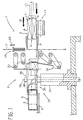
- 1 denotes a cartoning machine, in its entirety, incorporating a unit 2 of which the function is to assemble cartons 3 of packets 4 containing cigarettes.
- the packets 4 are supplied to the unit 2 as groups 5 of substantially parallelepiped shape, each comprising a plurality of individual packets 4 arranged alongside and on top of one another ready to be enveloped in a single wrapper 6 fashioned from a precreased die-cut blank 7 of sheet material.
- Each group 5 of packets 4 has a longitudinal axis 8 and presents two larger side faces 9 and 10, also two smaller side faces 11 and 12, and two end faces 13.
- the unit 2 comprises a conveyor 14 along which the packets 4 advance in continuous succession, ordered in stacks 4' two-high, following a direction 15 parallel to the axis 8 of the group 5 which carries them toward a wrapping station 16.
- the wrapping station 16 is equipped with a push rod 17 capable of reciprocating movement in a direction 18 transverse to the conveying direction 15.
- the rod 17 presents a pushing surface 17' of which the length, measured along the conveying direction 15, is such as will enable it to impinge during each active stroke on a number of stacks 4' equivalent to the number (five, in fig 2) making up a single group 5.
- a group 5 of packets 4 is made to advance with the smaller face denoted 11 forwardmost and to cross a feed line 19, along which the blanks 7 are carried in a direction 20 orthogonal to the directions 18 and 15 followed by the packets 4, proceeding thereafter with the downwardly directed larger face 10 resting slidably on a plate P located immediately beyond the selfsame feed line 19 in the pushing direction 18.
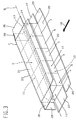
- each group 5 directed across the feed line 19 becomes associated with a respective blank 7 which is then folded into a U shape in such a way as to envelop the group 5 in part. More exactly, two side panels 21 and 22 of the blank 7 are flattened against the larger side faces 9 and 10 of the group 5, whilst one intermediate panel 23 of the blank 7 is flattened against the leading smaller side face 11.
- the side panels 21 and 22 are extended by way of the two edges remote from the intermediate panel 23 into longitudinal panels 24 and 25 projecting outwards from the remaining side face 12.
- the blank 7 affords two pairs of flaps 26 and 27 associated with the side panels 21 and 22 via the edges lying in the two planes occupied by the respective end faces 13, a further pair of flaps 28 projecting externally from each end of the intermediate panel 23, and finally a pair of flaps 29 projecting externally from each end of the longitudinal panel denoted 25.
- the group 5 advances along the plate P in the pushing direction 18, still driven by the rod 17, toward a limit position that coincides with a folding station denoted 30; here the assembled parts 5 and 7 are brought to a standstill so that the process of folding up the wrapper 6 to form a relative carton 3 is completed.
- the unit 2 comprises a top folder 33 and a bottom folder 34, both of conventional guillotine type embodiment, positioned at the folding station 30 and capable of alternating movement in a direction substantially perpendicular to the plate P, of which the function is to close up each successive blank 7 into a tube via a familiar process whereby the two projecting panels 24 and 25 are engaged and bent through a right angle into contact with the relative face 12 of the group 5.
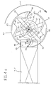
- Each head 35 is designed to interact with the respective flaps 26, 27, 28 and 29 of the single blank 7 in such a way that these are flattened against the two corresponding end faces 13 of the group 5 in a succession of folds, shortly to be described, with the flap denoted 27 sandwiched between that denoted 26 and the remaining two 28 and 29.
- each folder head 35 is compassed peripherally by a cylindrical surface 36 and comprises a body 37 keyed to the output shaft 38 of a motor (not indicated) by which the head 35 is set in substantially continuous rotation about an axis 39 disposed orthogonal to the plate P and to the pushing direction 18 and parallel with the direction 20 along which the blanks 7 approach the folding station 30.
- Each head 35 is caused to rotate about its own axis 39 in a direction F such that in operation, the mutually opposed portions of the two cylindrical surfaces 36 revolve convergently with the pushing direction 18.
- the single head 35 presents two diametrally opposed radial arms 40 supported by and connected to a first end of the relative body 37, also two radial arms 41 connected to a second end of the body 37 and likewise diametrally opposed, in positions offset from those of the first arms 40.
- each first radial arm 40 combines with a respective appendage 42 of the body 37 to support a blade 43 presenting the appearance of a substantially spherically contoured cap or spoon disposed with the concave side directed toward a respective second radial arm 41 and terminating forwardmost, relative to the direction of movement F, in a forcing edge 44.
- the spherically contoured outer surface of the blade 43 merges on the one hand with one end of a prong disposed along the cylindrical surface 36 in the manner of a terminal appendage or portion 45, extending rearwards (relative to the direction of movement F) from the blade 43, and on the other with an appendage or edge 46 of hook like profile extending forward from the blade 43.
- each second radial arm 41 supports a blade 47 presenting the appearance of a substantially spherically contoured cap or spoon disposed with the concave side directed toward a respective first radial arm 40 and terminating forwardmost, relative to the direction of movement F, in a forcing edge 48.
- the spherically contoured outer surface of each such blade 47 merges with one end of a prong disposed along the cylindrical surface 36 in the manner of a terminal appendage or portion 49, extending rearwards (in relation to the direction of movement F indicated in fig 2) from the blade 47.
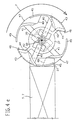
- each of the flaps denoted 28 will be engaged by the terminal portion 49 of a blade 47 associated with the respective head 35, bent through 90° in the direction opposite to the pushing direction 18 and flattened thus against the corresponding end face 13.
- the rotation of the two heads 35 will be timed in relation to the movement of the push rod 17 during the operating cycle of the unit 2 in such a manner that on the arrival of each assembled group 5 and blank 7 at the folding station 30, the terminal portion 49 of one of the blades 47 afforded by each head 35 will always be positioned to intercept the relative flap 28.
- the top and bottom folders 33 and 34 come into operation, impinging respectively on the projecting panels 24 and 25 in conventional manner and causing the blank 7 to close around the group 5 in a tubular configuration with the two panels 24 and 25 now flattened over the hitherto exposed side face 12 and three flaps 26, 27 and 29 still projecting at each end; in particular, the two larger flaps 26 and 27 are disposed mutually parallel, orthogonal to the axis 39 of the relative folder head 35 and to the end face 13, whilst the remaining flap 29 is disposed between the two larger flaps 26 and 27, projecting at right angles from the end face 13 within a plane parallel to the axis 39 of the folder head 35.
- the unit will proceed to implement the folding steps as illustrated in figs 4a and 4b: with the first flap 28 held flat against the end face 13 by the terminal portion 49 of one blade 47, the opposite flap 29 is engaged by the edge 46 of the next blade 43 in sequence and bent gradually through 90° until flush likewise with the end face 13. Substantially at the same time, as illustrated in figs 4c, 4d and 4e, the leading edge 44 of the same blade 43 begins to bear against the flap denoted 26, and this too is flattened gradually over the two already folded flaps 28 and 29.
- the terminal portion 45 of the blade 43 next rotates into contact with the now fully folded flap 26, which as a result remains pinned flat against the flaps 28 and 29 beneath.
Landscapes
- Engineering & Computer Science (AREA)
- Mechanical Engineering (AREA)
- Wrapping Of Specific Fragile Articles (AREA)
Claims (13)
- Verfahren zum Umhüllen von Zigarettenpackungen mit Kartonabschnitten, welches die folgenden Schritte enthält: Vorlauf einer Gruppe (5) von Packungen (4), im wesentlichen parallelflach in ihrer Form, entlang einer bestimmten Richtung (18) und quer durch eine Zuführlinie (19), welche die Kartonzuschnitte (7) heranführt, und zwar auf solche Weise, dass jeder Zuschnitt auf eine entsprechende Gruppe (5) trifft, U-förmig gefaltet wird und das Umhüllen von drei Oberflächen (9, 10, 11) der Gruppe (5) bewirkt, das heisst von einer ersten, querverlaufenden Oberfläche (11), die in Vorschubrichtung (18) vorn angeordnet ist, und von zwei Oberflächen (9, 10), die parallel zueinander und zu der Vorschubrichtung (18) angeordnet sind; Falten des Zuschnittes (7) weiter um die Gruppe (5) auf solche Weise, dass eine vierte, von der ersten Oberfläche (11) entfernt angeordnete Oberfläche (12) umhüllt wird, wobei eine geschlossene Darstellung erreicht wird, in welcher der Zuschnitt (7) über die beiden verbleibenden Endflächen (13) herausragt, die von den beiden entgegengesetzten Enden des Parallelepipeds aufgewiesen werden und dabei wenigstens einen ersten Flügel (26) und einen zweiten Flügel (27) bildet, angeordnet im rechten Winkel zu einer jeden der Endflächen (13) selbst; sowie Umfalten der ersten und zweiten Flügel (26, 27) um einen rechten Winkel und im Kontakt mit den jeweiligen Endflächen (13), um den Vorgang der Umhüllung zu vervollständigen, dadurch gekennzeichnet, dass die Phase des Umfaltens eines jeden ersten Flügels (26) und eines jeden zweiten Flügels (27) in einem rechten Winkel und gegen die entsprechende Endfläche (13) mit Hilfe von jeweiligen drehbaren Faltköpfen (35) und während einer Drehbewegung des Kopfes (35) um eine entsprechende Achse (39) ausgeführt wird, wobei die Faltphase bei quer zu der Drehachse (39) angeordneten ersten und zweiten Flügeln (26, 27) erfolgt.
- Verfahren nach Patentanspruch 1, bei welchem der Faltkopf (35) um eine rechtwinklig zu der Vorschubrichtung (18) angeordnete Achse (39) drehbar ist.
- Verfahren nach Patentanspruch 2, bei welchem die Phase des Umfaltens der Flügel um einen rechten Winkel während einer Drehbewegung des Kopfes (35) um die Achse (39) ausgeführt wird, welche im wesentlichen kontinuierlich und konvergierend mit der Vorschubrichtung (18) verläuft, der die Gruppen von Packungen folgen.
- Verfahren nach den Patentansprüchen von 1 bis 3, bei welchem die Phase des Faltens der Flügel um einen rechten Winkel ausgeführt wird, wenn die Gruppe (5) von Packungen stillstehend an der Faltstation (30) angeordnet ist.
- Verfahren nach Patentanspruch 4, bei welchem die Zuschnitte (7) einen dritten Flügel (29) aufweisen, der an jeder Endfläche (13) der Gruppe (5) zwischen den ersten und zweiten Flügeln (26, 27) hervorsteht und sich auf einer Ebene parallel zu Drehachse (39) befindet, enthaltend die weitere Phase zum Umfalten des dritten Flügels (29) um einen rechten Winkel mit Hilfe des drehbaren Faltkopfes (35), um den Umhüllungsvorgang zu vervollständigen.
- Verfahren nach Patentanspruch 5, bei welchem der Zuschnitt (7) einen vierten Flügel (28) aufweist, der über eine jede Endfläche (13) der Gruppe (5) hervorsteht und sich im wesentlichen auf der von der dritten Seitenfläche (11) eingenommenen Ebene befindet, enthaltend die weitere Phase, die beim Eintritt der Gruppe (5) in die Faltstation (30) ausgeführt wird, welche bewirkt, dass der vierte Flügel (28) von dem Faltkopf (35) gegriffen, in die entgegengesetzte Richtung zu der Vorschubrichtung (18) umgefaltet und flach gegen die Endfläche (13) gedrückt wird.
- Vorrichtung (2) zum Umhüllen von Zigarettenpackungen mit Kartonzuschnitten, enthaltend eine die Kartonzuschnitte (7) heranführende Zuführlinie (19); Schubmittel (17), durch welche die Gruppen (5) von in ihrer Form im wesentlichen parallelflachen Packungen (4) entlang einer bestimmten Vorschubrichtung (18) zum Vorlaufen gebracht werden und die Zuführlinie (19) auf solche Weise kreuzen, dass jeder Zuschnitt (7) auf eine entsprechende Gruppe (5) trifft, U-förmig umgefaltet wird und drei Oberflächen (9, 10, 11) der Gruppe (5) umhüllt, nämlich eine erste, querverlaufende Oberfläche (11), die in der Vorschubrichtung (18) zuvorderst angeordnet ist, und zwei parallel zueinander und zu der Vorschubrichtung angeordnete Oberflächen (9, 10); erste Faltmittel (33, 34), durch welche der Zuschnitt (7) auf solche Weise um die Gruppe (5) gefaltet wird, dass eine entfernt von der ersten Oberfläche (11) liegende vierte Oberfläche (12) umhüllt wird, was zu einer Darstellung führt; in welcher der Zuschnitt (7) über die beiden von den beiden entgegengesetzten Enden des Parallelepipeds gebildeten verbleibenden Oberflächen (13) herausragen und wenigstens einen ersten Flügel (26) und einen zweiten Flügel (27) aufweisen, angeordnet rechtwinklig zu einer jeden der Endflächen (13) selbst; sowie zweite Faltmittel (35), durch welche die ersten und zweiten Flügel (26, 27) gegriffen, in einem rechten Winkel umgefaltet und flach gegen die entsprechende Endfläche (13) gedrückt werden, um so den Umhüllungsvorgang zu vervollständigen, dadurch gekennzeichnet, dass die zweiten Faltmittel drehbare Faltköpfe (35) enthalten, von denen einer an einer jeden Endfläche (13) arbeitet und jeweils um eine entsprechende Achse (39) drehbar ist, wobei der Faltkopf (35) Faltmittel (43, 47) enthält, deren Aufgabe es ist, die Arbeit der Umhüllung an einem Zuschnitt (7) zu vervollständigen, der mit den ersten und zweiten Flügeln (26, 27) quer zu der Drehachse (39) angeordnet ist.
- Vorrichtung nach Patentanspruch 7, bei welcher der Faltkopf (35) um eine rechtwinklig zu der Vorschubrichtung (18) angeordnete Achse (39) drehbar ist.
- Vorrichtung nach Patentanspruch 8, bei welcher die Drehbewegung des Kopfes (35) um die Achse (39) im wesentlichen kontinuierlich und konvergierend mit der Vorschubrichtung (18) verläuft, der die Gruppen von Packungen folgen.
- Vorrichtung nach Patentanspruch 9, bei welcher der Faltkopf (35) aussen von einer zylindrischen Fläche (36) umgeben ist.
- Vorrichtung nach Patentanspruch 10, bei welcher die Faltmittel (43, 47) erste und zweite Faltmesser (43, 47) enthalten, getragen von jeweiligen Armen (40, 41), die in zueinander versetzten Positionen an die entgegengesetzten Enden eines Körpers (37) angeschlossen sind, welcher mit dem Kopf (35) verbunden ist, wobei jedes Faltmesser (43, 47) das Aussehen einer Kappe oder eines Löffels mit kugelförmigem Umriss hat, deren konkave Seite im wesentlichen dem Arm (41, 40) des anderen Faltmessers (47, 43) zugewandt ist.
- Vorrichtung nach Patentanspruch 11, bei welcher der erste Flügel (26) des Zuschnittes (7) von einer ersten Kante (44) des ersten Faltmessers (43) gegriffen und daraufhin in einem rechten Winkel umgefaltet wird, während ein dritter Flügel (29), der zwischen den ersten und zweiten Flügeln (26, 27) hervorsteht und eine Ebene parallel zu der Drehachse (39) belegt, von einer zusätzlichen, hakenähnlichen Kante (46) desselben ersten Faltmessers (43) gegriffen und dann in einem rechten Winkel umgefaltet wird.
- Vorrichtung nach Patentanspruch 12, bei welcher der zweite Flügel (27) des Zuschnittes von einer Kante (48) des zweiten Faltmessers (47) gegriffen und dann in einem rechten Winkel umgefaltet wird, während ein viertes Flügel (28), der im wesentlichen auf der von der ersten Seitenfläche (11) belegten Ebene liegt, von einem Endabschnitt (49) desselben zweiten Faltmessers (47) gegriffen und in der entgegengesetzten Richtung zu der Vorschubrichtung (18), welcher die Gruppen von Packungen folgen, umgefaltet wird.
Applications Claiming Priority (2)
| Application Number | Priority Date | Filing Date | Title |
|---|---|---|---|
| IT96BO000521A IT1286263B1 (it) | 1996-10-17 | 1996-10-17 | Metodo ed unita' per la formazione di stecche di pacchetti di sigarette |
| ITBO960521 | 1996-10-17 |
Publications (2)
| Publication Number | Publication Date |
|---|---|
| EP0836993A1 EP0836993A1 (de) | 1998-04-22 |
| EP0836993B1 true EP0836993B1 (de) | 2001-05-16 |
Family
ID=11341654
Family Applications (1)
| Application Number | Title | Priority Date | Filing Date |
|---|---|---|---|
| EP97830450A Expired - Lifetime EP0836993B1 (de) | 1996-10-17 | 1997-09-15 | Verfahren und Vorrichtung zum Umhüllen von Zigarettenpackungen mit Kartonzuschnitten |
Country Status (4)
| Country | Link |
|---|---|
| EP (1) | EP0836993B1 (de) |
| CN (1) | CN1180637A (de) |
| DE (1) | DE69704829T2 (de) |
| IT (1) | IT1286263B1 (de) |
Families Citing this family (2)
| Publication number | Priority date | Publication date | Assignee | Title |
|---|---|---|---|---|
| ITBO20080264A1 (it) * | 2008-04-24 | 2009-10-25 | Gima Spa | Apparato di avvolgimento e chiusura di un involucro attorno ad un articolo. |
| DE102011018839A1 (de) * | 2011-04-27 | 2012-10-31 | Winkler + Dünnebier Gmbh | Verfahren zum Verpacken von Produkten und Verpackungsanlage zur Durchführung des Verfahrens |
Family Cites Families (4)
| Publication number | Priority date | Publication date | Assignee | Title |
|---|---|---|---|---|
| US3605382A (en) * | 1969-05-06 | 1971-09-20 | Erik Andersson | Machine for wrapping rolls |
| EP0548047A1 (de) * | 1988-02-10 | 1993-06-23 | Molins Plc | Verpackungsmaschinen |
| DE3837440A1 (de) * | 1988-11-04 | 1990-05-10 | 4 P Nicolaus Kempten Gmbh | Einrichtung zum verschliessen einer faltschachtel |
| IT1257754B (it) | 1992-03-03 | 1996-02-13 | Gd Spa | Metodo per la realizzazione di stecche di pacchetti di sigarette |
-
1996
- 1996-10-17 IT IT96BO000521A patent/IT1286263B1/it active IP Right Grant
-
1997
- 1997-09-15 DE DE69704829T patent/DE69704829T2/de not_active Expired - Fee Related
- 1997-09-15 EP EP97830450A patent/EP0836993B1/de not_active Expired - Lifetime
- 1997-10-15 CN CN97120467.5A patent/CN1180637A/zh active Pending
Also Published As
| Publication number | Publication date |
|---|---|
| ITBO960521A0 (it) | 1996-10-17 |
| ITBO960521A1 (it) | 1998-04-17 |
| DE69704829T2 (de) | 2001-11-22 |
| DE69704829D1 (de) | 2001-06-21 |
| EP0836993A1 (de) | 1998-04-22 |
| CN1180637A (zh) | 1998-05-06 |
| IT1286263B1 (it) | 1998-07-08 |
Similar Documents
| Publication | Publication Date | Title |
|---|---|---|
| CA1227414A (en) | Method and apparatus for wrapping cigarette packets in film blanks | |
| US5657609A (en) | Method for forming hard packets, in particular for cigarettes of the like, cigarettes packaging machine and collar for implementing the said method | |
| US5465554A (en) | Package, and method for packaging loose leaf material | |
| US9493260B2 (en) | Apparatus and method for packaging articles | |
| JP2593618B2 (ja) | 複数個のパックからなる包装体の製造方法および製造装置 | |
| US6612094B1 (en) | Article wrapping apparatus | |
| JPH1111416A (ja) | シガレット用ヒンジリッドパッケージの裁断片の幅広がりを持った頭部フラップを折りたたむための方法および装置 | |
| EP1293431A1 (de) | Verfahren und Maschine zur Herstellung einer steifen Zigarettenschachtel | |
| US6439239B1 (en) | Method for forming a packet of cigarettes | |
| EP0860357B1 (de) | Verfahren und Vorrichtung zum Umhüllen von Gegenstandsgruppen, insbesondere Zigarettenpackungs-Gruppen | |
| US5946890A (en) | Soft case packet plus method and device for manufacturing same and other packets | |
| CA2032431C (en) | Process and apparatus for producing (cigarette) packs | |
| EP0523612B1 (de) | Verfahren und Vorrichtung zum Falten von Hüllmaterialzuschnitten entlang vorgefalzter Linien | |
| EP2024232B1 (de) | Verfahren und vorrichtung zum einwickeln von produkten | |
| CA1058504A (en) | Device for folding the head portions of inner wrappers in a machine for packeting cigarettes into hinged-lid type packets | |
| EP0836993B1 (de) | Verfahren und Vorrichtung zum Umhüllen von Zigarettenpackungen mit Kartonzuschnitten | |
| EP1145958A1 (de) | Verfahren und Vorrichtung zum Herstellen von Klappdeckelverpackungen für Zigaretten | |
| US4161093A (en) | Method and apparatus for wrapping groups of cigarettes | |
| US4708706A (en) | Apparatus for shaping wrappers for packages | |
| US5822954A (en) | Method and unit for folding packing blanks along preformed bend lines | |
| ITGE950044A1 (it) | Metodo e dispositivo per imballare prodotti, in particolare astiformi, come sigarette, o simili in un foglio d'involucro | |
| US7062890B2 (en) | Packing machine | |
| RU2191116C2 (ru) | Способ изготовления жестких пачек с шарнирной крышкой и машина для его осуществления | |
| US7111441B2 (en) | Method and device for producing a container | |
| EP4046921A1 (de) | Verpackungsmaschine und verfahren zur herstellung einer packung von rauchartikeln |
Legal Events
| Date | Code | Title | Description |
|---|---|---|---|
| PUAI | Public reference made under article 153(3) epc to a published international application that has entered the european phase |
Free format text: ORIGINAL CODE: 0009012 |
|
| AK | Designated contracting states |
Kind code of ref document: A1 Designated state(s): DE FR GB IT |
|
| AX | Request for extension of the european patent |
Free format text: AL;LT;LV;RO;SI |
|
| 17P | Request for examination filed |
Effective date: 19980923 |
|
| AKX | Designation fees paid |
Free format text: DE FR GB IT |
|
| RBV | Designated contracting states (corrected) |
Designated state(s): DE FR GB IT |
|
| 17Q | First examination report despatched |
Effective date: 19990715 |
|
| GRAG | Despatch of communication of intention to grant |
Free format text: ORIGINAL CODE: EPIDOS AGRA |
|
| GRAG | Despatch of communication of intention to grant |
Free format text: ORIGINAL CODE: EPIDOS AGRA |
|
| GRAH | Despatch of communication of intention to grant a patent |
Free format text: ORIGINAL CODE: EPIDOS IGRA |
|
| GRAH | Despatch of communication of intention to grant a patent |
Free format text: ORIGINAL CODE: EPIDOS IGRA |
|
| GRAA | (expected) grant |
Free format text: ORIGINAL CODE: 0009210 |
|
| AK | Designated contracting states |
Kind code of ref document: B1 Designated state(s): DE FR GB IT |
|
| REF | Corresponds to: |
Ref document number: 69704829 Country of ref document: DE Date of ref document: 20010621 |
|
| ITF | It: translation for a ep patent filed | ||
| ET | Fr: translation filed | ||
| REG | Reference to a national code |
Ref country code: GB Ref legal event code: IF02 |
|
| PLBE | No opposition filed within time limit |
Free format text: ORIGINAL CODE: 0009261 |
|
| STAA | Information on the status of an ep patent application or granted ep patent |
Free format text: STATUS: NO OPPOSITION FILED WITHIN TIME LIMIT |
|
| 26N | No opposition filed | ||
| PGFP | Annual fee paid to national office [announced via postgrant information from national office to epo] |
Ref country code: FR Payment date: 20060918 Year of fee payment: 10 |
|
| PGFP | Annual fee paid to national office [announced via postgrant information from national office to epo] |
Ref country code: GB Payment date: 20060925 Year of fee payment: 10 |
|
| PGFP | Annual fee paid to national office [announced via postgrant information from national office to epo] |
Ref country code: IT Payment date: 20060930 Year of fee payment: 10 |
|
| PGFP | Annual fee paid to national office [announced via postgrant information from national office to epo] |
Ref country code: DE Payment date: 20061031 Year of fee payment: 10 |
|
| GBPC | Gb: european patent ceased through non-payment of renewal fee |
Effective date: 20070915 |
|
| PG25 | Lapsed in a contracting state [announced via postgrant information from national office to epo] |
Ref country code: DE Free format text: LAPSE BECAUSE OF NON-PAYMENT OF DUE FEES Effective date: 20080401 |
|
| REG | Reference to a national code |
Ref country code: FR Ref legal event code: ST Effective date: 20080531 |
|
| PG25 | Lapsed in a contracting state [announced via postgrant information from national office to epo] |
Ref country code: FR Free format text: LAPSE BECAUSE OF NON-PAYMENT OF DUE FEES Effective date: 20071001 |
|
| PG25 | Lapsed in a contracting state [announced via postgrant information from national office to epo] |
Ref country code: GB Free format text: LAPSE BECAUSE OF NON-PAYMENT OF DUE FEES Effective date: 20070915 |
|
| PG25 | Lapsed in a contracting state [announced via postgrant information from national office to epo] |
Ref country code: IT Free format text: LAPSE BECAUSE OF NON-PAYMENT OF DUE FEES Effective date: 20070915 |