EP0836400B1 - Systemträger mit einer schnelljustiervorrichtung der trägeranlage - Google Patents
Systemträger mit einer schnelljustiervorrichtung der trägeranlage Download PDFInfo
- Publication number
- EP0836400B1 EP0836400B1 EP96922472A EP96922472A EP0836400B1 EP 0836400 B1 EP0836400 B1 EP 0836400B1 EP 96922472 A EP96922472 A EP 96922472A EP 96922472 A EP96922472 A EP 96922472A EP 0836400 B1 EP0836400 B1 EP 0836400B1
- Authority
- EP
- European Patent Office
- Prior art keywords
- support
- wedge member
- collar
- locking mechanism
- support post
- Prior art date
- Legal status (The legal status is an assumption and is not a legal conclusion. Google has not performed a legal analysis and makes no representation as to the accuracy of the status listed.)
- Expired - Lifetime
Links
Images


Classifications
-
- A—HUMAN NECESSITIES
- A47—FURNITURE; DOMESTIC ARTICLES OR APPLIANCES; COFFEE MILLS; SPICE MILLS; SUCTION CLEANERS IN GENERAL
- A47B—TABLES; DESKS; OFFICE FURNITURE; CABINETS; DRAWERS; GENERAL DETAILS OF FURNITURE
- A47B57/00—Cabinets, racks or shelf units, characterised by features for adjusting shelves or partitions
- A47B57/06—Cabinets, racks or shelf units, characterised by features for adjusting shelves or partitions with means for adjusting the height of the shelves
- A47B57/26—Cabinets, racks or shelf units, characterised by features for adjusting shelves or partitions with means for adjusting the height of the shelves consisting of clamping means, e.g. with sliding bolts or sliding wedges
- A47B57/265—Cabinets, racks or shelf units, characterised by features for adjusting shelves or partitions with means for adjusting the height of the shelves consisting of clamping means, e.g. with sliding bolts or sliding wedges clamped in discrete positions, e.g. on tubes with grooves or holes
-
- A—HUMAN NECESSITIES
- A47—FURNITURE; DOMESTIC ARTICLES OR APPLIANCES; COFFEE MILLS; SPICE MILLS; SUCTION CLEANERS IN GENERAL
- A47B—TABLES; DESKS; OFFICE FURNITURE; CABINETS; DRAWERS; GENERAL DETAILS OF FURNITURE
- A47B57/00—Cabinets, racks or shelf units, characterised by features for adjusting shelves or partitions
- A47B57/06—Cabinets, racks or shelf units, characterised by features for adjusting shelves or partitions with means for adjusting the height of the shelves
- A47B57/08—Cabinets, racks or shelf units, characterised by features for adjusting shelves or partitions with means for adjusting the height of the shelves consisting of grooved or notched ledges, uprights or side walls
- A47B57/10—Cabinets, racks or shelf units, characterised by features for adjusting shelves or partitions with means for adjusting the height of the shelves consisting of grooved or notched ledges, uprights or side walls the grooved or notched parts being the side walls or uprights themselves
-
- A—HUMAN NECESSITIES
- A47—FURNITURE; DOMESTIC ARTICLES OR APPLIANCES; COFFEE MILLS; SPICE MILLS; SUCTION CLEANERS IN GENERAL
- A47B—TABLES; DESKS; OFFICE FURNITURE; CABINETS; DRAWERS; GENERAL DETAILS OF FURNITURE
- A47B57/00—Cabinets, racks or shelf units, characterised by features for adjusting shelves or partitions
- A47B57/30—Cabinets, racks or shelf units, characterised by features for adjusting shelves or partitions with means for adjusting the height of detachable shelf supports
- A47B57/54—Cabinets, racks or shelf units, characterised by features for adjusting shelves or partitions with means for adjusting the height of detachable shelf supports consisting of clamping means, e.g. with sliding bolts or sliding wedges
- A47B57/545—Cabinets, racks or shelf units, characterised by features for adjusting shelves or partitions with means for adjusting the height of detachable shelf supports consisting of clamping means, e.g. with sliding bolts or sliding wedges clamped in discrete positions, e.g. on tubes with grooves or holes
-
- A—HUMAN NECESSITIES
- A47—FURNITURE; DOMESTIC ARTICLES OR APPLIANCES; COFFEE MILLS; SPICE MILLS; SUCTION CLEANERS IN GENERAL
- A47B—TABLES; DESKS; OFFICE FURNITURE; CABINETS; DRAWERS; GENERAL DETAILS OF FURNITURE
- A47B96/00—Details of cabinets, racks or shelf units not covered by a single one of groups A47B43/00 - A47B95/00; General details of furniture
- A47B96/14—Bars, uprights, struts, or like supports, for cabinets, brackets, or the like
- A47B96/1466—Bars, uprights, struts, or like supports, for cabinets, brackets, or the like with longitudinal grooves
Definitions
- the present invention relates generally to an item-supporting structure that can be used to support shelving or other elements for carrying or supporting any desired item. More particularly, the present invention relates to a support assembly for use in, for example, a knock-down shelving system, to adjustably support shelves.
- the support assembly of the present invention can be ideally incorporated into a knock-down shelving system that includes a plurality of support posts for supporting one or more shelves at corner support assemblies thereof.
- the shelving system will include a snap-on wedge member with detent means for adjustably locating the wedge member at predetermined heights on the support post.
- each corner support assembly features a collar, which is structurally associated with the shelf, and a locking mechanism, or flipper, rotatably supported by the collar and actuable between a locking position and an unlocking position. In the unlocking position, the corner support assemblies allow the shelf to translate relative to the support posts.
- the flippers are locked, the collars are secured to each respective wedge member and post by a wedging action. Operation of the flipper thus permits easy height adjustment of the shelf without the need for tools, and also without compromising the load bearing capacity of the shelving system.
- Knock-down shelving systems having adjustable height shelves and so-called "knock-down" type shelving systems are known, and each has utility in many applications.
- a knockdown shelving system with adjustable height shelves may be used in food service, industrial, commercial, hospital, and similar fields for storage of any desired items.
- the adjustable shelving system disclosed in these patents has achieved great commercial success under assignee's trademark SUPER ERECTA SHELF.
- This shelving system uses a plurality of cylindrical support posts provided with a series of equally spaced, annular grooves on its outer surface.
- a basic shelving system might include four support posts to support one or more formed-wire shelves, with each shelf having a frusto-conically-shaped collar at each corner for receiving a support post.
- a two-piece interlocking sleeve fits around the support post.
- the sleeve features a rib on its interior surface for engaging one of the grooves on the support post and has a frusto-conically-shaped outer surface, which is widest at the bottom, designed to complement the shape of the shelf collars.
- the support posts fitted with sleeves are received in the collars of each shelf to assemble the shelving system. When assembled, the weight of the shelf creates a radially-inwardly directed force between the collars and sleeves. This force brings the sleeves into a locking relation with the posts and creates a wedging force between the collars and sleeves.
- a shelving system with easy to adjust shelves is provided in U.S. Patent No. 5,415,302.
- This shelving system uses hanger brackets to permit easy installation and adjustment of the shelves without requiring the disassembly of the entire shelving system or the use of tools.
- This shelving system known under the trademark QWIKSLOT SHELF, is also assigned to the assignee of the subject invention.
- the QWIKSLOT SHELF shelving system uses support posts formed with a plurality of elongated slots at regular vertical intervals for receiving the hanger brackets.
- the slotted support post can also have annular grooves as discussed above in the SUPER ERECTA SHELF shelving system.
- a notch in each hanger bracket receives a truncated corner of a shelf.
- the hanger brackets used in the QWIKSLOT SHELF shelving system allow for easy adjustment of the shelves.
- a potential drawback in some applications, however, is that shelves secured by means of the hanger brackets do not provide the heavy-duty load bearing capacity of other shelving systems, such as the SUPER ERECTA SHELF shelving system.
- Still another type of successful shelving system sold and marketed under the trademark METROMAX and also assigned to the assignee of the subject invention, features a "knock-down" shelving system that uses triangular support posts.
- Such a system is the subject of U.S. Patents No. 4,811,670, No. 4,964,350, No. 5,271,337, and No. 5,279,231.
- a corner assembly for securing each corner of a shelf to the triangular support post includes a wedge member, a corner bracket structurally associated with the shelf and a collar.
- the wedge member snap-fits on the support post, and the collar and corner bracket form a sleeve around the support post.
- the formed sleeve fits against the support post and wedge member and supports the shelf by a wedging force.
- the shelving systems in U.S. Patents No. 4,964,350, No. 5,271,337, and No. 5,279,231, feature modular shelves in combination with the triangular support posts.
- the modular shelves include a rectangular shelf frame formed from two end beams connected to two side beams.
- a center beam may be inserted between the end beams, parallel to the side beams, to increase the load-bearing capacity of the system.
- a plurality of plastic shelf mats are adapted to be snap-fit onto the shelf frame.
- the shelf frame is secured to the support post by corner assemblies comprised of a corner portion of the end beam, a wedge member and a separate collar.
- a sleeve formed by the corner portion and the collar is seated on the support post and wedge member and secured by a wedging action.
- Two lock cylinders lock the collar to the corner portion to secure the sleeve.
- Document GB-A-2 171 291 discloses a system for supporting a member, wherein the system comprises a support post having a longitudinal axis, a wedge member with a tapered face and mounted to the support post, and support means secured to the member for adjustably supporting the member to the support post, the support means to be seated on the support post and the mounted wedge member.
- the present invention will be described with reference to a shelving system.
- this invention relates to a support assembly capable of use in many types of support systems.
- the support system can support shelves, as described below in greater detail, and other elements for carrying a wide variety of items.
- the support system can support combinations of shelving, drawers, work surfaces, racks, bins, hooks and the like.
- Another object of the present invention is to provide a shelf support assembly that can be quickly and easily adjusted.
- Still another object of the invention is to provide a shelf support assembly that is readily adaptable to various types of support posts.
- the shelving system generally includes a plurality of support posts, e.g., four, arranged to support one or more shelves at corner assemblies thereof.
- the support assembly of the present invention can be used in various types of support systems, e.g., cabinets, closets, etc., with a shelving system being only one example thereof.
- the support assembly can be used in conjunction with many shelf embodiments and is not limited to use with a corner of a shelf or, for that matter, a corner of any supported member.
- the support assembly is structurally associated with a wire shelf frame designed to be fitted with plastic shelf mats.
- the support assembly of the present invention will be readily adaptable to many other shelf embodiments including, but not limited to, a wire shelf or a solid sheet metal shelf.
- Figure 1 illustrates one corner of a shelving system utilizing the support assembly in accordance with the present invention.
- a wire shelf frame 10 is positioned on an elongated support post 12 by a corner support assembly 14.
- the corner support assembly 14 is comprised of a collar 16 and a locking mechanism, or flipper, 18 rotatably mounted to the collar. In this view, the flipper is shown in its unlocked position.
- the corner support assembly is secured between an end outer rail 24 and a side outer rail 24' which form part of the shelf frame 10.
- a tapered wedge member 20 is positioned on the post where the shelf frame is to be secured. With the flipper in the closed position, the wedge member is compressed against the support post 12, and the corner support assembly 14 surrounds the support post and wedge member like a sleeve and is seated thereon to support the shelf frame with a wedging force.
- Figure 1 is a partial view showing only one corner of the shelving system, it will be understood that the shelving system will normally include a plurality of support posts 12 corresponding in number to the number of corner support assemblies 14 in the shelf frame 10. In a typical shelving system, one or more rectangularly-shaped shelf frames will have a corner support assembly in each of four corners.
- the wire shelf frame 10 is part of a modular shelf that is formed by securing the outer rails 24 and 24' to the corner support assemblies 14 by conventional means such as welding.
- each outer rail includes a top rail 26, a bottom rail 28 and a snake-like rail 30 secured between the top and bottom rails for stability.
- One or more transverse rails can be secured between parallel outer rails for additional support and to increase the load-bearing capacity of the shelf.
- the preferred material for the collar 16 and the outer rails 24 and 24' is metal, most preferably cold rolled steel or stainless steel. These compositions are relatively light weight, provide high structural rigidity, and are inexpensive to manufacture by known metal forming methods. Further, stainless steel is resistant to corrosion and easily cleaned, so that it may be utilized in many sanitary applications, including food service applications.
- the wire shelf frame supports one or more removable shelf mats 32 to complete the modular shelf.
- the shelf mats are preferably made of a polymer material and can be snap-fit or otherwise friction fit to the wire shelf frame. This allows the shelf mats to be easily removed and cleaned, if desired.
- Figure 2A also illustrates shields 22 that can be snap-fit onto the shelf frame at one or both ends of the side outer rail 24' to provide an aesthetically pleasing, finished look. The vertical edges of the shelf mats 32 at the corners are cut away to accommodate the shields 22.
- the shields are preferably used only on the side outer rails 24', which are normally longer than the end outer rails 24.
- Figure 2B is a perspective view of the shelving system looking at one end of the shelf, which is not provided with the shield.
- the collar 16 includes a cylindrical shaft 34, preferably non-rotatable, secured between two lateral sides 36 for rotatably supporting the flipper 18.
- a rear section of the collar 16 joining, or connecting, the two lateral sides is contoured to fit the outward-facing shape of the post 12.
- the post has a generally triangular cross-section as discussed in detail below.
- the rear side is thus shaped to have a straight portion 35 angled from each lateral side and joined by a rounded apex 37.
- FIG 4 illustrates the flipper 18 in accordance with a first embodiment of the subject invention.
- the flipper which is preferably integrally formed, has an upper end 41 and lower end 43. Further, the top end has a flat portion 47 and a rounded portion 49, with the rounded portion defining part of an open cylindrical cavity 40 for receiving and containing the shaft 34 of the collar 16.
- the lower end includes a preferably flat manipulating portion 42 for grasping by the user.
- a rear face 44 of the flipper which extends at an angle from the flat portion 47 and cannot be seen in Figure 4, is shaped to complement the shape of the wedge member 20, which in this embodiment is substantially flat.
- the flipper is mounted on the collar to rotate about a longitudinal axis of the shaft.
- the preferred material for the flipper is a rigid molded plastic such as, for example, reinforced nylon.
- the cylindrical cavity 40 and shaft 34 interface to rotatably support the flipper on the collar
- other means for rotatably supporting the flipper could be provided without departing from the scope of the invention.
- the flipper could have rounded beads on either end that would sit in complementary-shaped indents on the collar, or conversely, the collar could have the rounded beads which mate with indents on opposite ends of the flipper.
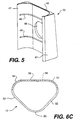
- Figure 5 shows a wedge member 20 designed to clip onto an interior face of the support post 12.
- the wedge member includes a front portion 45 flanked by two contoured lips 47 for clipping, or snap-fitting, the wedge member onto the support post.
- detent means such as internal beads, or ribs, 46 are provided on the internal surface of the wedge member and are spaced at intervals corresponding to the spacing of grooves on the support post.
- the configuration of the internal beads is designed to mate with the configuration of the grooves in the support post.
- the wedge member may comprise one or more internal beads.
- the number, size and shape of the internal beads may be varied for a number of reasons including, for example, the size of the wedge member 20, the size of the spacing of the grooves in the support posts, and the shelving application.
- the internal beads provide vertical support when they are seated in the grooves of a support post. To further secure the wedge member on the support posts, additional vertical support is provided by a wedge action as discussed below. It will therefore be appreciated that the wedge member 20 may be clipped on to the support posts at any incremented height, and further may be translated up and down to any other incremented height.
- a cut-out 48 can be provided in the front portion 45 to view optional numbers on the support post for vertically aligning the wedge member with wedge members on other support posts.
- the outer surface of the front portion is substantially flat in this embodiment to correspond to the substantially flat rear face 44 of the flipper.
- the front portion is also slightly tapered from its upper end to its lower end, such that the lower end is wider and extends toward an interior of the shelving system.
- the taper is shallow to maximize rigidity and minimize the thickness of the wedge member.
- the taper is of the order of 4°.
- the preferred material for the wedge member is a molded plastic, such as reinforced nylon. Such a molded plastic wedge member can be easily clipped on to and off of the support post. However, other materials which provide the desired characteristics may be used.
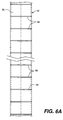
- a vertical support post 12 in accordance with this embodiment of the invention is shown in Figures 6A, 6B and 6C.
- the support post 12 has a generally right equilateral triangular cross-section, which can also be described as a trilobal cross-section.
- a right-angled apex 50 and two flat exterior sides 52 face the exterior of the shelving system, and interior angled apexes 54 and an interior side 56 of the support post face the interior of the shelving assembly.
- the triangular geometry of the support post provides multi-directional stability, particularly in the directions of critical stress forces, i.e., in a direction parallel to the edges of the shelf.
- the support post includes a plurality of horizontal grooves 58 that are preferably, but not necessarily, evenly spaced in the longitudinal direction of the post.
- the grooves are shown to extend entirely across the interior side 56 of the post and partially across the apexes 54 of the post.
- grooves of different lengths could be provided on the support post.
- the grooves receive the internal beads 46 of the sleeve.
- detent tabs and detent steps as disclosed in U.S. Patent No. 4,811,670, could be used without departing from the scope of the present invention as set out in the claims.
- each support post 12 can be fitted with an end cap and the bottom end with a caster, a vertically-adjustable foot, an end cap, etc.
- the bottom end of the support post can be fitted with a stem receptacle for threadably receiving a leveling leg.
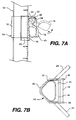
- FIGs 7A and 7B illustrate how the collar support assembly 14 is secured to the support post 12.
- the outer rails 24 and 24' have been deleted in Figure 7A but are shown to be secured to the lateral sides 36 of the collar 16 in Figure 7B.
- the corner support assembly 14 is positioned over the wedge member and the support post.
- the collar 16 and flipper 18 together form a sleeve that fits over the wedge member and the support post.
- the flipper 18 is in the closed, or locked, position as shown in solid lines in Figure 7A
- the rear face 44 of the flipper directs an inward radial compression force against the wedge member 20, in which the front portion 45 is crosshatched for clarity.
- the tapered shape of the wedge creates a wedge action between the wedge member and the flipper for supporting the shelf assembly. It will be appreciated that the greater the weight on the shelf, the greater the downward force and thus the greater the wedging force.
- FIG. 7A will also be referred to in discussing two salient features of the present invention.
- the first feature relates to the ability of the flipper to easily and quickly release the wedging action between the corner support assembly and the wedge member. This frees the shelf to slide up or down the support posts.
- the closed flipper 18 is rotated in the counter-clockwise direction of arrow a to its unlocked position as represented by the dashed lines. By pivoting the flipper about the shaft 38 in this manner, the compression force between the flipper 18 and the wedge member is released. Actuation of the flipper by the user thus allows for quick and reliable releasing of the wedging action.
- Another salient feature of the invention is directed to the ability of the flipper to allow the corner support assembly to slide over the support post and mounted wedge member (or members).
- the flipper 18 normally hangs, by gravity, in substantially the same position shown in solid lines in Figure 7A, i.e., with the lower end 43 directed downwardly.
- the lower (and wider) end of the wedge member will initially contact the flat portion 47 of the upper end of the flipper, causing it to rotate counter-clockwise about the shaft 34 in the direction of arrow a.
- This action raises the flipper toward its unlocked position, whereby the rounded portion 49 of the upper end is substantially opposite the wedge member.
- the contour of the upper end allows the flipper to pass completely over the wedge member.
- the ability of the flipper to be rotated automatically by the wedge member allows the support assembly to be easily raised up the support post.
- the flipper will rotate automatically as described above as it passes over each wedge member and, as it clears the wedge member, rotate in the opposite direction back to its at-rest position.
- this action of the flipper takes place in only one direction, i.e., raising of the support assembly 14 relative to the support post, and in that sense can be described as a ratchet-like movement.
- the rear face 44 of the flipper mates with the front portion 45 of the wedge member and creates a wedging action.
- the flipper will clear the wedge member and the support assembly can slide downward over the support post and mounted wedge member(s).
- the ability of the corner support assembly to translate relative to wedge member mounted on the support post and slide completely thereover enables both the assembly of a shelving system and an adjustment of the height of the shelves to be accomplished with ease.
- a second set of wedge members can be clipped on to the support posts at the desired new height.
- the flippers at the corner support assemblies are then rotated to the unlocked position, releasing the compression force applied to the wedge members by the flippers and allowing the shelf to be raised or lowered.
- the shelf is raised along the support posts to allow the flippers to pass over the second set of wedge members in the manner described above.
- the shelf can be lowered, whereby the flippers will seat on their respective wedge members to create the desired wedging force.
- the first set of wedge members can then be removed from the support posts if desired.
- the shelves can be stacked on the floor one atop the other.
- One set of wedge members for each shelf is positioned on the support posts at the desired shelf heights, and then the support posts are inserted in the aligned corner support assemblies of the shelves.
- Each shelf can then be raised, one-by-one, over the sets of wedge members provided for lower shelves and then over its designated set of wedge members positioned at the desired height. As the shelf passes over the designated wedge members, it is lowered back thereon to allow the flippers, which fall back to the at-rest position once the wedge members are cleared, to engage and seat against the wedge members to create a wedging force for supporting the shelf.
- This static system of supporting the shelves i.e., securing the shelves directly to the support posts, allows for significant load-bearing capacity while providing an easy to assemble and easy to adjust support system.
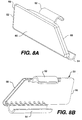
- FIGs 8A and 8B isolated front and rear views of a left-side shield 22 are provided in Figures 8A and 8B, respectively.
- the shield is preferably formed of a molded plastic having the resiliency necessary to be snap-fit over the outer rails.
- the shield 22 is shown to have a substantially flat front face 60 and upper and lower rounded forms, 62 and 64, for snap-fitting onto the outer rails 24'.
- the front face is also defined by one vertical edge 66 and one angled edge 68.
- the upper and lower forms have a substantially semi-circular cross-section and sufficient length to define an extended cylindrical cavity.
- a right-hand shield is shaped in substantially the same way as the left-hand shield, except that the vertical edge and the angled edge are reversed.
- support system of the present invention has been described above in use with substantially triangular-shaped support posts, support posts of other shapes can be used without departing from the scope of the invention. It will be appreciated that the underlying principals of the invention can be used to provide a collar that is contoured to fit around a support post of many shapes and fitted with a rotatable flipper also contoured to complement the outer surface of a wedge member secured to the support post.
- the wedge member as well, can be readily adapted to fit support posts of various shapes.
- the second, third and fourth embodiments described below will better illustrate the ability of the support system of the present invention to be used with different types of support posts.
- the second embodiment illustrated in Figures 9 through 11 shows a support system of the present invention in use with a cylindrical support post.
- the cylindrical post 110 includes annular grooves 112 for receiving and positioning a wedge member 114 in substantially the same manner described above in the first embodiment, i.e., by using detent means comprised of the annular grooves 112 and complementary beads on the interior surface of the wedge member 114.
- detent means comprised of the annular grooves 112 and complementary beads on the interior surface of the wedge member 114.
- the interior surface of the wedge member will be arcuate in shape to complement the surface of the cylindrical support post.
- the outer surface 116 of the wedge member is substantially flat in Figure 9.
- the wedge member is tapered to provide a slightly thicker, lower portion extending toward the interior of the shelving system.
- a collar 118 shown in Figure 10 has a different contour than the collar disclosed in the first embodiment in order to accommodate the shape of the support post.
- an apex 122 of the collar is more rounded to fit the cylindrical support post.
- Rear sides 124 join the lateral sides 126 of the collar to the apex.
- outer rails 128 of the wire shelf frame are preferably, but not necessarily, secured to the rear sides 124 of the collar.
- a flipper 130 of substantially the same shape and characteristics as in the first embodiment is rotatably secured on a shaft 34 extending between the lateral sides 126 of the collar.
- the rear face of the flipper is substantially flat to complement to outer surface 116 of the wedge member.
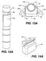
- the outer surface of the wedge member is altered.
- a wedge member 132 having an arcuate outer surface 134 instead of a flat surface is employed.
- This modified wedge member fits the support post like a sleeve.
- detent means as discussed above can be used to secure the wedge member to the support post 110.
- An optional tab could extend from one or both lateral edges of the wedge member for additional support.
- rear sides 124' of the collar 116 are modified as shown in Figure 13A to fit the contour of the wedge member 132.
- the outer rails 128 are secured to the lateral sides of the collar 126.
- the rear face of the flipper 130 is cut out to form a semi-circular cavity 138 for engaging the wedge member.
- the modified complementary shapes of the wedge member and the flipper create a wedging action sufficient to support a shelf when the flipper closes to compress the wedge member, which is still tapered in the manner described above.
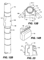
- FIG. 12B, 13B, 14B and 23 Another modification of the second embodiment is shown in Figures 12B, 13B, 14B and 23.
- This modification features a two-piece interlocking sleeve 135 of type used in the SUPER ERECTA SHELF shelving system described above.
- the sleeve 135 is comprised of first and second halves, 137 and 139, respectively, that are snap-fit around the support post and secured to each other by, for example, a tongue and groove arrangement.
- the sleeve includes one or more ribs (unshown) on its interior surface for engaging an equal number of grooves on the support post.
- the sleeve also has a frusto-conically-shaped outer surface, which is widest at the bottom.
- a collar 123 will be provided with a rear section 125 that slopes outwardly from top to bottom to complement the slope of the sleeve.
- the slight slope of the collar 123 is best seen in Figure 23.
- the top view of the support assembly in Figure 13B also illustrates this aspect of the invention.
- the flipper 130 is substantially identical to the flipper illustrated in Figure 14A and discussed above, and likewise creates a wedging force when closed to compress the sleeve.
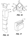
- FIG. 15 through 17 A third embodiment of the present invention is shown in Figures 15 through 17.
- This embodiment features use of a square support post 140 with circumferential grooves 142 equally-spaced in the longitudinal direction.
- an inner surface of wedge member 144 has a right-angled V-shaped cut-out for receiving a corner of the support post.
- Other aspects of the wedge member are the same as in embodiments 1 and 2 described above, i.e., the wedge member includes detent means for mating with the support post and has a tapered outer surface 145.
- Figure 16 shows a collar 146 with a right-angled rear side 148 to complement the outer corner of the support post.
- Outer rails 150 of the shelf frame are preferably secured to lateral sides 152 of the collar in this embodiment.
- Substantially the same flipper 154 as disclosed in the first and second embodiments is rotatably mounted on a shaft between the lateral sides 152 of the collar in the same manner described above.
- the outer surface of the wedge member and the rear face of the flipper are complementary-shaped to mate with each other, and in the illustrated example are both substantially flat.
- tapered wedge member 144' can be formed with a right-angled outer surface as shown in Figure 18.
- flipper member 154' has a right-angled cut-out 156 in its rear face as shown in Figure 19 to complement the shape of the wedge member, which is tapered as described above. The modified flipper is thus able to compress the wedge member in the same manner described above to create a wedging force for supporting a shelf.
- each flange includes a first portion 166 extending radially from the interior post and a second portion 168 transverse to the first portion and having an arcuate outer periphery.
- Longitudinal slots 170 are formed between each adjacent pair of flanges 164.
- Lateral circumferential grooves 172 can also be formed on each flange and evenly spaced in the longitudinal direction.
- a tapered wedge member 174 can be secured to the support post by the same or comparable detent means used to secure the wedge members in the above-described embodiments.
- the wedge member could be secured to the flanged support post by interacting with the longitudinal slots 170.
- the collar 176 shown in Figure 21 has a rounded back section 178 contoured to fit around the circumference of the flanged support post.
- a flipper 180 is rotatably secured between lateral sides 182 of the collar for compressing the wedge member.
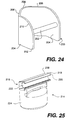
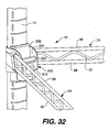
- a fifth embodiment of present invention is shown in various isolated views in Figures 24 through 31 and in an assembled state in Figures 32 and 33.
- This embodiment generally features modified versions of several elements disclosed initially in connection with the first embodiment of the invention. More particularly, modifications of a collar and a flipper (collectively a corner support assembly) and of a tapered wedge member are disclosed below.
- modified elements are designed for use with a triangular support post 12 as shown in Figures 6A through 6C, as in the first disclosed embodiment.
- corner support assemblies and wedges designed for use with support posts of other shapes, including but not limited to the shapes disclosed in the second, third and fourth embodiments.
- a collar 200 of the fifth embodiment is illustrated in Figures 24 and 25.
- the collar includes a cylindrical shaft 202, preferably non-rotatable, secured between two lateral sides 204 for rotatably supporting a flipper.
- a rear section of the collar connecting the two lateral sides is contoured to fit the outward facing shape of the support post.
- the post having a generally triangular cross-section in this embodiment as discussed above, the rear section is thus shaped to have straight portions 206 angled from each lateral side and joined by a rounded apex 208.
- the shaft 202 is secured at substantially the vertical center, or a middle portion, of the collar as shown in Figure 24.
- a top portion 210 of the collar has a larger radius than the collar shown in Figure 3.
- the radius of the top portion 210 in Figure 24 is .875" and the radius of a lower portion 212 of the collar is .250".
- a flipper 214 in accordance with this embodiment is shown in Figures 25 through 29.
- the perspective view of Figure 25 shows the flipper 214 to include, at its top end 216, a flat portion 218 and a rounded portion 220.
- a preferably flat transition portion 219 exists between the flat and rounded portions.
- An open cylindrical cavity 222 receives and contains the shaft 202 of the collar.
- the top end 216 of the flipper is substantially the same as the top end of the flipper disclosed in the first embodiment
- the rounded bottom end 224 is rounded instead of flat like the flipper shown in Figure 4.
- the rounded bottom end 224 also includes a rounded bottom edge 226.
- the bottom edge is preferably chamfered. The rounding of this portion of the flipper provides a semi-circular cavity 228 in which the fingers of the user can comfortably rest when opening the flipper. Rounding the bottom end 224 also makes the flipper less susceptible to being accidentally opened by movement of articles on the shelf below.
- a rear face 229 of the flipper is substantially flat to complement the shape of the wedge member. As shown in Figures 27 and 29, however, the rear face 228 can include pockets 230 to aid in molding.
- a wedge member 232 in this embodiment is substantially the same wedge member shown in Figure 5, but with a greater body length.
- the wedge member 232 in Figure 30 includes a front portion 234 flanked by two contoured lips 236 for clipping, or snap-fitting, the wedge member onto the support post.
- Internal beads, or ribs, 238 are provided on the internal surface of the wedge member and are spaced at intervals corresponding to the spacing of grooves on the support post, as in the first embodiment.
- the cross-sectional view of Figure 31 illustrates the extra body length of the wedge member in this embodiment.
- the extra body length a in this example .625", is added to the top portion of the wedge member 232, making its total length 2.625".
- the extra body length a is not tapered as is the remaining length b of the wedge member.
- the lower end is wider than the upper end so as to extend toward an interior end of the shelving system.
- the taper is of the order of 4°.
- the collar, the flipper and the wedge member of this embodiment work together in the same manner disclosed in the first embodiment to securely support a shelf wire frame 10 on the support posts.
- moving the shaft 202 to the center, or middle portion, of the collar serves to more evenly distribute the stress on the top and bottom rails, 26 and 28, of the wire shelf frame 10 where they are secured (such as by welding) to the collar 200.
- the shelf sits a little higher up on the support assembly than in the first embodiment, and the longer wedge makes it easier to reduce or even eliminate the space between a corner of a shelf mat and the support post, which can trap dirt, food particles or other undesirable items.
- an advantage of the present invention is that it allows a user to quickly and easily change the height of the supported item, e.g., a shelf, to accommodate a variety of shelving applications. Moreover, since the support system allows the shelf frame to slide over the wedge member mounted on the support posts, height adjustment is easy and can be done without tools or without having to remove adjacent shelves.
Landscapes
- Assembled Shelves (AREA)
- Warehouses Or Storage Devices (AREA)
- Furniture Connections (AREA)
- Paper (AREA)
- Vehicle Body Suspensions (AREA)
- Surgical Instruments (AREA)
Claims (23)
- Trägersystem, mitdadurch gekennzeichnet,einem Trägerpfosten (12, 110, 140, 160);einem Keilelement (20, 114, 132, 135, 144, 174, 232), das einen konischen Abschnitt aufweist und an dem Trägerpfosten angeordnet ist; undeiner Trägervorrichtung mit einer Manschette (16, 118, 123, 138, 146, 176, 200), die an einem zu tragenden Element befestigt ist und eine den Trägerpfosten und das Keilelement umgebende Hülse bildet,daß die Trägervorrichtung einen Verriegelungsmechanismus (18, 130, 154, 180, 124) aufweist, der an der Manschette (16, 118, 123, 138, 146, 176, 200) angebracht ist und zusammen mit der Manschette die Hülse bildet; unddaß der Verriegelungsmechanismus durch die Manschette zwischen einer ersten Stellung und einer zweiten Stellung drehbar gehalten ist, wobei der Verriegelungsmechanismus derart angeordnet ist, daß in der ersten Stellung die Hülse den Trägerpfosten (12, 110, 140, 160) und das Keilelement (20, 114, 132, 135, 144, 174, 232) durch Druckkraft des Verriegelungsmechanismus zum Tragen des Elements verklemmt, und in der zweiten Stellung die Druckkraft gelöst ist und die Hülse den Trägerpfosten und das Keilelement nicht verklemmt.
- Trägersystem nach Anspruch 1,
dadurch gekennzeichnet,
daß die Manschette (16, 118, 123, 138, 146, 176, 200) eine Kontur aufweist, um der Querschnittsform des Trägerpfostens (12, 110, 140, 160) zu entsprechen. - Trägersystem nach Anspruch 1 oder 2,
dadurch gekennzeichnet,
daß der Trägerpfosten (12) im wesentlichen die Querschnittsform eines rechtwinkligen, gleichseitigen Dreiecks mit einem abgerundeten rechtwinkligen Scheitel (50) hat. - Trägersystem nach Anspruch 3,
dadurch gekennzeichnet,
daß die Manschette (16) einen ersten und einen zweiten Schenkel (36) und einen hinteren Abschnitt (35) aufweist, welcher den ersten und den zweiten Schenkel verbindet und einen abgerundeten Scheitel (37) besitzt, der dem abgerundeten rechtwinkligen Scheitel (50) des Trägerpfostens (12) entspricht. - Trägersystem nach Anspruch 4,
dadurch gekennzeichnet,
daß die Manschette (16, 118, 123, 138, 146, 176, 200) weiter eine Vorrichtung zur Befestigung des Verriegelungsmechanismus (18, 130, 154, 180, 214) aufweist. - Trägersystem nach Anspruch 5,
dadurch gekennzeichnet,
daß die Befestigungsvorrichtung eine zylindrische Welle (34, 202) aufweist, welche zwischen dem ersten und dem zweiten Schenkel (36, 204) der Manschette (16, 200) befestigt ist. - Trägersystem nach Anspruch 6,
dadurch gekennzeichnet,
daß die zylindrische Welle (34) zwischen oberen Abschnitten des ersten und des zweiten Schenkels (36) der Manschette (16) befestigt ist. - Trägersystem nach Anspruch 6,
dadurch gekennzeichnet,
daß die zylindrische Welle (202) zwischen mittleren Abschnitten des ersten und des zweiten Schenkels (204) der Manschette (200) befestigt ist. - Trägersystem nach einem der Ansprüche 1 bis 8,
dadurch gekennzeichnet,
daß der konische Abschnitt des Keilelements (20, 114, 132, 135, 144, 174, 232) entlang der gesamten Länge des Keilelements verläuft. - Trägersystem nach einem der Ansprüche 1 bis 8,
dadurch gekennzeichnet,
daß sich der konische Abschnitt des Keilelements (20, 114, 132, 135, 144, 174, 232) über einen Teil der Länge des Keilelements erstreckt. - Trägersystem nach einem der Ansprüche 1 bis 8,
dadurch gekennzeichnet,
daß sich der konische Abschnitt des Keilelements (20, 114, 132, 135, 144, 174, 232) über einen unteren Teil der Länge des Keilelements erstreckt. - Trägersystem nach einem der Ansprüche 1 bis 11,
dadurch gekennzeichnet,
daß das Keilelement (20, 114, 132, 135, 144, 174, 232) an den Trägerpfosten (12, 110, 140, 160) aufgesteckt ist, wobei der Verriegelungsmechanismus (18, 130, 154, 180, 214) eine Rückseite aufweist, die mit einer Außenfläche des Keilelements zusammenpaßt. - Trägersystem nach Anspruch 12,
dadurch gekennzeichnet,
daß die Außenfläche (45, 234) und die Rückseite (44, 229) im wesentlichen glatt sind, um einander zu entsprechen. - Trägersystem nach Anspruch 12,
dadurch gekennzeichnet,
daß die Außenfläche (134) konvex und die Rückseite (138) konkav ist, um einander zu entsprechen. - Trägersystem nach Anspruch 12,
dadurch gekennzeichnet,
daß die Außenfläche (145) gewinkelt ist und die Rückseite eine gewinkelte Vertiefung (156) aufweist, um einander zu entsprechen. - Trägersystem nach Anspruch 1,
dadurch gekennzeichnet,
daß das getragene Element, wenn der Verriegelungsmechanismus in der zweiten Position ist, über den Trägerpfosten und das Keilelement laufen kann. - Trägersystem nach einem der Ansprüche 1 bis 16,
dadurch gekennzeichnet,
daß die Trägervorrichtung die Hülse zur Aufnahme des Trägerpfostens (12, 110, 140, 160) und des Keilelements (20, 114, 132, 135, 144, 174, 232) bildet und relativ zu diesen verschiebbar ist, wobei, wenn die Trägervorrichtung in eine erste Richtung verschoben wird, der Verriegelungsmechanismus (18, 130, 154, 180, 214) über das Keilelement läuft und, wenn die Trägervorrichtung in eine zweite Richtung verschoben wird, der Verriegelungsmechanismus auf dem Keilelement aufsitzt und eine Keilkraft erzeugt. - Trägersystem nach Anspruch 17,
gekennzeichnet durch
eine Vorrichtung zur Betätigung des Verriegelungsmechanismus (18, 130, 154, 180, 214) in die zweite Stellung, wenn die Trägervorrichtung in die erste Richtung gleitet, um es dem Verriegelungsmechanismus zu ermöglichen, über das Keilelement (20, 114, 132, 135, 144, 174, 232) zu laufen. - Trägersystem nach Anspruch 1,
dadurch gekennzeichnet,
daß der Verriegelungsmechanismus (18, 130, 154, 180) eine flache Unterseite (43) aufweist. - Trägersystem nach Anspruch 1,
dadurch gekennzeichnet,
daß der Verriegelungsmechanismus (214) eine abgerundete Unterseite (43) aufweist. - Trägersystem nach einem der Ansprüche 1 bis 20,
dadurch gekennzeichnet,
daß der Verriegelungsmechanismus (18, 130, 154, 180, 214) in der ersten Stellung das Element durch eine Keilwirkung mit dem Keilelement (20, 114, 132, 135, 144, 174, 232) trägt. - Trägersystem nach einem der Ansprüche 1 bis 21,
dadurch gekennzeichnet,
daß der Verriegelungsmechanismus (18, 130, 154, 180, 214) in der zweiten Stellung die auf den Trägerpfosten (12, 110, 140, 160 und das Keilelement (20, 114, 132, 135, 144, 174, 232) ausgeübte Druckkraft löst. - Trägersystem nach einem der Ansprüche 1 bis 22,
dadurch gekennzeichnet,
daß der Verriegelungsmechanismus (18, 130, 154, 180, 214) in der zweiten Stellung über den Trägerpfosten (12, 110, 140, 160 und das Keilelement (20, 114, 132, 135, 144, 174, 232) verschiebbar ist.
Applications Claiming Priority (3)
| Application Number | Priority Date | Filing Date | Title |
|---|---|---|---|
| US227 | 1979-01-02 | ||
| US22795P | 1995-06-15 | 1995-06-15 | |
| PCT/US1996/010356 WO1997000033A1 (en) | 1995-06-15 | 1996-06-14 | Support system with quick-adjust support assembly |
Publications (2)
| Publication Number | Publication Date |
|---|---|
| EP0836400A1 EP0836400A1 (de) | 1998-04-22 |
| EP0836400B1 true EP0836400B1 (de) | 2000-09-06 |
Family
ID=21690505
Family Applications (1)
| Application Number | Title | Priority Date | Filing Date |
|---|---|---|---|
| EP96922472A Expired - Lifetime EP0836400B1 (de) | 1995-06-15 | 1996-06-14 | Systemträger mit einer schnelljustiervorrichtung der trägeranlage |
Country Status (8)
| Country | Link |
|---|---|
| US (1) | US6017009A (de) |
| EP (1) | EP0836400B1 (de) |
| JP (1) | JP4037449B2 (de) |
| AU (1) | AU713464B2 (de) |
| CA (1) | CA2224676C (de) |
| DE (1) | DE69610210T2 (de) |
| ES (1) | ES2150133T3 (de) |
| WO (1) | WO1997000033A1 (de) |
Cited By (1)
| Publication number | Priority date | Publication date | Assignee | Title |
|---|---|---|---|---|
| CN108354390A (zh) * | 2018-01-19 | 2018-08-03 | 郑州升达经贸管理学院 | 一种美术三维展示系统及其使用方法 |
Families Citing this family (57)
| Publication number | Priority date | Publication date | Assignee | Title |
|---|---|---|---|---|
| US6113042A (en) * | 1997-07-16 | 2000-09-05 | Metro Industries, Inc. | Self-adjusting support system |
| US6158600A (en) * | 1998-09-18 | 2000-12-12 | Metro Industries, Inc. | Shelving system having a tiltable shelf with an adjustable side |
| AUPP927799A0 (en) * | 1999-03-18 | 1999-04-15 | Mondo Medical Limited | Support bracket |
| US6357611B1 (en) * | 2000-03-31 | 2002-03-19 | Protend Co., Ltd | Sectional rack |
| US6431090B1 (en) * | 2000-04-28 | 2002-08-13 | L & P Property Management Company | Adjustable shelving with tiltable shelves |
| AU783728B2 (en) * | 2001-09-03 | 2005-12-01 | Mantova Marketing Pty Limited | A shelving system |
| US6776466B2 (en) | 2002-10-24 | 2004-08-17 | Maax-Ksd Corporation | Adjustable cabinet shelf support system with slidability |
| US7086633B2 (en) * | 2002-11-14 | 2006-08-08 | Metro Industries Inc. | Quick adjust support system with trapped or integral wedge |
| DE20302942U1 (de) * | 2003-02-21 | 2003-05-28 | Chambrair Gmbh | Regalsystem |
| WO2005013767A1 (fr) * | 2003-08-11 | 2005-02-17 | Shenzhen Longgang District Longgang Huilongpu Kin Hing Steel Furniture Factory | Structure de plaque porteuse de forme conique semi-cricoide |
| EP1817980A2 (de) | 2003-11-21 | 2007-08-15 | Intermetro Industries Corporation | Schnell einstellbares Stützsystem mit einem integralen oder gefangenen Keil |
| US20080142322A1 (en) * | 2004-06-30 | 2008-06-19 | Deborah Barker | Expandable container |
| US7325697B2 (en) * | 2005-02-02 | 2008-02-05 | Seville Classics, Inc. | Storage bin for use with shelving system |
| US8640893B2 (en) * | 2005-07-01 | 2014-02-04 | Spg International Llc | Adjustable shelving system |
| DE102005031947A1 (de) * | 2005-07-08 | 2007-01-11 | Rheinmetall Waffe Munition Gmbh | Vorrichtung zur Befestigung eines auf bzw. an einem Körper zu befestigenden Teils |
| US7401754B2 (en) * | 2005-09-12 | 2008-07-22 | Metro Industries, Inc. | Shelf support system having a cylindrical support post and providing improved stability and rigidity |
| US20070181760A1 (en) * | 2005-12-21 | 2007-08-09 | Segall Paul M | Apparatus for a Shelf Support System Attached Together by a Wedge |
| US20070256613A1 (en) * | 2006-05-05 | 2007-11-08 | Lim Gary M | Connector for shelving |
| US8225946B2 (en) | 2006-06-29 | 2012-07-24 | Simplehuman, Llc | Shelving system |
| KR100854827B1 (ko) * | 2006-11-20 | 2008-08-27 | 엘지전자 주식회사 | 냉장고 선반의 높이조절 구조 |
| KR100833370B1 (ko) * | 2006-11-20 | 2008-05-28 | 엘지전자 주식회사 | 냉장고 선반의 높이조절 구조 |
| US8226184B2 (en) * | 2006-11-20 | 2012-07-24 | Lg Electronics Inc. | Height adjusting apparatus of shelf for refrigerator |
| US7896300B2 (en) * | 2007-08-06 | 2011-03-01 | Larossa Donato | Supporting mount removably fixable to a generally vertical columnar structure |
| US7819369B2 (en) * | 2007-08-06 | 2010-10-26 | Larossa Donato | Supporting mount removably fixable to a generally vertical columnar structure |
| CA2645529C (en) * | 2007-11-29 | 2013-07-02 | Wenger Corporation | Portable staging and leg bracket therefor |
| US20090188880A1 (en) * | 2008-01-28 | 2009-07-30 | Simplehuman, Llc | Shelving system |
| US20090266952A1 (en) * | 2008-04-24 | 2009-10-29 | Penn United Technologies, Inc. | Magnetic Organizer |
| EP2191757A2 (de) | 2008-12-01 | 2010-06-02 | Simplehuman LLC | Regalsystem |
| USD622990S1 (en) | 2009-03-20 | 2010-09-07 | Simplehuman, Llc | Shelving system |
| USD628841S1 (en) | 2009-12-01 | 2010-12-14 | Simplehuman, Llc | Shelving system |
| USD651838S1 (en) | 2010-03-12 | 2012-01-10 | Simplehuman, Llc | Shelving system |
| USD651837S1 (en) | 2010-03-12 | 2012-01-10 | Simplehuman, Llc | Shelving system |
| US9119471B2 (en) | 2013-03-14 | 2015-09-01 | Spg International Llc | Support bracket |
| US9249818B2 (en) * | 2013-08-30 | 2016-02-02 | Pro-Mart Industries, Inc. | Shelving connector and method of manufacture |
| US9770122B2 (en) | 2013-10-01 | 2017-09-26 | Spg International Llc | Shelving system |
| USD727060S1 (en) | 2014-03-12 | 2015-04-21 | Simplehuman, Llc | Shelving system |
| USD726441S1 (en) | 2014-03-12 | 2015-04-14 | Simplehuman, Llc | Shelving system |
| US9339151B2 (en) | 2014-03-13 | 2016-05-17 | Simplehuman, Llc | Shelving system with obscurable shelving |
| USD734956S1 (en) | 2014-03-13 | 2015-07-28 | Simplehuman, Llc | Shelving system |
| US9943192B2 (en) | 2014-03-13 | 2018-04-17 | Simplehuman, Llc | Shelving system with obscurable shelving |
| US9883742B2 (en) | 2014-03-14 | 2018-02-06 | Simplehuman, Llc | Shower caddy with shelf adjustably maounted along an elongate support member |
| DK3006303T3 (da) * | 2014-10-06 | 2022-11-14 | Landgard Service Gmbh | Mobilt varetransport- og præsentationsstativ |
| USD769641S1 (en) | 2015-02-23 | 2016-10-25 | Simplehuman, Llc | Shower caddy |
| USD770197S1 (en) | 2015-02-23 | 2016-11-01 | Simplehuman, Llc | Shower caddy |
| USD770198S1 (en) | 2015-02-25 | 2016-11-01 | Simplehuman, Llc | Shelving system |
| KR20180115287A (ko) * | 2016-02-17 | 2018-10-22 | 시코 인코퍼레이티드 | 휴대용 스테이지 시스템 |
| CA2973716A1 (en) * | 2016-07-20 | 2018-01-20 | As Ip Holdco, Llc | Accessory rail system for bath or shower walls |
| USD824189S1 (en) | 2017-02-23 | 2018-07-31 | Simplehuman, Llc | Shower caddy |
| JP7115952B2 (ja) * | 2018-10-03 | 2022-08-09 | 株式会社ホシプラ | 無段階調整ブッシュ |
| US10925394B2 (en) * | 2019-01-31 | 2021-02-23 | Intermetro Industries Corporation | Height adjustment apparatus for workstations, work tables, shelf systems and rack systems |
| US11388997B1 (en) * | 2019-08-09 | 2022-07-19 | Interdesign, Inc. | Accessory flip lock for vertical pole |
| CH717061A1 (de) | 2020-01-23 | 2021-07-30 | Visplay Int Ag | Struktursystem zum modularen Aufbau von Regalen und Regal. |
| US11066022B1 (en) * | 2020-04-06 | 2021-07-20 | King Roof Industrial Co., Ltd. | Positioning clamp and carrier using the same |
| US11555574B2 (en) * | 2020-05-20 | 2023-01-17 | OmniMax USA, LLC | Height adjustable monitor arm mounting assembly |
| TWI734609B (zh) * | 2020-09-10 | 2021-07-21 | 柯佳男 | 置物架鍛造沖壓結構 |
| US20220160123A1 (en) * | 2020-11-25 | 2022-05-26 | Decolin Inc. | Pole caddies with adjustable basket brackets |
| US11686425B2 (en) * | 2021-05-07 | 2023-06-27 | Fresenius Medical Care Holdings, Inc. | Mechanical lifts and related methods of lifting medical fluid containers |
Family Cites Families (21)
| Publication number | Priority date | Publication date | Assignee | Title |
|---|---|---|---|---|
| US446472A (en) * | 1891-02-17 | Benjamin f | ||
| US138385A (en) * | 1873-04-29 | Improvement in stove-pipe shelves | ||
| US2849249A (en) * | 1955-10-20 | 1958-08-26 | Annette E Fridolph | Clamping device |
| US3424111A (en) * | 1967-03-30 | 1969-01-28 | Louis Maslow | Readily assemblable and adjustable shelving |
| US3472476A (en) * | 1967-07-31 | 1969-10-14 | Harold R Johnson | Slide lock |
| US3604369A (en) * | 1969-02-10 | 1971-09-14 | Louis Maslow | Shelving |
| US3675598A (en) * | 1970-11-04 | 1972-07-11 | William Hodges & Co Inc | Adjustable shelving |
| US3964404A (en) * | 1975-05-09 | 1976-06-22 | American Hospital Supply Corporation | Shelf and corner post assembly |
| US4430017A (en) * | 1982-04-29 | 1984-02-07 | Mardan Corp. | Musical instrument support |
| US4754712A (en) * | 1984-05-17 | 1988-07-05 | Amco Corporation | Adjustable rack of shelves |
| US4637323A (en) * | 1984-06-29 | 1987-01-20 | United Steel & Wire Company | Corner structure for adjustable shelving (with opposed clamping members) |
| US4596484A (en) * | 1984-10-05 | 1986-06-24 | Velbon International Corporation | Lock for telescoping tubular support |
| AU5180786A (en) * | 1985-01-03 | 1986-07-10 | U-Rect-It Pty. Ltd. | Clamping device |
| GB8504735D0 (en) * | 1985-02-23 | 1985-03-27 | Greening N Ltd | Adjustable shelving |
| US4629077A (en) * | 1985-04-19 | 1986-12-16 | Niblock George W | Shelf support system |
| US5279231A (en) * | 1987-07-24 | 1994-01-18 | Metro Industries Inc. | Plastic frame system having a triangular support post |
| US5271337A (en) * | 1987-07-24 | 1993-12-21 | Metro Industries Inc. | Plastic frame system having a triangular support post |
| US4811670A (en) * | 1987-07-24 | 1989-03-14 | Intermetro Industries Corporation | Shelf support system having a triangular support post |
| US5039043A (en) * | 1990-04-05 | 1991-08-13 | Hodge Robert B | Post holder |
| CA2080714C (en) * | 1991-10-28 | 2001-07-03 | Bradley Jon Carlson | Modular shelving system with a quick-change shelf feature |
| US5772162A (en) * | 1996-10-16 | 1998-06-30 | Lin; Chin-Liang | Drop-bottle stand |
-
1996
- 1996-06-14 WO PCT/US1996/010356 patent/WO1997000033A1/en active IP Right Grant
- 1996-06-14 ES ES96922472T patent/ES2150133T3/es not_active Expired - Lifetime
- 1996-06-14 DE DE69610210T patent/DE69610210T2/de not_active Expired - Lifetime
- 1996-06-14 EP EP96922472A patent/EP0836400B1/de not_active Expired - Lifetime
- 1996-06-14 CA CA002224676A patent/CA2224676C/en not_active Expired - Lifetime
- 1996-06-14 AU AU63334/96A patent/AU713464B2/en not_active Expired
- 1996-06-14 JP JP50335997A patent/JP4037449B2/ja not_active Expired - Lifetime
- 1996-06-14 US US08/973,401 patent/US6017009A/en not_active Expired - Lifetime
Cited By (2)
| Publication number | Priority date | Publication date | Assignee | Title |
|---|---|---|---|---|
| CN108354390A (zh) * | 2018-01-19 | 2018-08-03 | 郑州升达经贸管理学院 | 一种美术三维展示系统及其使用方法 |
| CN108354390B (zh) * | 2018-01-19 | 2020-11-10 | 郑州升达经贸管理学院 | 一种美术三维展示系统及其使用方法 |
Also Published As
| Publication number | Publication date |
|---|---|
| DE69610210T2 (de) | 2001-04-26 |
| AU6333496A (en) | 1997-01-15 |
| CA2224676A1 (en) | 1997-01-03 |
| JP4037449B2 (ja) | 2008-01-23 |
| ES2150133T3 (es) | 2000-11-16 |
| EP0836400A1 (de) | 1998-04-22 |
| DE69610210D1 (de) | 2000-10-12 |
| US6017009A (en) | 2000-01-25 |
| CA2224676C (en) | 2007-09-25 |
| JPH11507582A (ja) | 1999-07-06 |
| AU713464B2 (en) | 1999-12-02 |
| WO1997000033A1 (en) | 1997-01-03 |
Similar Documents
| Publication | Publication Date | Title |
|---|---|---|
| EP0836400B1 (de) | Systemträger mit einer schnelljustiervorrichtung der trägeranlage | |
| US6113042A (en) | Self-adjusting support system | |
| EP2464257B1 (de) | Regalhaltesystem mit zylinderförmiger stütze und bereitstellung von erhöhter stabilität und starrheit | |
| US7267310B2 (en) | Quick adjust support system with trapped or integral wedge | |
| CA1327183C (en) | Shelf support system having a triangular support post | |
| US5303645A (en) | Adjustable shelving system having friction increasing mating surfaces | |
| US4750626A (en) | Removable conical corner structure for shelving | |
| CA1308760C (en) | Modular utility cart including improved structures for securing intermediate and top shelves to corner posts | |
| EP0687430B1 (de) | Ein Kunststoffrahmensystem mit einer dreieckigen Säule | |
| US7886674B2 (en) | Interlocking, interchangeable support base system | |
| US5531167A (en) | Locking hanger bracket for use in a quick-change modular shelving system and shelving system employing such hanger bracket | |
| JPH11155655A (ja) | モジュール式棚システム | |
| US3480155A (en) | Steel shelving | |
| CA1283686C (en) | Table leg assembly and method of assembling same | |
| EP1817980A2 (de) | Schnell einstellbares Stützsystem mit einem integralen oder gefangenen Keil | |
| CA2557313A1 (en) | Quick adjust support system with trapped or integral wedge | |
| GB2284986A (en) | Leg for a table | |
| CA2209717A1 (en) | Corner assembly for use with a flanged support post |
Legal Events
| Date | Code | Title | Description |
|---|---|---|---|
| PUAI | Public reference made under article 153(3) epc to a published international application that has entered the european phase |
Free format text: ORIGINAL CODE: 0009012 |
|
| AK | Designated contracting states |
Kind code of ref document: A1 Designated state(s): DE ES FR GB IT NL |
|
| 17P | Request for examination filed |
Effective date: 19980113 |
|
| 17Q | First examination report despatched |
Effective date: 19980713 |
|
| GRAG | Despatch of communication of intention to grant |
Free format text: ORIGINAL CODE: EPIDOS AGRA |
|
| GRAG | Despatch of communication of intention to grant |
Free format text: ORIGINAL CODE: EPIDOS AGRA |
|
| GRAH | Despatch of communication of intention to grant a patent |
Free format text: ORIGINAL CODE: EPIDOS IGRA |
|
| GRAH | Despatch of communication of intention to grant a patent |
Free format text: ORIGINAL CODE: EPIDOS IGRA |
|
| GRAA | (expected) grant |
Free format text: ORIGINAL CODE: 0009210 |
|
| AK | Designated contracting states |
Kind code of ref document: B1 Designated state(s): DE ES FR GB IT NL |
|
| PG25 | Lapsed in a contracting state [announced via postgrant information from national office to epo] |
Ref country code: NL Free format text: LAPSE BECAUSE OF FAILURE TO SUBMIT A TRANSLATION OF THE DESCRIPTION OR TO PAY THE FEE WITHIN THE PRESCRIBED TIME-LIMIT Effective date: 20000906 |
|
| ET | Fr: translation filed | ||
| REF | Corresponds to: |
Ref document number: 69610210 Country of ref document: DE Date of ref document: 20001012 |
|
| ITF | It: translation for a ep patent filed |
Owner name: BUGNION S.P.A. |
|
| REG | Reference to a national code |
Ref country code: ES Ref legal event code: FG2A Ref document number: 2150133 Country of ref document: ES Kind code of ref document: T3 |
|
| NLV1 | Nl: lapsed or annulled due to failure to fulfill the requirements of art. 29p and 29m of the patents act | ||
| PLBE | No opposition filed within time limit |
Free format text: ORIGINAL CODE: 0009261 |
|
| STAA | Information on the status of an ep patent application or granted ep patent |
Free format text: STATUS: NO OPPOSITION FILED WITHIN TIME LIMIT |
|
| 26N | No opposition filed | ||
| REG | Reference to a national code |
Ref country code: GB Ref legal event code: IF02 |
|
| REG | Reference to a national code |
Ref country code: FR Ref legal event code: PLFP Year of fee payment: 20 |
|
| PGFP | Annual fee paid to national office [announced via postgrant information from national office to epo] |
Ref country code: GB Payment date: 20150629 Year of fee payment: 20 Ref country code: DE Payment date: 20150629 Year of fee payment: 20 Ref country code: ES Payment date: 20150626 Year of fee payment: 20 |
|
| PGFP | Annual fee paid to national office [announced via postgrant information from national office to epo] |
Ref country code: FR Payment date: 20150617 Year of fee payment: 20 |
|
| PGFP | Annual fee paid to national office [announced via postgrant information from national office to epo] |
Ref country code: IT Payment date: 20150625 Year of fee payment: 20 |
|
| REG | Reference to a national code |
Ref country code: DE Ref legal event code: R071 Ref document number: 69610210 Country of ref document: DE |
|
| REG | Reference to a national code |
Ref country code: GB Ref legal event code: PE20 Expiry date: 20160613 |
|
| PG25 | Lapsed in a contracting state [announced via postgrant information from national office to epo] |
Ref country code: GB Free format text: LAPSE BECAUSE OF EXPIRATION OF PROTECTION Effective date: 20160613 |
|
| REG | Reference to a national code |
Ref country code: ES Ref legal event code: FD2A Effective date: 20160926 |
|
| PG25 | Lapsed in a contracting state [announced via postgrant information from national office to epo] |
Ref country code: ES Free format text: LAPSE BECAUSE OF EXPIRATION OF PROTECTION Effective date: 20160615 |