EP0836261A1 - Selbsttragender Endverschluss für Energiekabel - Google Patents
Selbsttragender Endverschluss für Energiekabel Download PDFInfo
- Publication number
- EP0836261A1 EP0836261A1 EP97401808A EP97401808A EP0836261A1 EP 0836261 A1 EP0836261 A1 EP 0836261A1 EP 97401808 A EP97401808 A EP 97401808A EP 97401808 A EP97401808 A EP 97401808A EP 0836261 A1 EP0836261 A1 EP 0836261A1
- Authority
- EP
- European Patent Office
- Prior art keywords
- cable
- insulating
- end according
- chamber
- stripped
- Prior art date
- Legal status (The legal status is an assumption and is not a legal conclusion. Google has not performed a legal analysis and makes no representation as to the accuracy of the status listed.)
- Withdrawn
Links
Images
Classifications
-
- H—ELECTRICITY
- H02—GENERATION; CONVERSION OR DISTRIBUTION OF ELECTRIC POWER
- H02G—INSTALLATION OF ELECTRIC CABLES OR LINES, OR OF COMBINED OPTICAL AND ELECTRIC CABLES OR LINES
- H02G15/00—Cable fittings
- H02G15/02—Cable terminations
- H02G15/06—Cable terminating boxes, frames or other structures
- H02G15/064—Cable terminating boxes, frames or other structures with devices for relieving electrical stress
- H02G15/068—Cable terminating boxes, frames or other structures with devices for relieving electrical stress connected to the cable shield only
-
- H—ELECTRICITY
- H02—GENERATION; CONVERSION OR DISTRIBUTION OF ELECTRIC POWER
- H02G—INSTALLATION OF ELECTRIC CABLES OR LINES, OR OF COMBINED OPTICAL AND ELECTRIC CABLES OR LINES
- H02G15/00—Cable fittings
- H02G15/02—Cable terminations
- H02G15/06—Cable terminating boxes, frames or other structures
-
- H—ELECTRICITY
- H02—GENERATION; CONVERSION OR DISTRIBUTION OF ELECTRIC POWER
- H02G—INSTALLATION OF ELECTRIC CABLES OR LINES, OR OF COMBINED OPTICAL AND ELECTRIC CABLES OR LINES
- H02G15/00—Cable fittings
- H02G15/20—Cable fittings for cables filled with or surrounded by gas or oil
- H02G15/22—Cable terminations
Definitions
- the present invention relates to a self-supporting end electric cable, especially high cable or very high voltage, said cable comprising a core conductive, insulation, semiconductor screen, conductive metal screen and a protective sheath outside.
- Such an end is more especially intended for the connection of an underground line consisting of a power cable to an overhead network or to an appliance.
- Such an end is made self-supporting by its insulating and rigid tubular body. It thus has the advantage avoid the use of posts or other structure support before then necessarily extend over the total length of the cable end when it has an insulating but relatively tubular body flexible. However, it has the disadvantage of not avoiding the risk of explosion and projection of debris, when electrical faults such as abnormal overvoltages or internal electric arcs in the end.
- the object of the present invention is to resolve the problems with self-supporting cable ends energy, so as to avoid the aforementioned risks without however, lead to a more complex realization and / or cumbersome.
- It relates to a self-supporting end of the type cited above, characterized in that it comprises at least one opening in the lower part of said chamber, for bringing the chamber to external ambient pressure and ventilation by air circulation in the room, and a set of second insulating skirts, mounted on the insulation stripped of the cable, between the deflector cone and the end piece connection terminal.
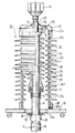
- This single figure represents a self-supporting end of power cable, partially illustrated in section and elevation.
- reference 1 designates a cable of energy from an underground line, or more precisely the terminal portion of this cable that has been cleared from the line underground and is equipped with one end 10, according to the present invention.
- This cable comprises a central conductive core 2, a insulation 3, a semiconductor screen 4, a metal screen 5 and an outer protective sheath 6. The portion end of the cable is successively stripped on one part of its length.
- the end 10 comprises this terminal portion of the cable and equipment mounted on the stripped part of this one.
- These devices include a deflector cone electric field 11 mounted on the stripped semiconductor screen 4 and an adjoining portion of the stripped insulation 3, a set 12 of insulating skirts 13 associated with the deflector cone and mounted on the stripped insulation 3, and a terminal end piece connection conductor 14 mounted on the conductive core naked. They also have a rigid tubular body and insulator 15, which surrounds the deflector cone without contact 11 and the set 12 of insulating skirts 13, a support 16 of fixing the terminal portion of the cable relative to the ground and a cap 17 received on the body opposite the support.
- the set 12 of insulating skirts 13 is preferably consisting of a series of subsets or skirts insulators, which are more easily placed on the cable and are then joined to each other and to the cone deflector for their continuity.
- the tubular body 15, which is not in contact with the assembly 12, can on the other hand be in contact with the deflector cone if this is planned to peripheral dimensions larger than those represented.
- the mounting bracket is a metal bracket horizontal, with a passage for the cable.
- the part end of the cable is fixed by its bare metal screen to support 16.
- This attachment is made, in this example, by a couple of complementary retaining rings 18 and 19, the ring 18 can be welded under the support around the cable passage and ring 19 be retained on the screen metal and be received and maintained by the ring 18.
- a flange 20 internally shouldered is integral and protruding above the support around the passage for the cable. She receives and retains the body 15, for maintaining the body on the support and coaxially around the terminal part of the cable, thus making the end self-supporting.
- a grounding connection system 21 is mounted on the bare metal screen 5, just below the support fixing 16 and retaining rings 18 and 19. This system connection can be insulated or not, so as as known, according to the requirements of the installations.
- the cap 17 is conductive and generally metallic. It has a passage provided in a known manner to allow axial guidance of the cable core on which is mounted the connection end piece 14 and to ensure a seal around the stripped core and the part rear of the connection piece.
- a sleeve seal 22 surrounds the rear part of the end piece connection and get along on the bare soul up to the whole 12 insulating skirts 13. He wears a centering ring 23, which is capable of sliding axially in the passage of the cap, and an outer sealing ring 24, which forms a sealing bellows maintained on the one hand on the periphery of the sleeve 22 and on the other hand on the periphery of the passage of the cap 17.
- the rigid insulating body 15 delimits with the support 16 and the cap 17 an interior chamber 25 around the cone deflector 11 and of the assembly 12 of the insulating skirts 13 in place on the cable.
- the lower end of this chamber can be delimited not by the support 16 but by the deflector cone 11 when the latter is in contact with the insulating body 15.
- This room 25 communicates with the outside by at minus an opening provided in its lower part, such that the opening 26a in the support 16 and / or the opening 26b in the flange 20, and / or the opening 26c in the part lower part of the body 15, and / or the opening 26d also in the body 15 but slightly above the deflector cone, for bringing the chamber to the outside ambient pressure and its ventilation by free air circulation in this one. It also preferably presents to favor this air circulation at least one other opening in its upper part and / or its intermediate part, such as opening 27a in the cap, opening 27b or 27c in the body 15.
- the insulating body 15 advantageously has a tubular set of externally tiered insulating skirts 28 and also preferably another set of skirts insulating layers internally 29, over its entire height, for an elongation resulting from the creepage distances externally as internally, between the cap and the metal support.
- This insulating and rigid body 15 is constituted by example by a tube made of porcelain or composite material mechanically resistant over time to conditions severe surrounding.
- the composite material is in particularly an epoxy resin loaded with glass fibers. he may alternatively be a polyurethane or another material similar.
- the exterior and interior skirts are shaped insulator fins. They can consist of a in one piece or by fin modules. Alternatively the inner skirts 29 are formed by rings, or again by spirals which are brought back and posed with or without discontinuity on the tube.
- the tube is made by presenting its outer skirts while the interior skirts are attached. These are then advantageously made of silicone. Skirts exterior can also be made of silicone and then also be reported on the tube initially smooth on the outside.
- Such a self-supporting end solves the problems posed by the self-supporting ends of the known art. In indeed, it confines in room 25 the dangers potential in the event of a default, without requiring a special rupture zone since this chamber is outdoor ambient pressure with air circulating freely in the bedroom. The ventilation by this air circulation avoids any condensation of humidity in the room.
- the end may include a material solid dielectric filling of the chamber, consisting by an alveolar compound and in particular by elements at least partially filling the room.
- a dielectric material is preferably chosen for have a high thermal conductivity. He is in particular formed by beads or silica powder or alumina. Air circulation in the room promotes heat exchange with the outside.
Landscapes
- Cable Accessories (AREA)
Applications Claiming Priority (4)
| Application Number | Priority Date | Filing Date | Title |
|---|---|---|---|
| FR9609800A FR2752106B1 (fr) | 1996-08-02 | 1996-08-02 | Extremite auto-porteuse de cable d'energie |
| FR9609800 | 1996-08-02 | ||
| FR9615641A FR2752107B1 (fr) | 1996-08-02 | 1996-12-19 | Extremite auto-porteuse de cable d'energie |
| FR9615641 | 1996-12-19 |
Publications (1)
| Publication Number | Publication Date |
|---|---|
| EP0836261A1 true EP0836261A1 (de) | 1998-04-15 |
Family
ID=26232904
Family Applications (1)
| Application Number | Title | Priority Date | Filing Date |
|---|---|---|---|
| EP97401808A Withdrawn EP0836261A1 (de) | 1996-08-02 | 1997-07-28 | Selbsttragender Endverschluss für Energiekabel |
Country Status (2)
| Country | Link |
|---|---|
| EP (1) | EP0836261A1 (de) |
| FR (1) | FR2752107B1 (de) |
Families Citing this family (1)
| Publication number | Priority date | Publication date | Assignee | Title |
|---|---|---|---|---|
| FR2784814B1 (fr) * | 1998-10-19 | 2001-02-16 | Sagem | Tete de cable auto-porteuse |
Citations (7)
| Publication number | Priority date | Publication date | Assignee | Title |
|---|---|---|---|---|
| DE360499C (de) * | 1922-10-03 | Haefely & Cie Ag Emil | Elektrischer Isolator | |
| US2748184A (en) * | 1951-04-04 | 1956-05-29 | G & W Electric Speciality Co | High voltage electric terminator |
| GB908998A (en) * | 1959-04-06 | 1962-10-24 | Emile Haefely & Cie S A | Fluidtight lead-in insulator |
| FR2316709A1 (fr) * | 1975-07-03 | 1977-01-28 | Haefely & Cie Ag Emil | Isolateur a haute tension de traversee, dispose a l'air libre, pour installations electriques isolees a l'hexafluorure de soufre gazeux comprime |
| FR2389206A1 (fr) * | 1977-04-29 | 1978-11-24 | Sprecher & Schuh Ag | Enveloppe isolante en ceramique sous pression de gaz pour appareillage electrique |
| EP0080192A2 (de) * | 1981-11-20 | 1983-06-01 | Mitsubishi Denki Kabushiki Kaisha | Durchführung für gasisolierte elektrische Anlagen |
| FR2590739A1 (fr) * | 1985-11-28 | 1987-05-29 | Kabelmetal Electro Gmbh | Tete de cable, notamment pour cable a haute tension isole par de la matiere synthetique |
-
1996
- 1996-12-19 FR FR9615641A patent/FR2752107B1/fr not_active Expired - Fee Related
-
1997
- 1997-07-28 EP EP97401808A patent/EP0836261A1/de not_active Withdrawn
Patent Citations (7)
| Publication number | Priority date | Publication date | Assignee | Title |
|---|---|---|---|---|
| DE360499C (de) * | 1922-10-03 | Haefely & Cie Ag Emil | Elektrischer Isolator | |
| US2748184A (en) * | 1951-04-04 | 1956-05-29 | G & W Electric Speciality Co | High voltage electric terminator |
| GB908998A (en) * | 1959-04-06 | 1962-10-24 | Emile Haefely & Cie S A | Fluidtight lead-in insulator |
| FR2316709A1 (fr) * | 1975-07-03 | 1977-01-28 | Haefely & Cie Ag Emil | Isolateur a haute tension de traversee, dispose a l'air libre, pour installations electriques isolees a l'hexafluorure de soufre gazeux comprime |
| FR2389206A1 (fr) * | 1977-04-29 | 1978-11-24 | Sprecher & Schuh Ag | Enveloppe isolante en ceramique sous pression de gaz pour appareillage electrique |
| EP0080192A2 (de) * | 1981-11-20 | 1983-06-01 | Mitsubishi Denki Kabushiki Kaisha | Durchführung für gasisolierte elektrische Anlagen |
| FR2590739A1 (fr) * | 1985-11-28 | 1987-05-29 | Kabelmetal Electro Gmbh | Tete de cable, notamment pour cable a haute tension isole par de la matiere synthetique |
Also Published As
| Publication number | Publication date |
|---|---|
| FR2752107B1 (fr) | 1998-09-04 |
| FR2752107A1 (fr) | 1998-02-06 |
Similar Documents
| Publication | Publication Date | Title |
|---|---|---|
| EP0777926B1 (de) | Verbindung von energiekabeln | |
| CA2047346C (fr) | Cable sous-marin de telecommunications a fibres optiques | |
| CA2246651C (fr) | Dispositif de protection etanche pour une jonction de cables haute tension | |
| EP0836261A1 (de) | Selbsttragender Endverschluss für Energiekabel | |
| EP0275772B1 (de) | Gehäuse für elektrische Vorrichtung, insbesondere für Überspannungsableiter, mit einer isolierenden Formumhüllung | |
| JPH023241B2 (de) | ||
| FR2752106A1 (fr) | Extremite auto-porteuse de cable d'energie | |
| CA2069800C (fr) | Dispositif de protection contre les effets d'un claquage pour extremite de cable electrique | |
| KR20190130872A (ko) | 피뢰기 삽입형 종단접속재 | |
| FR2814275A1 (fr) | Disjoncteur a isolation au gaz avec un transformateur de courant electronique integre | |
| EP0552082A1 (de) | Schutz für Mittelspannungskabelendverschluss | |
| EP0833421B1 (de) | Garnitur für Kabelendverschluss und Material für die Bildung der Garnitur | |
| EP0525635A1 (de) | Vakuumröhre mit elektrischer Isolierung | |
| EP0991090B1 (de) | Multifunktionelle einstückige elektrische Verbindung, mit einer Durchführung und einer Anschlusseinrichtung an eine Sicherung und Schutzvorrichtung mit einer solchen elektrischen Verbindung | |
| EP1195871B1 (de) | Mehrphasige druckgasisolierte Leitung und Anschlussmodule für ein-oder mehrphasige Durchführung in einer solchen Leitung | |
| CN212659956U (zh) | 一种超高压电缆绝缘接头 | |
| JP2001177975A (ja) | プレハブジョイント | |
| US11705709B2 (en) | Dry-type high voltage cable termination | |
| EP0996210B1 (de) | Selbsttragender Kabelkopf | |
| FR2784246A1 (fr) | Liaison electrique haute tension multifonctionnelle monobloc, comportant une traversee et un fil electrique flexible | |
| EP1225672B1 (de) | Gerät zur Kontrolle eines internen Fehlerlichtbogens für einen Anschlussmodul in einer gasisolierten Hochspannungsleitung | |
| FR2610459A1 (fr) | Cable electrique, notamment isole au papier impregne, a l'extremite duquel est rapporte un dispositif de raccordement | |
| FR2797108A1 (fr) | Ligne electrique haute tension, a isolation gazeuse, module de raccordement entre troncons successifs constituant une telle ligne et procede de montage correspondant | |
| KR100311750B1 (ko) | 전계완화 스페이서를 채용한 초고압 케이블용 가스절연중간접속함 | |
| JPS61200620A (ja) | 避雷碍子 |
Legal Events
| Date | Code | Title | Description |
|---|---|---|---|
| PUAI | Public reference made under article 153(3) epc to a published international application that has entered the european phase |
Free format text: ORIGINAL CODE: 0009012 |
|
| AK | Designated contracting states |
Kind code of ref document: A1 Designated state(s): CH DE IT LI SE |
|
| AX | Request for extension of the european patent |
Free format text: AL;LT;LV;RO;SI |
|
| 17P | Request for examination filed |
Effective date: 19980828 |
|
| AKX | Designation fees paid |
Free format text: CH DE IT LI SE |
|
| RBV | Designated contracting states (corrected) |
Designated state(s): CH DE IT LI SE |
|
| 17Q | First examination report despatched |
Effective date: 19990907 |
|
| GRAG | Despatch of communication of intention to grant |
Free format text: ORIGINAL CODE: EPIDOS AGRA |
|
| STAA | Information on the status of an ep patent application or granted ep patent |
Free format text: STATUS: THE APPLICATION HAS BEEN WITHDRAWN |
|
| 18W | Application withdrawn |
Withdrawal date: 20001028 |