EP0836029B1 - Einrichtung zum Überwachen der Stärke eines Bremsbelages bei einer Kraftfahrzeug-Scheibenbremse - Google Patents
Einrichtung zum Überwachen der Stärke eines Bremsbelages bei einer Kraftfahrzeug-Scheibenbremse Download PDFInfo
- Publication number
- EP0836029B1 EP0836029B1 EP97116457A EP97116457A EP0836029B1 EP 0836029 B1 EP0836029 B1 EP 0836029B1 EP 97116457 A EP97116457 A EP 97116457A EP 97116457 A EP97116457 A EP 97116457A EP 0836029 B1 EP0836029 B1 EP 0836029B1
- Authority
- EP
- European Patent Office
- Prior art keywords
- wire
- cable
- resistance
- plug
- spark gap
- Prior art date
- Legal status (The legal status is an assumption and is not a legal conclusion. Google has not performed a legal analysis and makes no representation as to the accuracy of the status listed.)
- Expired - Lifetime
Links
- 238000012544 monitoring process Methods 0.000 title claims description 6
- 230000001105 regulatory effect Effects 0.000 claims description 4
- 238000011156 evaluation Methods 0.000 abstract description 3
- 239000000523 sample Substances 0.000 abstract 1
- 230000003068 static effect Effects 0.000 description 8
- 210000003462 vein Anatomy 0.000 description 3
- 239000004020 conductor Substances 0.000 description 1
- 238000001514 detection method Methods 0.000 description 1
- 238000010586 diagram Methods 0.000 description 1
- 239000012774 insulation material Substances 0.000 description 1
- 239000000463 material Substances 0.000 description 1
- 238000000034 method Methods 0.000 description 1
Images

Classifications
-
- B—PERFORMING OPERATIONS; TRANSPORTING
- B60—VEHICLES IN GENERAL
- B60T—VEHICLE BRAKE CONTROL SYSTEMS OR PARTS THEREOF; BRAKE CONTROL SYSTEMS OR PARTS THEREOF, IN GENERAL; ARRANGEMENT OF BRAKING ELEMENTS ON VEHICLES IN GENERAL; PORTABLE DEVICES FOR PREVENTING UNWANTED MOVEMENT OF VEHICLES; VEHICLE MODIFICATIONS TO FACILITATE COOLING OF BRAKES
- B60T17/00—Component parts, details, or accessories of power brake systems not covered by groups B60T8/00, B60T13/00 or B60T15/00, or presenting other characteristic features
- B60T17/18—Safety devices; Monitoring
- B60T17/22—Devices for monitoring or checking brake systems; Signal devices
-
- F—MECHANICAL ENGINEERING; LIGHTING; HEATING; WEAPONS; BLASTING
- F16—ENGINEERING ELEMENTS AND UNITS; GENERAL MEASURES FOR PRODUCING AND MAINTAINING EFFECTIVE FUNCTIONING OF MACHINES OR INSTALLATIONS; THERMAL INSULATION IN GENERAL
- F16D—COUPLINGS FOR TRANSMITTING ROTATION; CLUTCHES; BRAKES
- F16D66/00—Arrangements for monitoring working conditions, e.g. wear, temperature
- F16D66/02—Apparatus for indicating wear
- F16D66/021—Apparatus for indicating wear using electrical detection or indication means
Definitions
- the invention relates to a device for monitoring the strength of a Brake pad in a motor vehicle disc brake, in which in the brake pad a wire loop is embedded as a sensor and which is outside the brake pad lying ends of the wire loop are connected to a plug that with a second connector part fixed on the wheel saddle can be connected in a contact-making manner and the line connected to this second plug part to sensor electronics leads, in turn, with an electronic control and / or regulating device is connected to the evaluation of the signals.
- the solution of the problem shown suggests that the two-wire, the second connector part and the line connecting the sensor electronics has a large resistance and / or between at least one wire of this line and the chassis of the A spark gap is provided for the motor vehicle or the wheel saddle.
- the high resistance required here can be concentrated in one of the two wires of the connecting line. These resistances are however relatively small, so that it cannot be ruled out that the high static Voltage parallel to the resistor discharges, i.e. this high static voltage jumps over the concentrated component with a discharge spark.
- This high static voltage jumps over the concentrated component with a discharge spark.
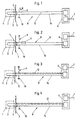
- a wire loop 2 is embedded, which serves as a sensor and which is part of a short circuit. Is the Brake pad worn, it has reached its lowest permissible thickness, so this wire loop 2 separated by a braking process and thus the short circuit open.
- These two extreme values, short circuit on the one hand and more open Circle, on the other hand, can be detected without difficulty and are identified by one Sensor electronics and a regulating and control device connected downstream evaluated.
- This second plug part 4 is fastened to the wheel saddle 5 (FIGS. 5 to 7). Also on Sensor electronics 6 sits on the aforementioned wheel saddle 5, which monitors the speed serves. In order to keep the wiring effort low, that of monitoring the brake pad thickness electronics housed in the same housing like the electronics used to monitor the speed, so that only one Line 7 is required, which leads to the control unit, which is not here is shown and which evaluates the incoming signals via line 7. A such, sensor electronics, which saves wiring effort, or the sensor electronics provided for this purpose Circuit is shown and described in the aforementioned DE 195 04 822 C1.
- a spark gap 9 is in addition to the spark gap mentioned 9 still a high-resistance resistor 11 in which a core 12 of the line 8 is integrated. Because such concentrated components have only small spatial dimensions have, so that it is not excluded that the high static voltage discharges parallel to resistor 11, i.e. jumps over it with a discharge spark, is provided according to another embodiment of FIG. 4, the to form a core 12 of the line 8 as a resistance line, that is to say as a core with extremely high ohmic resistance. In practice, this line 8 is relative in short, it is approx. 10 to 20 cm.
- a spark gap 9 may be connected to one wire 12 (FIG. 3).
- the type of fixing of the plug part is 4 on the wheel saddle 5 not shown in detail. It is shown here, however, that the Spark gap 9 is formed here via the electrode 17 and the wheel saddle 5, the defines the mounting level for the connector part 4, with the spark gap also here can be precisely determined.
- FIG. 7 corresponds to that of FIG. 5, but is here the ground connection of the second wire 16 of the line 8 to the screw sleeve 15 shown.
- the plug 3 is at the ends of the wire loop 2 of the brake pad Not shown. This is only indicated schematically in FIGS. 1 to 4. This connector 3 is inserted into the connector part 4 during assembly.
Landscapes
- Engineering & Computer Science (AREA)
- General Engineering & Computer Science (AREA)
- Mechanical Engineering (AREA)
- Transportation (AREA)
- Braking Arrangements (AREA)
Description
- Die Fig. 1 bis 4
- schematisch nach Art von Blockschaltbildern verschiedene prinzipielle Ausführungsformen der Erfindung;
- die Fig. 5 bis 7
- Querschnitte durch das am Radsattel festgelegte Steckerteil mit in das Steckerteil integrierter Funkenstrecke; in allen Figuren sind gleiche bzw. gleichwertige Teile mit identischen Hinweisziffern versehen.
- 1
- strichlierte Linie
- 2
- Drahtschleife
- 3
- Stecker
- 4
- zweiter Steckerteil
- 5
- Radsattel
- 6
- Sensorelektronik
- 7
- Leitung
- 8
- Leitung
- 9
- Funkenstrecke
- 10
- Masse
- 11
- Widerstand
- 12
- Ader
- 13
- Steckergehäuse
- 14
- Befestigungsschraube
- 15
- Verschraubhülse
- 16
- Ader
- 17
- Elektrode
Claims (7)
- Einrichtung zum Überwachen der Stärke eines Bremsbelages bei einer Kraftfahrzeug-Scheibenbremse, bei welcher im Bremsbelag eine Drahtschleife als Fühler eingebettet ist und die außerhalb des Bremsbelages liegenden Enden der Drahtschleife mit einem Stecker verbunden sind, der mit einem am Radsattel festgelegten zweiten Steckerteil kontaktgebend verbindbar ist und die mit diesem zweiten Steckerteil verbundene Leitung zu einer Sensorelektronik führt, die ihrerseits mit einer elektronischen Steuer- und/oder Regeleinrichtung zur Auswertung der Signale verbunden ist, dadurch gekennzeichnet, daß die zweiadrige, das zweite Steckerteil (4) und die Sensoreletronik (6) verbindende Leitung (8) einen großen Widerstand aufweist und/oder zwischen zumindest einer Ader (12) dieser Leitung (8) und dem Chassis des Kraftfahrzeuges oder dem Radsattel (5) eine Funkenstrecke (9) vorgesehen ist.
- Einrichtung nach Anspruch 1, dadurch gekennzeichnet, daß die Größe des Widerstandes mindestens 100 k Ω oder mehr beträgt.
- Einrichtung nach Anspruch 1 oder 2, dadurch gekennzeichnet, daß mindestens eine der beiden Adern (12) der Leitung (8) als Widerstandsleitung ausgebildet ist (Fig. 3, 4).
- Einrichtung nach Anspruch 1 oder 2, dadurch gekennzeichnet, daß der Widerstand (11) als konzentriertes Bauteil in einer der beiden Adern (12) der Leitung (8) vorgesehen ist (Fig. 2).
- Einrichtung nach einem der Ansprüche 1 bis 4, dadurch gekennzeichnet, daß die den kleinen Widerstand aufweisende Ader (16) der Leitung (8) an Masse (10) angeschlossen ist.
- Einrichtung nach Anspruch 1, dadurch gekennzeichnet, daß eine Elektrode (17) der Funkenstrecke (9) an der den großen Widerstand aufweisenden Ader (12) der Leitung (8) liegt.
- Einrichtung nach Anspruch 1 oder 6, dadurch gekennzeichnet, daß die Funkenstrecke (9) in das am Radsattel (5) vorgesehene Steckerteil (4) integriert ist.
Applications Claiming Priority (2)
| Application Number | Priority Date | Filing Date | Title |
|---|---|---|---|
| DE19642250 | 1996-10-12 | ||
| DE19642250A DE19642250C1 (de) | 1996-10-12 | 1996-10-12 | Einrichtung zum Überwachen der Stärke eines Bremsbelages bei einer Kraftfahrzeug-Scheibenbremse |
Publications (3)
| Publication Number | Publication Date |
|---|---|
| EP0836029A2 EP0836029A2 (de) | 1998-04-15 |
| EP0836029A3 EP0836029A3 (de) | 2000-05-31 |
| EP0836029B1 true EP0836029B1 (de) | 2002-01-09 |
Family
ID=7808649
Family Applications (1)
| Application Number | Title | Priority Date | Filing Date |
|---|---|---|---|
| EP97116457A Expired - Lifetime EP0836029B1 (de) | 1996-10-12 | 1997-09-22 | Einrichtung zum Überwachen der Stärke eines Bremsbelages bei einer Kraftfahrzeug-Scheibenbremse |
Country Status (4)
| Country | Link |
|---|---|
| EP (1) | EP0836029B1 (de) |
| AT (1) | ATE211805T1 (de) |
| DE (2) | DE19642250C1 (de) |
| ES (1) | ES2171799T3 (de) |
Family Cites Families (3)
| Publication number | Priority date | Publication date | Assignee | Title |
|---|---|---|---|---|
| US4606435A (en) * | 1984-09-10 | 1986-08-19 | General Motors Corporation | Brake lining wear sensor and indicator circuit |
| DE4308272C1 (de) * | 1993-03-16 | 1994-06-09 | Mannesmann Kienzle Gmbh | Sensorelement für einen mehrstufigen Verschleißgeber, insbesondere für Bremsbeläge |
| DE19504822C1 (de) * | 1995-02-14 | 1996-09-26 | Hirschmann Richard Gmbh | Einrichtung zum Überwachen von mindestens zwei Zustandsgrößen eines Kraftfahrzeuges |
-
1996
- 1996-10-12 DE DE19642250A patent/DE19642250C1/de not_active Expired - Lifetime
-
1997
- 1997-09-22 AT AT97116457T patent/ATE211805T1/de not_active IP Right Cessation
- 1997-09-22 EP EP97116457A patent/EP0836029B1/de not_active Expired - Lifetime
- 1997-09-22 ES ES97116457T patent/ES2171799T3/es not_active Expired - Lifetime
- 1997-09-22 DE DE59705961T patent/DE59705961D1/de not_active Expired - Fee Related
Also Published As
| Publication number | Publication date |
|---|---|
| DE19642250C1 (de) | 1998-04-09 |
| EP0836029A3 (de) | 2000-05-31 |
| EP0836029A2 (de) | 1998-04-15 |
| ATE211805T1 (de) | 2002-01-15 |
| DE59705961D1 (de) | 2002-02-14 |
| ES2171799T3 (es) | 2002-09-16 |
Similar Documents
| Publication | Publication Date | Title |
|---|---|---|
| DE102007020882B4 (de) | Einrichtung zur Überprüfung der Befestigung einer Leiterbahnplatte an einem Träger | |
| EP1148602B1 (de) | Überspannungsschutzeinrichtung | |
| DE29601998U1 (de) | Modularer Steckverbinder | |
| WO2013037549A1 (de) | Messwiderstand für stromsensor und stromsensoreinheit | |
| EP1135281B1 (de) | Zündvorrichtung für rückhaltemittel in einem fahrzeug | |
| DE19855528A1 (de) | Kapazitiver Spannungsteiler | |
| EP0836029B1 (de) | Einrichtung zum Überwachen der Stärke eines Bremsbelages bei einer Kraftfahrzeug-Scheibenbremse | |
| EP2085785A2 (de) | Vorrichtung zur Strommessung | |
| DE10139202A1 (de) | Elektrischer Verteiler | |
| EP0757796A1 (de) | Vorrichtung zum verbinden eines spannungsanzeigegerätes mit einem sensor | |
| DE4018673C2 (de) | Vorrichtung zum Zünden von Kraftstoff für eine Brennkraftmaschine | |
| EP0233346A1 (de) | Drehzahlsensor einer Gleitschutzanlage für Fahrzeuge | |
| DE3519303C2 (de) | Gleichspannungsgespeister Näherungsschalter | |
| DE10143164B4 (de) | Potentiometer | |
| DE3709943C2 (de) | Kabelendverschluß | |
| DE10156652A1 (de) | Sensor zur orts- und/oder zeitauflösenden Kraft- oder Druckmessung | |
| DE102016224657A1 (de) | Verfahren zum Verbinden eines Bauelementträgers mit einer Leiterplatte und Verbund aus einer Leiterplatte und einem Bauelementträger | |
| DE2234055A1 (de) | Zuendspannungsgeber | |
| DE3119681A1 (de) | In einen motorblock oder dergleichen einsetzbare vorrichtung zur temperaturfuehlung und/oder temperaturabhaengigen schaltung oder dergleichen | |
| DE19849505C2 (de) | Hochspannungsverbindungselement | |
| DE10249143A1 (de) | Sensoranordnung mit 1-Draht-Schnittstelle | |
| DE102004017101A1 (de) | Diagnostizierbare Befestigungsvorrichtung für Elektronikkomponenten und entsprechendes Diagnoseverfahren | |
| DE202013001992U1 (de) | Sensormodul zur Lichtbogenerkennung in Fahrzeugen | |
| DE1962923C3 (de) | Vorrichtung zum Ermitteln von Spänen in flüssigen oder gasförmigen Medien (Spanwächter) | |
| DE3835757C3 (de) | Elektrohydraulisches Steuergerät |
Legal Events
| Date | Code | Title | Description |
|---|---|---|---|
| PUAI | Public reference made under article 153(3) epc to a published international application that has entered the european phase |
Free format text: ORIGINAL CODE: 0009012 |
|
| AK | Designated contracting states |
Kind code of ref document: A2 Designated state(s): AT DE ES FR GB IT |
|
| AX | Request for extension of the european patent |
Free format text: AL;LT;LV;RO;SI |
|
| PUAL | Search report despatched |
Free format text: ORIGINAL CODE: 0009013 |
|
| AK | Designated contracting states |
Kind code of ref document: A3 Designated state(s): AT BE CH DE DK ES FI FR GB GR IE IT LI LU MC NL PT SE |
|
| AX | Request for extension of the european patent |
Free format text: AL;LT;LV;RO;SI |
|
| 17P | Request for examination filed |
Effective date: 20000824 |
|
| GRAG | Despatch of communication of intention to grant |
Free format text: ORIGINAL CODE: EPIDOS AGRA |
|
| 17Q | First examination report despatched |
Effective date: 20001116 |
|
| AKX | Designation fees paid |
Free format text: AT DE ES FR GB IT |
|
| GRAG | Despatch of communication of intention to grant |
Free format text: ORIGINAL CODE: EPIDOS AGRA |
|
| GRAH | Despatch of communication of intention to grant a patent |
Free format text: ORIGINAL CODE: EPIDOS IGRA |
|
| RAP1 | Party data changed (applicant data changed or rights of an application transferred) |
Owner name: HIRSCHMANN AUSTRIA GMBH |
|
| GRAH | Despatch of communication of intention to grant a patent |
Free format text: ORIGINAL CODE: EPIDOS IGRA |
|
| GRAA | (expected) grant |
Free format text: ORIGINAL CODE: 0009210 |
|
| REG | Reference to a national code |
Ref country code: GB Ref legal event code: IF02 |
|
| AK | Designated contracting states |
Kind code of ref document: B1 Designated state(s): AT DE ES FR GB IT |
|
| REF | Corresponds to: |
Ref document number: 211805 Country of ref document: AT Date of ref document: 20020115 Kind code of ref document: T |
|
| REF | Corresponds to: |
Ref document number: 59705961 Country of ref document: DE Date of ref document: 20020214 |
|
| GBT | Gb: translation of ep patent filed (gb section 77(6)(a)/1977) |
Effective date: 20020411 |
|
| ET | Fr: translation filed | ||
| PGFP | Annual fee paid to national office [announced via postgrant information from national office to epo] |
Ref country code: AT Payment date: 20020827 Year of fee payment: 6 |
|
| REG | Reference to a national code |
Ref country code: ES Ref legal event code: FG2A Ref document number: 2171799 Country of ref document: ES Kind code of ref document: T3 |
|
| PLBE | No opposition filed within time limit |
Free format text: ORIGINAL CODE: 0009261 |
|
| STAA | Information on the status of an ep patent application or granted ep patent |
Free format text: STATUS: NO OPPOSITION FILED WITHIN TIME LIMIT |
|
| 26N | No opposition filed | ||
| PG25 | Lapsed in a contracting state [announced via postgrant information from national office to epo] |
Ref country code: AT Free format text: LAPSE BECAUSE OF NON-PAYMENT OF DUE FEES Effective date: 20030922 |
|
| REG | Reference to a national code |
Ref country code: FR Ref legal event code: CD Ref country code: FR Ref legal event code: CA |
|
| PGFP | Annual fee paid to national office [announced via postgrant information from national office to epo] |
Ref country code: FR Payment date: 20050823 Year of fee payment: 9 |
|
| PGFP | Annual fee paid to national office [announced via postgrant information from national office to epo] |
Ref country code: GB Payment date: 20050912 Year of fee payment: 9 |
|
| PGFP | Annual fee paid to national office [announced via postgrant information from national office to epo] |
Ref country code: ES Payment date: 20050921 Year of fee payment: 9 |
|
| PG25 | Lapsed in a contracting state [announced via postgrant information from national office to epo] |
Ref country code: IT Free format text: LAPSE BECAUSE OF NON-PAYMENT OF DUE FEES Effective date: 20050922 |
|
| GBPC | Gb: european patent ceased through non-payment of renewal fee |
Effective date: 20060922 |
|
| REG | Reference to a national code |
Ref country code: FR Ref legal event code: ST Effective date: 20070531 |
|
| PG25 | Lapsed in a contracting state [announced via postgrant information from national office to epo] |
Ref country code: GB Free format text: LAPSE BECAUSE OF NON-PAYMENT OF DUE FEES Effective date: 20060922 |
|
| REG | Reference to a national code |
Ref country code: ES Ref legal event code: FD2A Effective date: 20060923 |
|
| PG25 | Lapsed in a contracting state [announced via postgrant information from national office to epo] |
Ref country code: ES Free format text: LAPSE BECAUSE OF NON-PAYMENT OF DUE FEES Effective date: 20060923 |
|
| PG25 | Lapsed in a contracting state [announced via postgrant information from national office to epo] |
Ref country code: FR Free format text: LAPSE BECAUSE OF NON-PAYMENT OF DUE FEES Effective date: 20061002 |
|
| PGFP | Annual fee paid to national office [announced via postgrant information from national office to epo] |
Ref country code: DE Payment date: 20080919 Year of fee payment: 12 |
|
| PG25 | Lapsed in a contracting state [announced via postgrant information from national office to epo] |
Ref country code: DE Free format text: LAPSE BECAUSE OF NON-PAYMENT OF DUE FEES Effective date: 20100401 |