EP0836026A2 - Elektromagnetische Kupplung - Google Patents
Elektromagnetische Kupplung Download PDFInfo
- Publication number
- EP0836026A2 EP0836026A2 EP97308032A EP97308032A EP0836026A2 EP 0836026 A2 EP0836026 A2 EP 0836026A2 EP 97308032 A EP97308032 A EP 97308032A EP 97308032 A EP97308032 A EP 97308032A EP 0836026 A2 EP0836026 A2 EP 0836026A2
- Authority
- EP
- European Patent Office
- Prior art keywords
- annular disc
- rotor
- side annular
- electromagnetic clutch
- disc
- Prior art date
- Legal status (The legal status is an assumption and is not a legal conclusion. Google has not performed a legal analysis and makes no representation as to the accuracy of the status listed.)
- Withdrawn
Links
Images


Classifications
-
- F—MECHANICAL ENGINEERING; LIGHTING; HEATING; WEAPONS; BLASTING
- F16—ENGINEERING ELEMENTS AND UNITS; GENERAL MEASURES FOR PRODUCING AND MAINTAINING EFFECTIVE FUNCTIONING OF MACHINES OR INSTALLATIONS; THERMAL INSULATION IN GENERAL
- F16D—COUPLINGS FOR TRANSMITTING ROTATION; CLUTCHES; BRAKES
- F16D27/00—Magnetically- or electrically- actuated clutches; Control or electric circuits therefor
- F16D27/10—Magnetically- or electrically- actuated clutches; Control or electric circuits therefor with an electromagnet not rotating with a clutching member, i.e. without collecting rings
- F16D27/108—Magnetically- or electrically- actuated clutches; Control or electric circuits therefor with an electromagnet not rotating with a clutching member, i.e. without collecting rings with axially movable clutching members
- F16D27/112—Magnetically- or electrically- actuated clutches; Control or electric circuits therefor with an electromagnet not rotating with a clutching member, i.e. without collecting rings with axially movable clutching members with flat friction surfaces, e.g. discs
-
- F—MECHANICAL ENGINEERING; LIGHTING; HEATING; WEAPONS; BLASTING
- F16—ENGINEERING ELEMENTS AND UNITS; GENERAL MEASURES FOR PRODUCING AND MAINTAINING EFFECTIVE FUNCTIONING OF MACHINES OR INSTALLATIONS; THERMAL INSULATION IN GENERAL
- F16D—COUPLINGS FOR TRANSMITTING ROTATION; CLUTCHES; BRAKES
- F16D27/00—Magnetically- or electrically- actuated clutches; Control or electric circuits therefor
- F16D2027/007—Bias of an armature of an electromagnetic clutch by flexing of substantially flat springs, e.g. leaf springs
Definitions
- This invention relates to an electromagnetic clutch, and more particularly to an electromagnetic clutch for transmitting driving force from a drive source to a drive shaft of a refrigerant compressor.
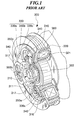
- FIG. 1 is a perspective view, partly in section, of a conventional electromagnetic clutch.
- the electromagnetic clutch 300 includes a hub 310 having a flange portion 311 and rigidly fitted on a drive shaft 302 of a refrigerant compressor, a rotor 320 driven by torque from an engine (not shown) for rotation about the drive shaft 302, an armature plate 330 which is magnetically attracted into abutment with the rotor 320 when a magnetic coil 321 arranged in the rotor 320 is energized, and three leaf springs 340 interposed between the flange portion 311 of the hub 310 and the armature plate 330 for returning the armature plate 330 to its off position when the magnetic coil 321 is deenergized.
- the armature plate 330 is comprised of an outer disk 330a and an inner disk 330b joined to an inner periphery of the outer disk 330a via a jointing metal 330c.
- the rotor 320 has a pulley groove 360 circumferentially formed in its outer peripheral surface, and a V-belt, not shown, extends around the pulley groove 360, for connecting the rotor 320 to a crankshaft of the engine, not shown.
- Rubber stoppers 350a, 350b and 350c are provided respectively between the leaf springs 340 and the inner disk 330b of the armature plate 330 such that they have preloads which prevent rattle.
- the leaf springs 340 having resilient properties hold the armature plate 330 in its off position at a predetermined distance from a friction surface of the rotor 320, whereby driving force of the engine is inhibited from being transmitted to the refrigerant compressor, and hence the rotor 320 rotates in a disconnected state or idles.
- the armature plate 330 is magnetically attracted into abutment with the friction surface of the rotor 320 against the pulling or returning force of the leaf springs 340, whereby the driving force from the engine is transmitted to the drive shaft 302 of the refrigerant compressor.
- the present invention provides an electromagnetic clutch including a hub rigidly fitted on a drive shaft, the hub having a flange portion, a rotor which rotates about the drive shaft, a magnetic coil arranged in the rotor, an armature plate which is magnetically attracted into abutment with the rotor when the magnetic coil is energized, and a plurality of spring members interposed between the flange portion of the hub and the armature plate along a circumference of the rotor, for connection between the flange portion of the hub and the armature plate.
- the electromagnetic clutch according to the invention is characterized in that the armature plate comprises:
- the rotor-side annular disk and the spring-side annular disk are joined to each other via the elastic body. Therefore, when the armature plate receives a variation in torque (reaction force) from the compressor, the variation in the torque is accommodated not only by the spring members but also by the elastic body, which makes it possible to reduce the variation in the torque to a much lower level than a level attained by the prior art.
- the rotor-side annular disk comprises a first annular disk axially opposed to the rotor with the predetermined axial gap therebetween, and a second annular disk connected to the first annular disk in a manner axially opposed to the first annular disk with a predetermined axial gap therebetween, the elastic body being interposed between the second annular disk and the spring-side annular disk in a manner such that the elastic body is axially joined to the second annular disk and the spring-side annular disk.
- the second annular disk has through holes axially formed therethrough at circumferentially-spaced intervals, through which respective portions of the elastic body are in contact with the first annular disk.
- the second annular disk when the armature plate is magnetically attracted into abutment with the rotor, the second annular disk applies an impact on the first annular disk via the portions of the elastic body, whereby noise resulting from the attraction of the armature plate can be reduced.
- the first annular disk has projections formed on a second annular disk-side surface thereof for producing the predetermined axial gap between the first annular disk and the second annular disk.
- the projections define therein through holes, respectively, which extend axially, the first annular disk and the second annular disk being connected by a plurality of rivets, the rivets extending through the through holes of the projections, respectively.
- the elastic body is formed of rubber and joined to the second annular disk and the spring-side annular disk by vulcanizing adhesion.
- the first annular disk comprises an outer disk, and an inner disk arranged radially inward of the outer disk with a predetermined radial gap therebetween.
- the radial gap is provided between the two disks, magnetic flux is prevented from leaking via the rotor and the armature plate, which improves the attraction efficiency of the armature plate.
- the rotor-side annular disk is formed by a single disk, the elastic body being integrally sandwiched between the rotor-side annular disk and the spring-side annular disk.
- the armature plate when the armature plate is magnetically attracted into abutment with the rotor, the torque from the rotor is transmitted to the rotor-side annular disk, the elastic body, the spring-side annular disk, the spring members, and the flange portion of the hub, in the mentioned order, to cause rotation of the drive shaft of the compressor. Therefore, when the armature plate receives a variation in torque (reaction force) from the compressor, the variation in the torque is accommodated not only by the spring members but also by the elastic body. Further, according to this construction, the armature plate has only two disks, which makes it possible to reduce the axial length of the electromagnetic clutch.
- the elastic body is formed of rubber and joined to the rotor-side annular disk and the spring-side annular disk by baking.
- the rotor-side annular disk comprises an outer disk, and an inner disk arranged radially inward of the outer disk with a predetermined radial gap therebetween.
- FIG. 2 is a longitudinal cross-sectional view showing the arrangement of an electromagnetic clutch according to a first embodiment of the invention.
- FIG. 3 is a plan view of an armature plate of the FIG. 2 electromagnetic clutch, and
- FIG. 4 a cross-sectional view taken on line IV-IV of FIG. 3.
- the electromagnetic clutch 1 includes a hub 10 having a flange portion 11 and rigidly fitted on a drive shaft 2 of a refrigerant compressor, a rotor 20 driven by torque from an engine (not shown) for rotation about the drive shaft 2, an armature plate 30 which is magnetically attracted into abutment with the rotor 20 when a magnetic coil 21 arranged within the rotor 20 is energized, and three leaf springs 40 interposed between the flange portion 11 of the hub 10 and the armature plate 30 for returning the armature plate 30 to its off position when the magnetic coil 21 is deenergized.
- the armature plate 30 is comprised of a first annular disk 30a, a second annular disk 30b, an elastic body 30c, and a third annular disk 30d.
- the first annular disk 30a which is comprised of an outer disk 31, and an inner disk 33 arranged radially inward of the outer disk 31 with a radial gap 32 therebetween, is arranged in a manner axially opposed to the rotor 20.
- the outer disk 31 and the inner disk 33 have through holes 31a and through holes 33a axially formed therethrough, respectively, at angular intervals of 120 degrees about the rotation axis of the electromagnetic clutch (i.e. the common rotation axis of the outer and inner disks 31, 33).
- the first annular disk 30a has recesses each formed at a rotor-side end of each through hole 31a or 33a for accommodating a head of each rivet 16 or 17, referred to hereinafter, such that the first annular disk 30a can be brought into surface contact with an end face of the rotor 20 when the armature plate 30 is magnetically attracted into abutment with the rotor 20 (see FIG. 2).
- the second annular disk 30b which has approximately the same radial width as that of the first annular disk 30a (including the outer disk 31, the radial gap 32, and the inner disk 33) , is arranged in a manner axially opposed to the first annular disk 30a.
- the second annular disk 30b is formed with through holes 31b corresponding respectively to the through holes 31a of the outer disk 31 and through holes 33b corresponding respectively to the through holes 33a of the inner disk 33.
- the through holes 31b and the through holes 33b are formed at respective angular intervals of 120 degrees about the rotation axis of the second annular disk 30b.
- the first annular disk 30a has annular projections 30f and 30g formed on a second annular disk-side end face thereof at respective locations corresponding to the through holes 31b and 33b, for producing an axial gap 30e through which heat generated on the armature plate 30 when the armature plate 30 is in friction contact with the rotor 20 is dissipated.
- the annular projections 30f and 30g each define therein a through hole continuous with a corresponding one of the through holes 31a and 33a in a manner concentric with a corresponding one of the through holes 31b and 33b of the second annular disk 30b.
- annular projections 30f, 30g are formed on the first annular disk 30a, this is not limitative, but a washer or the like may be interposed between the first annular disk 30a and the second annular disk 30b.
- the third annular disk 30d having approximately the same radial width as that of the first annular disk 30a (including the outer disk 31, the radial gap 32 and the inner disk 33) has through holes 31d axially formed therethrough at angular intervals of 120 degrees about the rotation axis thereof (i.e. the rotation axis of the electromagnetic clutch).
- the elastic body 30c is formed by a rubber member having substantially the same shape as that of the third annular disk 30d.
- This rubber member which is bonded to the second annular disk 30b and the third annular disk 30d by vulcanizing adhesion, is superior to the leaf springs 40 in capability of accommodating the variation in the torque (reaction force) from the refrigerant compressor.
- the three leaf springs (spring members) 40 each include an annular portion 41 having a generally circular periphery.
- the annular portion 41 has three through holes 41a, 42a, and 42b axially formed therethrough in a manner radially aligned to the rotation axis of the electromagnetic clutch.
- the flange portion 11 of the hub 10 is generally circular in outer shape and has through holes lla axially formed therethrough on an identical circumferential line at angular intervals of 120 degrees about the longitudinal or rotation axis of the drive shaft 2 (i.e. the rotation axis of the electromagnetic clutch).
- the leaf springs 40 and the flange portion 11 are connected by rivets 14 extending respectively through corresponding ones of the through holes 42a of the leaf springs 40 and corresponding ones of the through holes 11a of the flange portion 11, whereby portions of the leaf springs 40 are fixed to the bottom or the rotor-side surface of the flange portion 11.
- the leaf springs 40 and the third annular disk 30d are connected by rivets 15 extending respectively through corresponding ones of the through holes 41a of the leaf springs 40 and corresponding ones of the through holes 31d of the third annular disk 30d, which correspond in location to the outer disk 31 of the first annular disk 30a, whereby portions of the leaf springs 40 are fixed to the top or spring-side surface of the third annular disk 30d.
- Rubber stoppers 50a to 50c are press-fitted into the through holes 42b of the leaf springs 40, respectively.
- the rubber stoppers 50a to 50c are in urging contact at respective one ends thereof with the top or spring-side surface of the third annular disk 30d such that they have preloads which prevent rattle from occurring between the armature plate 30 and the leaf springs 40.
- first annular disk 30a and the second annular disk 30b are connected by the aforementioned rivets 16 extending through corresponding ones of the through holes 31a of the outer disk 31, corresponding ones of the through holes of the annular projections 30f, and corresponding ones of the through holes 31b of the second annular disk 30b, and the aforementioned rivets 17 extending through corresponding ones of the through holes 33a of the inner disk 33, corresponding ones of the through holes of the annular projections 30g, and corresponding ones of the through holes 33b of the second annular disk 30b, whereby the first annular disk 30a and the second annular disk 30b are secured to each other with the predetermined axial gap 30e provided therebetween.
- the electromagnetic clutch of the present embodiment when the armature plate 30 is magnetically attracted into abutment with the rotor 20 when the magnetic coil 21 is energized, torque from the engine is transmitted to the first annular disk 30a, the rivets 16, 17, the second annular disk 30b, the elastic body 30c, the third annular disk 30d, the leaf springs 40, and the flange portion 11 of the hub 10, in the mentioned order, to cause rotation of the drive shaft 2 of the refrigerant compressor for driving the refrigerant compressor.
- the armature plate 30 is constructed as a double disk device in such a manner that the outer and inner disks 31 and 33 of the first annular disk 30a are secured to the second annular disk 30b by the rivets 16 and 17, respectively, with the radial gap 32 provided therebetween, so that magnetic flux is prevented from leaking via the rotor 20 and the armature plate 30, which improves the attraction efficiency of the armature plate 30.
- the variation in the torque is accommodated first by elastic deformation of the elastic body 30c, and then the remainder, which was not accommodated by the elastic body 30c, is accommodated by elastic deformation or deflection of the leaf springs 40.
- the torque or reaction force from the compressor is reduced by both the elastic body 30c and the leaf springs 40, which makes it possible to decrease load or burden resulting from the variation in the torque, which is imposed on component parts (such as the leaf springs 40) of the electromagnetic clutch.
- FIG. 5 is a plan view of an armature plate of an electromagnetic clutch according to a variation of the first embodiment of the invention.
- FIG. 6 is a view taken on line VI-VI of FIG. 5, and
- FIG. 7 a view taken on line VII-VII of the same.
- Component parts and elements corresponding to those of the first embodiment are designated by identical reference numerals, and description thereof is omitted.
- This variation is distinguished from the first embodiment in that the second annular disk 30b has a plurality of arcuate slits 231, 233 axially formed therethrough at circumferentially-spaced intervals about the rotation axis thereof and that portions of the elastic body 30c extend respectively through the slits 231, 233 such that they slightly project from the second annular disk 30b into urging contact with the first annular disk 30a.
- the present variation provides the same effects as obtained by the first embodiment. Further, since the elastic body 30c is always pressed against the first annular disk 30a, noise produced when the armature plate 30 is magnetically attracted into abutment with the rotor 20 is absorbed by the elastic body 30c having elasticity, whereby the noise is reduced.
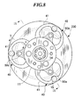
- FIG. 8 is a plan view of an armature plate of an electromagnetic clutch according to a second embodiment of the invention.
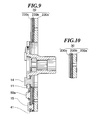
- FIG. 9 is a view taken on line IX-IX of FIG. 8, and
- FIG. 10 a view taken on line X-X of the same.
- Component parts and elements corresponding to those of the first embodiment are designated by identical reference numerals, and description thereof is omitted.
- the armature plate 230 is comprised of a rotor-side annular disk 230a axially opposed to the rotor 20 (see FIG. 2) with a predetermined axial gap therebetween, an elastic body 230b, and a spring-side annular disk 230c axially joined to the rotor-side annular disk 230a via the elastic body 230b.
- the present embodiment is distinguished from the first embodiment, in which the second annular disk 30b is connected to the first annular disk 30a (equivalent to the rotor-side annular disk 230a) by the rivets 16, 17, in that the second annular disk 30b is dispensed with and that the elastic body 230b is bonded to the rotor-side annular disk 230a and the spring-side annular disk 230c by baking in a manner integrally sandwiched therebetween.
- This embodiment provides the same effects as obtained by the first embodiment. Further, since the second annular disk 30b and the rivets 16, 17 are not used, it is possible to provide an electromagnetic clutch having a reduced axial length in comparison with the electromagnetic clutch according to the first embodiment.
Landscapes
- Engineering & Computer Science (AREA)
- General Engineering & Computer Science (AREA)
- Physics & Mathematics (AREA)
- Electromagnetism (AREA)
- Mechanical Engineering (AREA)
- Compressors, Vaccum Pumps And Other Relevant Systems (AREA)
- Hydraulic Clutches, Magnetic Clutches, Fluid Clutches, And Fluid Joints (AREA)
- Air-Conditioning For Vehicles (AREA)
Applications Claiming Priority (3)
| Application Number | Priority Date | Filing Date | Title |
|---|---|---|---|
| JP8289331A JPH10115333A (ja) | 1996-10-11 | 1996-10-11 | 電磁クラッチ |
| JP289331/96 | 1996-10-11 | ||
| JP28933196 | 1996-10-11 |
Publications (2)
| Publication Number | Publication Date |
|---|---|
| EP0836026A2 true EP0836026A2 (de) | 1998-04-15 |
| EP0836026A3 EP0836026A3 (de) | 1999-09-22 |
Family
ID=17741819
Family Applications (1)
| Application Number | Title | Priority Date | Filing Date |
|---|---|---|---|
| EP97308032A Withdrawn EP0836026A3 (de) | 1996-10-11 | 1997-10-10 | Elektromagnetische Kupplung |
Country Status (5)
| Country | Link |
|---|---|
| US (1) | US5944158A (de) |
| EP (1) | EP0836026A3 (de) |
| JP (1) | JPH10115333A (de) |
| KR (1) | KR100281730B1 (de) |
| CN (1) | CN1180799A (de) |
Cited By (6)
| Publication number | Priority date | Publication date | Assignee | Title |
|---|---|---|---|---|
| FR2775503A1 (fr) * | 1998-02-27 | 1999-09-03 | Dana Corp | Ensemble d'induit amortissant les bruits pour un accouplement electromagnetique |
| EP1167798A3 (de) * | 2000-06-30 | 2002-01-16 | Mitsubishi Heavy Industries, Ltd. | Elektromagnetische Kupplung und damit ausgerüsteter Kompressor |
| EP1184586A1 (de) * | 2000-08-31 | 2002-03-06 | Mitsubishi Heavy Industries, Ltd. | Elektromagnetische Kupplung und Kompressor mit elektromagnetischer Kupplung |
| EP1486694A3 (de) * | 2003-06-10 | 2005-06-01 | Halla Climate Control Corporation | Scheiben- Nabenanordnung für elektromagnetische Kupplung in einem Kompressor |
| WO2011047807A1 (de) * | 2009-10-19 | 2011-04-28 | Kendrion Linnig Gmbh | Vorrichtung zur schwingungsdämpfung in einem getriebe |
| EP3141772A3 (de) * | 2015-09-09 | 2017-03-29 | Ogura Clutch Co., Ltd. | Elektromagnetische kupplung |
Families Citing this family (14)
| Publication number | Priority date | Publication date | Assignee | Title |
|---|---|---|---|---|
| EP0957278A4 (de) * | 1997-12-01 | 2000-10-25 | Toyoda Automatic Loom Works | Mechanismus zur energieübertragung |
| JP4174896B2 (ja) * | 1998-09-22 | 2008-11-05 | 株式会社デンソー | 電磁クラッチ |
| KR100423327B1 (ko) * | 2001-12-03 | 2004-03-18 | 현대자동차주식회사 | 자동차용 에어컨 컴프레서의 클러치 구조 |
| JP3985705B2 (ja) * | 2003-03-24 | 2007-10-03 | 株式会社デンソー | 電磁クラッチ |
| JP2005233338A (ja) * | 2004-02-20 | 2005-09-02 | Denso Corp | 電磁クラッチ |
| JP4713293B2 (ja) * | 2005-10-07 | 2011-06-29 | サンデン株式会社 | 圧縮機 |
| DE102006056293A1 (de) * | 2005-12-22 | 2007-06-28 | Luk Lamellen Und Kupplungsbau Beteiligungs Kg | Mehrteilige Antriebsscheibe |
| JP2008095704A (ja) * | 2006-10-05 | 2008-04-24 | Aisin Seiki Co Ltd | 電磁連結装置 |
| DE102008002711A1 (de) * | 2008-06-17 | 2009-12-24 | Zf Friedrichshafen Ag | Antriebsplatte für eine Kopplungseinrichtung, insbesondere hydrodynamischer Drehmomentwandler |
| JP4985749B2 (ja) * | 2009-11-30 | 2012-07-25 | 株式会社デンソー | クラッチ機構 |
| JP5451578B2 (ja) * | 2010-11-05 | 2014-03-26 | 小倉クラッチ株式会社 | 電磁クラッチ |
| JP6645415B2 (ja) * | 2016-12-16 | 2020-02-14 | 株式会社デンソー | 動力伝達装置 |
| KR102590950B1 (ko) * | 2017-06-28 | 2023-10-19 | 한온시스템 주식회사 | 클러치 및 이를 포함하는 압축기 |
| US11873868B2 (en) * | 2020-05-14 | 2024-01-16 | Horton, Inc. | Valve control system for viscous friction clutch |
Family Cites Families (8)
| Publication number | Priority date | Publication date | Assignee | Title |
|---|---|---|---|---|
| US3565223A (en) * | 1969-06-09 | 1971-02-23 | Pitts Ind Inc | Resilient lining for magnetic clutch |
| US4227600A (en) * | 1977-10-18 | 1980-10-14 | Sankyo Electric Company Limited | Electromagnetic clutches |
| US4445606A (en) * | 1981-12-14 | 1984-05-01 | Warner Electric Brake & Clutch Company | Armature assembly for electromagnetic coupling |
| JPS60205026A (ja) * | 1984-03-28 | 1985-10-16 | Ogura Clutch Co Ltd | 電磁連結装置 |
| US5036964A (en) * | 1990-03-28 | 1991-08-06 | Dana Corporation | Armature assembly for an electromagnetic coupling |
| US5138293A (en) * | 1990-09-17 | 1992-08-11 | Ogura Clutch, Co., Ltd. | Terminal connection structure of electromagnetic coupling device |
| US5372228A (en) * | 1993-03-04 | 1994-12-13 | Dana Corporation | Sound-damping armature assembly for an electromagnetic coupling |
| US5642798A (en) * | 1996-03-22 | 1997-07-01 | General Motors Corporation | Electromagentic compressor clutch with combined torque cushion and armature cooling |
-
1996
- 1996-10-11 JP JP8289331A patent/JPH10115333A/ja not_active Withdrawn
-
1997
- 1997-10-06 US US08/944,731 patent/US5944158A/en not_active Expired - Fee Related
- 1997-10-08 KR KR1019970051619A patent/KR100281730B1/ko not_active Expired - Fee Related
- 1997-10-10 EP EP97308032A patent/EP0836026A3/de not_active Withdrawn
- 1997-10-10 CN CN97120052A patent/CN1180799A/zh active Pending
Cited By (12)
| Publication number | Priority date | Publication date | Assignee | Title |
|---|---|---|---|---|
| FR2775503A1 (fr) * | 1998-02-27 | 1999-09-03 | Dana Corp | Ensemble d'induit amortissant les bruits pour un accouplement electromagnetique |
| US6194803B1 (en) | 1998-02-27 | 2001-02-27 | Warner Electric Technology, Inc. | Sound damping armature assembly for an electromagnetic coupling |
| US6591477B1 (en) | 1998-02-27 | 2003-07-15 | Warner Electric Technology, Inc. | Method for making an armature assembly |
| EP1167798A3 (de) * | 2000-06-30 | 2002-01-16 | Mitsubishi Heavy Industries, Ltd. | Elektromagnetische Kupplung und damit ausgerüsteter Kompressor |
| US6568520B2 (en) | 2000-06-30 | 2003-05-27 | Mitsubishi Heavy Industries, Ltd. | Electromagnetic clutch and compressor equipped therewith |
| EP1184586A1 (de) * | 2000-08-31 | 2002-03-06 | Mitsubishi Heavy Industries, Ltd. | Elektromagnetische Kupplung und Kompressor mit elektromagnetischer Kupplung |
| AU755604B2 (en) * | 2000-08-31 | 2002-12-19 | Mitsubishi Heavy Industries, Ltd. | Electromagnetic clutch and a compressor provided with electromagnetic clutch |
| US6578689B2 (en) | 2000-08-31 | 2003-06-17 | Mitsubishi Heavy Industries, Ltd. | Electromagnetic clutch and a compressor provided with electromagnetic clutch |
| EP1486694A3 (de) * | 2003-06-10 | 2005-06-01 | Halla Climate Control Corporation | Scheiben- Nabenanordnung für elektromagnetische Kupplung in einem Kompressor |
| US7044284B2 (en) | 2003-06-10 | 2006-05-16 | Halla Climate Control Corporation | Disc and hub assembly for electromagnetic clutch in a compressor |
| WO2011047807A1 (de) * | 2009-10-19 | 2011-04-28 | Kendrion Linnig Gmbh | Vorrichtung zur schwingungsdämpfung in einem getriebe |
| EP3141772A3 (de) * | 2015-09-09 | 2017-03-29 | Ogura Clutch Co., Ltd. | Elektromagnetische kupplung |
Also Published As
| Publication number | Publication date |
|---|---|
| JPH10115333A (ja) | 1998-05-06 |
| KR19980032657A (ko) | 1998-07-25 |
| EP0836026A3 (de) | 1999-09-22 |
| CN1180799A (zh) | 1998-05-06 |
| KR100281730B1 (ko) | 2001-03-02 |
| US5944158A (en) | 1999-08-31 |
Similar Documents
| Publication | Publication Date | Title |
|---|---|---|
| US5944158A (en) | Electromagnetic clutch | |
| US6026944A (en) | Wet multi-plate clutch | |
| US4828090A (en) | Electromagnetic clutch | |
| US5195625A (en) | Torque cushion for electromagnetic clutch | |
| JP2752897B2 (ja) | 電磁連結装置 | |
| US5184705A (en) | Electromagnetic clutch | |
| EP0841497A2 (de) | Elektromagnetische Kupplung | |
| US5150779A (en) | Armature assembly for an electromagnetic coupling | |
| US5059842A (en) | Electromagnetic clutch with grooved friction surface | |
| US20040188217A1 (en) | Electromagnetic clutch | |
| JP3605876B2 (ja) | 動力断続機 | |
| US5390774A (en) | Electromagnetic clutch with improved guidance and retention | |
| JP4271571B2 (ja) | ブレーキングおよびクラッチングデバイスを組み合わせた摩擦部材 | |
| KR100300390B1 (ko) | 압축기용클러치 | |
| EP0339431B1 (de) | Elektromagnetisch betätigte Kupplung | |
| US5632366A (en) | Electromagnetic clutch with improved torque cushion | |
| JP4524668B2 (ja) | 電磁クラッチ用カップリング | |
| US6578688B2 (en) | Spline cushion clutch driver for an electromagnetic clutch | |
| EP0216451A2 (de) | Angetriebene Kupplungsplatte | |
| KR200147748Y1 (ko) | 압축기용 클러치 | |
| US4923045A (en) | Clutch disc having an integral annulus of friction material | |
| KR100658989B1 (ko) | 압축기의전자클러치 | |
| JPS5926104Y2 (ja) | 電磁クラッチ | |
| JPS5923868Y2 (ja) | 電磁クラッチ | |
| JPH0417868Y2 (de) |
Legal Events
| Date | Code | Title | Description |
|---|---|---|---|
| PUAI | Public reference made under article 153(3) epc to a published international application that has entered the european phase |
Free format text: ORIGINAL CODE: 0009012 |
|
| AK | Designated contracting states |
Kind code of ref document: A2 Designated state(s): DE FR |
|
| AX | Request for extension of the european patent |
Free format text: AL;LT;LV;RO;SI |
|
| PUAL | Search report despatched |
Free format text: ORIGINAL CODE: 0009013 |
|
| AK | Designated contracting states |
Kind code of ref document: A3 Designated state(s): AT BE CH DE DK ES FI FR GB GR IE IT LI LU MC NL PT SE |
|
| AX | Request for extension of the european patent |
Free format text: AL;LT;LV;RO;SI |
|
| AKX | Designation fees paid |
Free format text: DE FR |
|
| STAA | Information on the status of an ep patent application or granted ep patent |
Free format text: STATUS: THE APPLICATION IS DEEMED TO BE WITHDRAWN |
|
| 18D | Application deemed to be withdrawn |
Effective date: 20000323 |