EP0834949A2 - Laminated structures of sintered ceramic material, electrochemical cells, filters and process for producing such sintered laminated structures - Google Patents
Laminated structures of sintered ceramic material, electrochemical cells, filters and process for producing such sintered laminated structures Download PDFInfo
- Publication number
- EP0834949A2 EP0834949A2 EP97307578A EP97307578A EP0834949A2 EP 0834949 A2 EP0834949 A2 EP 0834949A2 EP 97307578 A EP97307578 A EP 97307578A EP 97307578 A EP97307578 A EP 97307578A EP 0834949 A2 EP0834949 A2 EP 0834949A2
- Authority
- EP
- European Patent Office
- Prior art keywords
- ceramic
- electrochemical cell
- solid electrolyte
- substrate
- cell
- Prior art date
- Legal status (The legal status is an assumption and is not a legal conclusion. Google has not performed a legal analysis and makes no representation as to the accuracy of the status listed.)
- Granted
Links
- 229910010293 ceramic material Inorganic materials 0.000 title claims abstract description 6
- 238000000034 method Methods 0.000 title claims description 17
- 230000008569 process Effects 0.000 title claims description 15
- 239000000919 ceramic Substances 0.000 claims abstract description 77
- 239000007784 solid electrolyte Substances 0.000 claims description 63
- 239000000758 substrate Substances 0.000 claims description 63
- 239000000463 material Substances 0.000 claims description 17
- 238000010304 firing Methods 0.000 claims description 16
- 238000001914 filtration Methods 0.000 claims description 11
- 239000010408 film Substances 0.000 description 64
- 230000000052 comparative effect Effects 0.000 description 33
- 239000000446 fuel Substances 0.000 description 33
- 239000007789 gas Substances 0.000 description 30
- PXHVJJICTQNCMI-UHFFFAOYSA-N Nickel Chemical compound [Ni] PXHVJJICTQNCMI-UHFFFAOYSA-N 0.000 description 22
- 238000005868 electrolysis reaction Methods 0.000 description 21
- 239000007787 solid Substances 0.000 description 21
- 239000011812 mixed powder Substances 0.000 description 19
- XLYOFNOQVPJJNP-UHFFFAOYSA-N water Substances O XLYOFNOQVPJJNP-UHFFFAOYSA-N 0.000 description 19
- MCMNRKCIXSYSNV-UHFFFAOYSA-N Zirconium dioxide Chemical compound O=[Zr]=O MCMNRKCIXSYSNV-UHFFFAOYSA-N 0.000 description 18
- 238000012360 testing method Methods 0.000 description 18
- 239000001257 hydrogen Substances 0.000 description 17
- 229910052739 hydrogen Inorganic materials 0.000 description 17
- 239000011230 binding agent Substances 0.000 description 15
- UFHFLCQGNIYNRP-UHFFFAOYSA-N Hydrogen Chemical compound [H][H] UFHFLCQGNIYNRP-UHFFFAOYSA-N 0.000 description 14
- 239000000843 powder Substances 0.000 description 14
- NFYLSJDPENHSBT-UHFFFAOYSA-N chromium(3+);lanthanum(3+);oxygen(2-) Chemical compound [O-2].[O-2].[O-2].[Cr+3].[La+3] NFYLSJDPENHSBT-UHFFFAOYSA-N 0.000 description 12
- 230000005611 electricity Effects 0.000 description 12
- 230000001590 oxidative effect Effects 0.000 description 12
- BASFCYQUMIYNBI-UHFFFAOYSA-N platinum Chemical compound [Pt] BASFCYQUMIYNBI-UHFFFAOYSA-N 0.000 description 12
- BQENXCOZCUHKRE-UHFFFAOYSA-N [La+3].[La+3].[O-][Mn]([O-])=O.[O-][Mn]([O-])=O.[O-][Mn]([O-])=O Chemical compound [La+3].[La+3].[O-][Mn]([O-])=O.[O-][Mn]([O-])=O.[O-][Mn]([O-])=O BQENXCOZCUHKRE-UHFFFAOYSA-N 0.000 description 11
- 229920000609 methyl cellulose Polymers 0.000 description 11
- 239000001923 methylcellulose Substances 0.000 description 11
- 235000010981 methylcellulose Nutrition 0.000 description 11
- 229910052759 nickel Inorganic materials 0.000 description 11
- 239000002245 particle Substances 0.000 description 11
- 239000002994 raw material Substances 0.000 description 11
- 238000002474 experimental method Methods 0.000 description 10
- QVGXLLKOCUKJST-UHFFFAOYSA-N atomic oxygen Chemical compound [O] QVGXLLKOCUKJST-UHFFFAOYSA-N 0.000 description 9
- 239000001301 oxygen Substances 0.000 description 9
- 229910052760 oxygen Inorganic materials 0.000 description 9
- KDLHZDBZIXYQEI-UHFFFAOYSA-N Palladium Chemical compound [Pd] KDLHZDBZIXYQEI-UHFFFAOYSA-N 0.000 description 8
- 239000011148 porous material Substances 0.000 description 8
- 229910001233 yttria-stabilized zirconia Inorganic materials 0.000 description 8
- YLZOPXRUQYQQID-UHFFFAOYSA-N 3-(2,4,6,7-tetrahydrotriazolo[4,5-c]pyridin-5-yl)-1-[4-[2-[[3-(trifluoromethoxy)phenyl]methylamino]pyrimidin-5-yl]piperazin-1-yl]propan-1-one Chemical compound N1N=NC=2CN(CCC=21)CCC(=O)N1CCN(CC1)C=1C=NC(=NC=1)NCC1=CC(=CC=C1)OC(F)(F)F YLZOPXRUQYQQID-UHFFFAOYSA-N 0.000 description 7
- 238000010438 heat treatment Methods 0.000 description 7
- 230000002093 peripheral effect Effects 0.000 description 7
- PNEYBMLMFCGWSK-UHFFFAOYSA-N aluminium oxide Inorganic materials [O-2].[O-2].[O-2].[Al+3].[Al+3] PNEYBMLMFCGWSK-UHFFFAOYSA-N 0.000 description 6
- 229920002678 cellulose Polymers 0.000 description 6
- 239000001913 cellulose Substances 0.000 description 6
- 229910052746 lanthanum Inorganic materials 0.000 description 6
- FZLIPJUXYLNCLC-UHFFFAOYSA-N lanthanum atom Chemical compound [La] FZLIPJUXYLNCLC-UHFFFAOYSA-N 0.000 description 6
- 239000007788 liquid Substances 0.000 description 6
- 238000004519 manufacturing process Methods 0.000 description 6
- 229910052697 platinum Inorganic materials 0.000 description 6
- 239000001856 Ethyl cellulose Substances 0.000 description 5
- ZZSNKZQZMQGXPY-UHFFFAOYSA-N Ethyl cellulose Chemical compound CCOCC1OC(OC)C(OCC)C(OCC)C1OC1C(O)C(O)C(OC)C(CO)O1 ZZSNKZQZMQGXPY-UHFFFAOYSA-N 0.000 description 5
- 230000015572 biosynthetic process Effects 0.000 description 5
- 229910000420 cerium oxide Inorganic materials 0.000 description 5
- 239000002737 fuel gas Substances 0.000 description 5
- 238000004898 kneading Methods 0.000 description 5
- 238000002156 mixing Methods 0.000 description 5
- 239000000203 mixture Substances 0.000 description 5
- 239000007858 starting material Substances 0.000 description 5
- XKRFYHLGVUSROY-UHFFFAOYSA-N Argon Chemical compound [Ar] XKRFYHLGVUSROY-UHFFFAOYSA-N 0.000 description 4
- XEEYBQQBJWHFJM-UHFFFAOYSA-N Iron Chemical compound [Fe] XEEYBQQBJWHFJM-UHFFFAOYSA-N 0.000 description 4
- OKKJLVBELUTLKV-UHFFFAOYSA-N Methanol Chemical group OC OKKJLVBELUTLKV-UHFFFAOYSA-N 0.000 description 4
- 239000004372 Polyvinyl alcohol Substances 0.000 description 4
- VYPSYNLAJGMNEJ-UHFFFAOYSA-N Silicium dioxide Chemical compound O=[Si]=O VYPSYNLAJGMNEJ-UHFFFAOYSA-N 0.000 description 4
- 229910000422 cerium(IV) oxide Inorganic materials 0.000 description 4
- 239000011195 cermet Substances 0.000 description 4
- 230000003247 decreasing effect Effects 0.000 description 4
- 229920001249 ethyl cellulose Polymers 0.000 description 4
- 235000019325 ethyl cellulose Nutrition 0.000 description 4
- 238000005259 measurement Methods 0.000 description 4
- 230000007246 mechanism Effects 0.000 description 4
- 238000000465 moulding Methods 0.000 description 4
- 229910052763 palladium Inorganic materials 0.000 description 4
- 230000010287 polarization Effects 0.000 description 4
- 229920002451 polyvinyl alcohol Polymers 0.000 description 4
- 235000019422 polyvinyl alcohol Nutrition 0.000 description 4
- 239000000047 product Substances 0.000 description 4
- 230000009467 reduction Effects 0.000 description 4
- CERQOIWHTDAKMF-UHFFFAOYSA-N Methacrylic acid Chemical compound CC(=C)C(O)=O CERQOIWHTDAKMF-UHFFFAOYSA-N 0.000 description 3
- 239000000020 Nitrocellulose Substances 0.000 description 3
- 229920002319 Poly(methyl acrylate) Polymers 0.000 description 3
- 229920002125 Sokalan® Polymers 0.000 description 3
- 229920002472 Starch Polymers 0.000 description 3
- 238000006243 chemical reaction Methods 0.000 description 3
- 238000002485 combustion reaction Methods 0.000 description 3
- 238000009826 distribution Methods 0.000 description 3
- 239000003792 electrolyte Substances 0.000 description 3
- 239000001307 helium Substances 0.000 description 3
- 229910052734 helium Inorganic materials 0.000 description 3
- SWQJXJOGLNCZEY-UHFFFAOYSA-N helium atom Chemical compound [He] SWQJXJOGLNCZEY-UHFFFAOYSA-N 0.000 description 3
- 150000002431 hydrogen Chemical class 0.000 description 3
- 238000010030 laminating Methods 0.000 description 3
- 229920001220 nitrocellulos Polymers 0.000 description 3
- 238000007750 plasma spraying Methods 0.000 description 3
- 229920000642 polymer Polymers 0.000 description 3
- 239000008107 starch Substances 0.000 description 3
- 235000019698 starch Nutrition 0.000 description 3
- 239000001993 wax Substances 0.000 description 3
- OYPRJOBELJOOCE-UHFFFAOYSA-N Calcium Chemical compound [Ca] OYPRJOBELJOOCE-UHFFFAOYSA-N 0.000 description 2
- VYZAMTAEIAYCRO-UHFFFAOYSA-N Chromium Chemical compound [Cr] VYZAMTAEIAYCRO-UHFFFAOYSA-N 0.000 description 2
- KJTLSVCANCCWHF-UHFFFAOYSA-N Ruthenium Chemical compound [Ru] KJTLSVCANCCWHF-UHFFFAOYSA-N 0.000 description 2
- GMPSWULASZPKFN-UHFFFAOYSA-N [O-2].[Ce+3].[Pt+2] Chemical compound [O-2].[Ce+3].[Pt+2] GMPSWULASZPKFN-UHFFFAOYSA-N 0.000 description 2
- 229910052782 aluminium Inorganic materials 0.000 description 2
- XAGFODPZIPBFFR-UHFFFAOYSA-N aluminium Chemical compound [Al] XAGFODPZIPBFFR-UHFFFAOYSA-N 0.000 description 2
- 229910052786 argon Inorganic materials 0.000 description 2
- 229910052791 calcium Inorganic materials 0.000 description 2
- 239000011575 calcium Substances 0.000 description 2
- 239000003054 catalyst Substances 0.000 description 2
- 229910052804 chromium Inorganic materials 0.000 description 2
- 239000011651 chromium Substances 0.000 description 2
- 229910017052 cobalt Inorganic materials 0.000 description 2
- 239000010941 cobalt Substances 0.000 description 2
- GUTLYIVDDKVIGB-UHFFFAOYSA-N cobalt atom Chemical compound [Co] GUTLYIVDDKVIGB-UHFFFAOYSA-N 0.000 description 2
- 229910052963 cobaltite Inorganic materials 0.000 description 2
- 238000001816 cooling Methods 0.000 description 2
- 229910052878 cordierite Inorganic materials 0.000 description 2
- 238000000354 decomposition reaction Methods 0.000 description 2
- 230000002542 deteriorative effect Effects 0.000 description 2
- JSKIRARMQDRGJZ-UHFFFAOYSA-N dimagnesium dioxido-bis[(1-oxido-3-oxo-2,4,6,8,9-pentaoxa-1,3-disila-5,7-dialuminabicyclo[3.3.1]nonan-7-yl)oxy]silane Chemical compound [Mg++].[Mg++].[O-][Si]([O-])(O[Al]1O[Al]2O[Si](=O)O[Si]([O-])(O1)O2)O[Al]1O[Al]2O[Si](=O)O[Si]([O-])(O1)O2 JSKIRARMQDRGJZ-UHFFFAOYSA-N 0.000 description 2
- KZHJGOXRZJKJNY-UHFFFAOYSA-N dioxosilane;oxo(oxoalumanyloxy)alumane Chemical compound O=[Si]=O.O=[Si]=O.O=[Al]O[Al]=O.O=[Al]O[Al]=O.O=[Al]O[Al]=O KZHJGOXRZJKJNY-UHFFFAOYSA-N 0.000 description 2
- 230000000694 effects Effects 0.000 description 2
- 238000003411 electrode reaction Methods 0.000 description 2
- 229910052742 iron Inorganic materials 0.000 description 2
- 239000011159 matrix material Substances 0.000 description 2
- 229910052863 mullite Inorganic materials 0.000 description 2
- 229910000480 nickel oxide Inorganic materials 0.000 description 2
- 230000003647 oxidation Effects 0.000 description 2
- 238000007254 oxidation reaction Methods 0.000 description 2
- BMMGVYCKOGBVEV-UHFFFAOYSA-N oxo(oxoceriooxy)cerium Chemical compound [Ce]=O.O=[Ce]=O BMMGVYCKOGBVEV-UHFFFAOYSA-N 0.000 description 2
- GNRSAWUEBMWBQH-UHFFFAOYSA-N oxonickel Chemical compound [Ni]=O GNRSAWUEBMWBQH-UHFFFAOYSA-N 0.000 description 2
- 229910002077 partially stabilized zirconia Inorganic materials 0.000 description 2
- 238000005192 partition Methods 0.000 description 2
- 238000010248 power generation Methods 0.000 description 2
- 229910052707 ruthenium Inorganic materials 0.000 description 2
- 238000007650 screen-printing Methods 0.000 description 2
- 238000007789 sealing Methods 0.000 description 2
- 229910010271 silicon carbide Inorganic materials 0.000 description 2
- HBMJWWWQQXIZIP-UHFFFAOYSA-N silicon carbide Chemical compound [Si+]#[C-] HBMJWWWQQXIZIP-UHFFFAOYSA-N 0.000 description 2
- 239000000377 silicon dioxide Substances 0.000 description 2
- 239000002002 slurry Substances 0.000 description 2
- 229910052596 spinel Inorganic materials 0.000 description 2
- 239000011029 spinel Substances 0.000 description 2
- 229910052712 strontium Inorganic materials 0.000 description 2
- CIOAGBVUUVVLOB-UHFFFAOYSA-N strontium atom Chemical compound [Sr] CIOAGBVUUVVLOB-UHFFFAOYSA-N 0.000 description 2
- RUDFQVOCFDJEEF-UHFFFAOYSA-N yttrium(III) oxide Inorganic materials [O-2].[O-2].[O-2].[Y+3].[Y+3] RUDFQVOCFDJEEF-UHFFFAOYSA-N 0.000 description 2
- DEXFNLNNUZKHNO-UHFFFAOYSA-N 6-[3-[4-[2-(2,3-dihydro-1H-inden-2-ylamino)pyrimidin-5-yl]piperidin-1-yl]-3-oxopropyl]-3H-1,3-benzoxazol-2-one Chemical compound C1C(CC2=CC=CC=C12)NC1=NC=C(C=N1)C1CCN(CC1)C(CCC1=CC2=C(NC(O2)=O)C=C1)=O DEXFNLNNUZKHNO-UHFFFAOYSA-N 0.000 description 1
- OKTJSMMVPCPJKN-UHFFFAOYSA-N Carbon Chemical compound [C] OKTJSMMVPCPJKN-UHFFFAOYSA-N 0.000 description 1
- 229910002089 NOx Inorganic materials 0.000 description 1
- 239000002202 Polyethylene glycol Substances 0.000 description 1
- DIHNQCDIYCAPLW-UHFFFAOYSA-N [O-2].[Ce+3].[Ni+2] Chemical compound [O-2].[Ce+3].[Ni+2] DIHNQCDIYCAPLW-UHFFFAOYSA-N 0.000 description 1
- -1 acryl Chemical group 0.000 description 1
- 238000011001 backwashing Methods 0.000 description 1
- 229910052799 carbon Inorganic materials 0.000 description 1
- 239000012159 carrier gas Substances 0.000 description 1
- WEDXVUHOBZDVHR-UHFFFAOYSA-N cerium(3+) oxygen(2-) ruthenium(3+) Chemical compound [O-2].[Ce+3].[Ru+3].[O-2].[O-2] WEDXVUHOBZDVHR-UHFFFAOYSA-N 0.000 description 1
- 239000004927 clay Substances 0.000 description 1
- 239000000567 combustion gas Substances 0.000 description 1
- 238000012790 confirmation Methods 0.000 description 1
- 239000000470 constituent Substances 0.000 description 1
- 238000010276 construction Methods 0.000 description 1
- 238000009792 diffusion process Methods 0.000 description 1
- 235000010944 ethyl methyl cellulose Nutrition 0.000 description 1
- 238000001125 extrusion Methods 0.000 description 1
- 230000002349 favourable effect Effects 0.000 description 1
- 239000000706 filtrate Substances 0.000 description 1
- 238000004817 gas chromatography Methods 0.000 description 1
- 239000003502 gasoline Substances 0.000 description 1
- 239000011521 glass Substances 0.000 description 1
- 230000006872 improvement Effects 0.000 description 1
- 238000009434 installation Methods 0.000 description 1
- 239000012212 insulator Substances 0.000 description 1
- 229910052751 metal Inorganic materials 0.000 description 1
- 239000002184 metal Substances 0.000 description 1
- 150000002739 metals Chemical class 0.000 description 1
- 229920003087 methylethyl cellulose Polymers 0.000 description 1
- 239000003960 organic solvent Substances 0.000 description 1
- 229920001223 polyethylene glycol Polymers 0.000 description 1
- 238000002360 preparation method Methods 0.000 description 1
- 229910052761 rare earth metal Inorganic materials 0.000 description 1
- 238000005507 spraying Methods 0.000 description 1
- 229910002076 stabilized zirconia Inorganic materials 0.000 description 1
- 239000000126 substance Substances 0.000 description 1
- 239000010409 thin film Substances 0.000 description 1
- 239000002912 waste gas Substances 0.000 description 1
Images


Classifications
-
- C—CHEMISTRY; METALLURGY
- C25—ELECTROLYTIC OR ELECTROPHORETIC PROCESSES; APPARATUS THEREFOR
- C25B—ELECTROLYTIC OR ELECTROPHORETIC PROCESSES FOR THE PRODUCTION OF COMPOUNDS OR NON-METALS; APPARATUS THEREFOR
- C25B15/00—Operating or servicing cells
- C25B15/08—Supplying or removing reactants or electrolytes; Regeneration of electrolytes
-
- B—PERFORMING OPERATIONS; TRANSPORTING
- B01—PHYSICAL OR CHEMICAL PROCESSES OR APPARATUS IN GENERAL
- B01D—SEPARATION
- B01D29/00—Filters with filtering elements stationary during filtration, e.g. pressure or suction filters, not covered by groups B01D24/00 - B01D27/00; Filtering elements therefor
- B01D29/11—Filters with filtering elements stationary during filtration, e.g. pressure or suction filters, not covered by groups B01D24/00 - B01D27/00; Filtering elements therefor with bag, cage, hose, tube, sleeve or like filtering elements
- B01D29/111—Making filtering elements
-
- B—PERFORMING OPERATIONS; TRANSPORTING
- B01—PHYSICAL OR CHEMICAL PROCESSES OR APPARATUS IN GENERAL
- B01D—SEPARATION
- B01D29/00—Filters with filtering elements stationary during filtration, e.g. pressure or suction filters, not covered by groups B01D24/00 - B01D27/00; Filtering elements therefor
- B01D29/11—Filters with filtering elements stationary during filtration, e.g. pressure or suction filters, not covered by groups B01D24/00 - B01D27/00; Filtering elements therefor with bag, cage, hose, tube, sleeve or like filtering elements
- B01D29/31—Self-supporting filtering elements
-
- B—PERFORMING OPERATIONS; TRANSPORTING
- B01—PHYSICAL OR CHEMICAL PROCESSES OR APPARATUS IN GENERAL
- B01D—SEPARATION
- B01D39/00—Filtering material for liquid or gaseous fluids
- B01D39/14—Other self-supporting filtering material ; Other filtering material
- B01D39/20—Other self-supporting filtering material ; Other filtering material of inorganic material, e.g. asbestos paper, metallic filtering material of non-woven wires
- B01D39/2068—Other inorganic materials, e.g. ceramics
- B01D39/2072—Other inorganic materials, e.g. ceramics the material being particulate or granular
- B01D39/2075—Other inorganic materials, e.g. ceramics the material being particulate or granular sintered or bonded by inorganic agents
-
- C—CHEMISTRY; METALLURGY
- C25—ELECTROLYTIC OR ELECTROPHORETIC PROCESSES; APPARATUS THEREFOR
- C25B—ELECTROLYTIC OR ELECTROPHORETIC PROCESSES FOR THE PRODUCTION OF COMPOUNDS OR NON-METALS; APPARATUS THEREFOR
- C25B15/00—Operating or servicing cells
- C25B15/04—Regulation of the inter-electrode distance
-
- H—ELECTRICITY
- H01—ELECTRIC ELEMENTS
- H01M—PROCESSES OR MEANS, e.g. BATTERIES, FOR THE DIRECT CONVERSION OF CHEMICAL ENERGY INTO ELECTRICAL ENERGY
- H01M8/00—Fuel cells; Manufacture thereof
- H01M8/02—Details
- H01M8/0202—Collectors; Separators, e.g. bipolar separators; Interconnectors
- H01M8/0204—Non-porous and characterised by the material
- H01M8/0215—Glass; Ceramic materials
- H01M8/0217—Complex oxides, optionally doped, of the type AMO3, A being an alkaline earth metal or rare earth metal and M being a metal, e.g. perovskites
-
- H—ELECTRICITY
- H01—ELECTRIC ELEMENTS
- H01M—PROCESSES OR MEANS, e.g. BATTERIES, FOR THE DIRECT CONVERSION OF CHEMICAL ENERGY INTO ELECTRICAL ENERGY
- H01M8/00—Fuel cells; Manufacture thereof
- H01M8/02—Details
- H01M8/0202—Collectors; Separators, e.g. bipolar separators; Interconnectors
- H01M8/0247—Collectors; Separators, e.g. bipolar separators; Interconnectors characterised by the form
-
- H—ELECTRICITY
- H01—ELECTRIC ELEMENTS
- H01M—PROCESSES OR MEANS, e.g. BATTERIES, FOR THE DIRECT CONVERSION OF CHEMICAL ENERGY INTO ELECTRICAL ENERGY
- H01M8/00—Fuel cells; Manufacture thereof
- H01M8/10—Fuel cells with solid electrolytes
- H01M8/12—Fuel cells with solid electrolytes operating at high temperature, e.g. with stabilised ZrO2 electrolyte
- H01M8/1213—Fuel cells with solid electrolytes operating at high temperature, e.g. with stabilised ZrO2 electrolyte characterised by the electrode/electrolyte combination or the supporting material
-
- H—ELECTRICITY
- H01—ELECTRIC ELEMENTS
- H01M—PROCESSES OR MEANS, e.g. BATTERIES, FOR THE DIRECT CONVERSION OF CHEMICAL ENERGY INTO ELECTRICAL ENERGY
- H01M8/00—Fuel cells; Manufacture thereof
- H01M8/10—Fuel cells with solid electrolytes
- H01M8/12—Fuel cells with solid electrolytes operating at high temperature, e.g. with stabilised ZrO2 electrolyte
- H01M8/1231—Fuel cells with solid electrolytes operating at high temperature, e.g. with stabilised ZrO2 electrolyte with both reactants being gaseous or vaporised
-
- H—ELECTRICITY
- H01—ELECTRIC ELEMENTS
- H01M—PROCESSES OR MEANS, e.g. BATTERIES, FOR THE DIRECT CONVERSION OF CHEMICAL ENERGY INTO ELECTRICAL ENERGY
- H01M8/00—Fuel cells; Manufacture thereof
- H01M8/24—Grouping of fuel cells, e.g. stacking of fuel cells
- H01M8/241—Grouping of fuel cells, e.g. stacking of fuel cells with solid or matrix-supported electrolytes
- H01M8/2425—High-temperature cells with solid electrolytes
- H01M8/2435—High-temperature cells with solid electrolytes with monolithic core structure, e.g. honeycombs
-
- B—PERFORMING OPERATIONS; TRANSPORTING
- B01—PHYSICAL OR CHEMICAL PROCESSES OR APPARATUS IN GENERAL
- B01D—SEPARATION
- B01D2201/00—Details relating to filtering apparatus
- B01D2201/46—Several filtrate discharge conduits each connected to one filter element or group of filter elements
-
- H—ELECTRICITY
- H01—ELECTRIC ELEMENTS
- H01M—PROCESSES OR MEANS, e.g. BATTERIES, FOR THE DIRECT CONVERSION OF CHEMICAL ENERGY INTO ELECTRICAL ENERGY
- H01M8/00—Fuel cells; Manufacture thereof
- H01M8/02—Details
- H01M8/0202—Collectors; Separators, e.g. bipolar separators; Interconnectors
- H01M8/0204—Non-porous and characterised by the material
- H01M8/0215—Glass; Ceramic materials
- H01M8/0217—Complex oxides, optionally doped, of the type AMO3, A being an alkaline earth metal or rare earth metal and M being a metal, e.g. perovskites
- H01M8/0219—Chromium complex oxides
-
- H—ELECTRICITY
- H01—ELECTRIC ELEMENTS
- H01M—PROCESSES OR MEANS, e.g. BATTERIES, FOR THE DIRECT CONVERSION OF CHEMICAL ENERGY INTO ELECTRICAL ENERGY
- H01M8/00—Fuel cells; Manufacture thereof
- H01M8/10—Fuel cells with solid electrolytes
- H01M8/12—Fuel cells with solid electrolytes operating at high temperature, e.g. with stabilised ZrO2 electrolyte
- H01M8/1213—Fuel cells with solid electrolytes operating at high temperature, e.g. with stabilised ZrO2 electrolyte characterised by the electrode/electrolyte combination or the supporting material
- H01M8/1226—Fuel cells with solid electrolytes operating at high temperature, e.g. with stabilised ZrO2 electrolyte characterised by the electrode/electrolyte combination or the supporting material characterised by the supporting layer
-
- H—ELECTRICITY
- H01—ELECTRIC ELEMENTS
- H01M—PROCESSES OR MEANS, e.g. BATTERIES, FOR THE DIRECT CONVERSION OF CHEMICAL ENERGY INTO ELECTRICAL ENERGY
- H01M8/00—Fuel cells; Manufacture thereof
- H01M8/10—Fuel cells with solid electrolytes
- H01M8/12—Fuel cells with solid electrolytes operating at high temperature, e.g. with stabilised ZrO2 electrolyte
- H01M8/124—Fuel cells with solid electrolytes operating at high temperature, e.g. with stabilised ZrO2 electrolyte characterised by the process of manufacturing or by the material of the electrolyte
- H01M8/1246—Fuel cells with solid electrolytes operating at high temperature, e.g. with stabilised ZrO2 electrolyte characterised by the process of manufacturing or by the material of the electrolyte the electrolyte consisting of oxides
- H01M8/1253—Fuel cells with solid electrolytes operating at high temperature, e.g. with stabilised ZrO2 electrolyte characterised by the process of manufacturing or by the material of the electrolyte the electrolyte consisting of oxides the electrolyte containing zirconium oxide
-
- Y—GENERAL TAGGING OF NEW TECHNOLOGICAL DEVELOPMENTS; GENERAL TAGGING OF CROSS-SECTIONAL TECHNOLOGIES SPANNING OVER SEVERAL SECTIONS OF THE IPC; TECHNICAL SUBJECTS COVERED BY FORMER USPC CROSS-REFERENCE ART COLLECTIONS [XRACs] AND DIGESTS
- Y02—TECHNOLOGIES OR APPLICATIONS FOR MITIGATION OR ADAPTATION AGAINST CLIMATE CHANGE
- Y02E—REDUCTION OF GREENHOUSE GAS [GHG] EMISSIONS, RELATED TO ENERGY GENERATION, TRANSMISSION OR DISTRIBUTION
- Y02E60/00—Enabling technologies; Technologies with a potential or indirect contribution to GHG emissions mitigation
- Y02E60/30—Hydrogen technology
- Y02E60/50—Fuel cells
-
- Y—GENERAL TAGGING OF NEW TECHNOLOGICAL DEVELOPMENTS; GENERAL TAGGING OF CROSS-SECTIONAL TECHNOLOGIES SPANNING OVER SEVERAL SECTIONS OF THE IPC; TECHNICAL SUBJECTS COVERED BY FORMER USPC CROSS-REFERENCE ART COLLECTIONS [XRACs] AND DIGESTS
- Y02—TECHNOLOGIES OR APPLICATIONS FOR MITIGATION OR ADAPTATION AGAINST CLIMATE CHANGE
- Y02P—CLIMATE CHANGE MITIGATION TECHNOLOGIES IN THE PRODUCTION OR PROCESSING OF GOODS
- Y02P70/00—Climate change mitigation technologies in the production process for final industrial or consumer products
- Y02P70/50—Manufacturing or production processes characterised by the final manufactured product
-
- Y—GENERAL TAGGING OF NEW TECHNOLOGICAL DEVELOPMENTS; GENERAL TAGGING OF CROSS-SECTIONAL TECHNOLOGIES SPANNING OVER SEVERAL SECTIONS OF THE IPC; TECHNICAL SUBJECTS COVERED BY FORMER USPC CROSS-REFERENCE ART COLLECTIONS [XRACs] AND DIGESTS
- Y10—TECHNICAL SUBJECTS COVERED BY FORMER USPC
- Y10T—TECHNICAL SUBJECTS COVERED BY FORMER US CLASSIFICATION
- Y10T29/00—Metal working
- Y10T29/49—Method of mechanical manufacture
- Y10T29/49002—Electrical device making
- Y10T29/49108—Electric battery cell making
- Y10T29/49112—Electric battery cell making including laminating of indefinite length material
-
- Y—GENERAL TAGGING OF NEW TECHNOLOGICAL DEVELOPMENTS; GENERAL TAGGING OF CROSS-SECTIONAL TECHNOLOGIES SPANNING OVER SEVERAL SECTIONS OF THE IPC; TECHNICAL SUBJECTS COVERED BY FORMER USPC CROSS-REFERENCE ART COLLECTIONS [XRACs] AND DIGESTS
- Y10—TECHNICAL SUBJECTS COVERED BY FORMER USPC
- Y10T—TECHNICAL SUBJECTS COVERED BY FORMER US CLASSIFICATION
- Y10T428/00—Stock material or miscellaneous articles
- Y10T428/13—Hollow or container type article [e.g., tube, vase, etc.]
- Y10T428/131—Glass, ceramic, or sintered, fused, fired, or calcined metal oxide or metal carbide containing [e.g., porcelain, brick, cement, etc.]
- Y10T428/1317—Multilayer [continuous layer]
-
- Y—GENERAL TAGGING OF NEW TECHNOLOGICAL DEVELOPMENTS; GENERAL TAGGING OF CROSS-SECTIONAL TECHNOLOGIES SPANNING OVER SEVERAL SECTIONS OF THE IPC; TECHNICAL SUBJECTS COVERED BY FORMER USPC CROSS-REFERENCE ART COLLECTIONS [XRACs] AND DIGESTS
- Y10—TECHNICAL SUBJECTS COVERED BY FORMER USPC
- Y10T—TECHNICAL SUBJECTS COVERED BY FORMER US CLASSIFICATION
- Y10T428/00—Stock material or miscellaneous articles
- Y10T428/16—Two dimensionally sectional layer
- Y10T428/163—Next to unitary web or sheet of equal or greater extent
- Y10T428/164—Continuous two dimensionally sectional layer
- Y10T428/166—Glass, ceramic, or metal sections [e.g., floor or wall tile, etc.]
-
- Y—GENERAL TAGGING OF NEW TECHNOLOGICAL DEVELOPMENTS; GENERAL TAGGING OF CROSS-SECTIONAL TECHNOLOGIES SPANNING OVER SEVERAL SECTIONS OF THE IPC; TECHNICAL SUBJECTS COVERED BY FORMER USPC CROSS-REFERENCE ART COLLECTIONS [XRACs] AND DIGESTS
- Y10—TECHNICAL SUBJECTS COVERED BY FORMER USPC
- Y10T—TECHNICAL SUBJECTS COVERED BY FORMER US CLASSIFICATION
- Y10T428/00—Stock material or miscellaneous articles
- Y10T428/24—Structurally defined web or sheet [e.g., overall dimension, etc.]
- Y10T428/24149—Honeycomb-like
-
- Y—GENERAL TAGGING OF NEW TECHNOLOGICAL DEVELOPMENTS; GENERAL TAGGING OF CROSS-SECTIONAL TECHNOLOGIES SPANNING OVER SEVERAL SECTIONS OF THE IPC; TECHNICAL SUBJECTS COVERED BY FORMER USPC CROSS-REFERENCE ART COLLECTIONS [XRACs] AND DIGESTS
- Y10—TECHNICAL SUBJECTS COVERED BY FORMER USPC
- Y10T—TECHNICAL SUBJECTS COVERED BY FORMER US CLASSIFICATION
- Y10T428/00—Stock material or miscellaneous articles
- Y10T428/24—Structurally defined web or sheet [e.g., overall dimension, etc.]
- Y10T428/24273—Structurally defined web or sheet [e.g., overall dimension, etc.] including aperture
-
- Y—GENERAL TAGGING OF NEW TECHNOLOGICAL DEVELOPMENTS; GENERAL TAGGING OF CROSS-SECTIONAL TECHNOLOGIES SPANNING OVER SEVERAL SECTIONS OF THE IPC; TECHNICAL SUBJECTS COVERED BY FORMER USPC CROSS-REFERENCE ART COLLECTIONS [XRACs] AND DIGESTS
- Y10—TECHNICAL SUBJECTS COVERED BY FORMER USPC
- Y10T—TECHNICAL SUBJECTS COVERED BY FORMER US CLASSIFICATION
- Y10T428/00—Stock material or miscellaneous articles
- Y10T428/249921—Web or sheet containing structurally defined element or component
- Y10T428/249953—Composite having voids in a component [e.g., porous, cellular, etc.]
- Y10T428/249967—Inorganic matrix in void-containing component
- Y10T428/249969—Of silicon-containing material [e.g., glass, etc.]
Definitions
- a first aspect of the present invention relates to a sintered laminated structure including a plurality of ceramic layers made of different materials, which sintered laminated structure is useful as a filter as well as a laminated structure for electrochemical cells such as solid oxide fuel cells, steam electrolysis cells, oxygen pumps, and NOx decomposition cells.
- the invention also relates to a process for producing such a sintered laminated structure, and to an electrochemical cell using such a sintered laminated structure.
- a second aspect of the present invention relates to a self-supporting type substrate for an electrochemical cell, a process for producing the substrate for the electrochemical cell, and such an electrochemical cell, said electrochemical cell including the self-supporting type electrode substrate and adapted to be used as a solid oxide fuel cell, a steam electrolysis cell, an oxygen pump, or a NOx decomposing cell or the like.
- ceramic filters have been used in various technical fields including treatment of water.
- filters for example, a filter in which a ceramic layer having fine pores is formed on the surface of a cylindrical porous ceramic main body is known.
- the solid oxide fuel cells are broadly classified into a planar type and a tubular type.
- a power generating stack is formed by alternatively laminating so-called separators and power-generating layers.
- JP-A 5-54897 a fuel electrode and an air electrode are separately formed, a power-generating layer is produced by using these fuel electrode and air electrode, an interconnector is formed, and a laminated body is produced by interposing a thin film containing ceramic powder and an organic binder between the power-generating layer and the interconnector.
- JP-A 6-68885 a green molded body of an interconnector and that of a distributor on a side of an air electrode are laminated together, and the interconnector and the distributor are joined together by integrally firing the resulting laminate.
- a stress-relaxation layer is formed between the green molded bodies by applying such a material between them as extremely differs from the green bodies in terms of the thermal shrinkage behavior so that stress between the green molded bodies may be relaxed by the stress-relaxation layer.
- the above stress-relaxation layer is finely broken during firing shrinkage, which relaxes the stress.
- Both of a principal portion of the solid oxide fuel cell and the ceramic filter is a member obtained by laminating ceramic layers and integrally the laminate.
- they have the following common problems. That is, as to the ceramic filter, the entire dimension of the filter needs to be made greater to enhance the filtration efficiency. This causes a cost-up and increase in the installation space.
- the filter since the filter is made of bulky ceramics, the filter has a large weight.
- the thickness of the filter needs to be thin. In order to decrease the filtering resistance of the filter, the thickness of the filter needs to be decreased. This unfavorably largely deteriorates the strength of the structural body of the filter.
- an electrode or an interconnector is designed in the form of a substrate to give strength, and that constituting elements (a solid electrolyte and the other electrode) other than the substrate are formed on the substrate in a filmy fashion to reduce resistance of the cell.
- constituting elements a solid electrolyte and the other electrode
- a tubular air electrode is used as a substrate, and a film of a solid electrolyte and a film of a fuel electrode are formed on this substrate.
- a unit cell having a structure in which a sintered laminated structure composed of an air electrode and an interconnector is used as an air electrode/ interconnector substrate, and a film of a solid electrolyte and a film of a fuel electrode are formed on the substrate (JP-A-5-66518).
- the present invention also relates to a process for producing such a sintered laminated structure as well as to an electrochemical cell using such a sintered laminated structure.
- the first aspect of the present invention relates to the sintered laminated structure comprising a plurality of ceramic layers being made of ceramic materials different from one another, wherein each of the ceramic layers is provided with through-holes passing said each of the ceramic layers.
- the through-holes extend in each layer parallel to an interface between the layers.
- the present inventors reached a new structure that the independent through-holes are formed in each of the ceramic layers constituting the sintered laminated structure.
- the functions possessed by the ceramic materials can be enhanced, the weight of the sintered laminated structure can be reduced, and the structural strength of the sintered laminated structure can be improved.
- the sintered laminated structure when used as a ceramic filter for a filtering device, filtering resistance is small, filtering efficiency is improved, and a large amount of liquid can be treated in a short time. Further, the weight of the filter can be reduced by the provision of the through-holes. Since the independent or closed through-holes are formed in each of the ceramic layers, the structural strength can be kept high.
- the sintered laminated structure is a sintered laminated structure having a planar shape for an electrochemical cell and is provided with an electrode layer and a separator layer
- the gas-diffusing efficiency inside the electrode can be enhanced and the electrode reaction can be activated by the provision of the through-holes in the electrode layer.
- the power-generating density is enhanced.
- electrolysis efficiency is improved.
- the cooling effect of the cell can be improved and the temperature of the cell can be made uniform by the provision of the through-holes in the separator.
- the cell can be made lighter by the through-holes without deteriorating the strength of the structure.
- It is an object of the second aspect of the present invention to ultimately provide an electrochemical cell comprising a self-supporting type substrate constituting one of electrodes of the electrochemical cell, a film of a solid electrolyte formed on the substrate, and the other electrode formed on the solid electrolyte film, wherein the internal resistance and polarization of the electrodes are decreased to realize both improvement of the mechanical strength of the cell and reduction in its weight.
- the second aspect of the present invention relates to a self-supporting type substrate for an electrochemical cell, said substrate comprising at least one of electrodes of the electrochemical cell and having a honeycomb ceramic structure, said honeycomb ceramic structure comprising a wall portion on which a film of a solid electrolyte is to be formed, and said wall portion having a thickness of 0.5 mm or less.
- the second aspect of the present invention also relates to an electrochemical cell comprising the above substrate, a film of a solid electrolyte formed on this substrate, and the other electrode formed on the film of the solid electrolyte.
- the second aspect of the present invention also relates to a process for producing a self-supporting type substrate for an electrochemical cell, said process comprising the steps of preparing a first body for forming a ceramic layer to constitute one of electrodes of the electrochemical cell and a second body for forming another ceramic layer to constitute an interconnector, forming a molded body by simultaneously feeding said first and second bodies into a die to form a honeycomb ceramic structure, and firing the molded body, wherein said substrate comprises at least one of electrodes of the electrochemical cell and having the honeycomb ceramic structure, said honeycomb ceramic structure comprises said at least one of the electrodes and an interconnector as well as a wall portion on which a film of a solid electrolyte is to be formed, and said wall portion having a thickness of 0.5 mm or less.
- the present inventors reached a technical idea that the electrode substrate was formed by a honeycomb ceramic structure, actually produced unit cells and conducted electric power-generating tests for them. As a result, even if the thickness of the walls of the honeycomb ceramic structure is made smaller, given mechanical strength of the honeycomb structure can be maintained, and the weight of the unit cell can be reduced. Further, the internal resistance in the electrodes can be reduced, gases can be fed to a reaction site at higher efficiency, and polarization can be reduced. Thereby, electric power-generating performance per unit cell can be further improved. The present inventors reached the present invention based on the above confirmation.
- the substrate can be constituted by only at least one of the electrodes, but the substrate may be constituted as a laminate of at least one of the electrode and the interconnector.
- the electrochemical cell according to the second aspect of the present invention may be used as an oxygen pump. Further, the electrochemical cell according to the second aspect of the present invention may be used as a high temperature steam electrolysis cell, or in a hydrogen producing apparatus or a steam removing apparatus. In the latter case, the electrode reactions mentioned below occur.
- the electrochemical cell according to the second aspect of the present invention may be used as an NOx decomposing cell. What is described below in connection with the use of the electrochemical cell according to the first aspect of the present invention as the NOx decomposing cell may be applied to that according to the second aspect of the present invention.
- the sintered laminated structure is preferably in an elongate shape. More specifically, the longitudinal length of the through-hole is set at preferably not less than 2 times, more preferably not less than 5 times as large as that of the through-hole in a direction vertical to the through-hole.
- a process for producing the sintered laminated structure according to the present invention is not limited to any specific one.
- a molded body for the above sintered laminated structure can be produced by obtaining a molded body through simultaneously feeding bodies for respective ceramic layers to a die and integrally firing the molded body.
- laminated structures having various sectional shapes can be produced by changing the configuration of the die. Further, an elongate product (for example, 1000 mm in length) can be produced. In this process, the number of the producing steps can be largely reduced.
- the die can be easily worked.
- the shape of the inlet of the die is appropriately designed so that the bodies may easily proceed in the die.
- a plunger or a vacuum pug mill may be used as an extruding mechanism for extruding each of the die in the die.
- an aqueous binder is used in the body, it needs not be deaerated unlike in the use of an organic solvent. Accordingly, the producing equipment may be simplified, and the molded body extruded from the die is unlikely to be bent. In this case, the content of water in the body is preferably in a range of 10 to 20 wt%. Further, as the aqueous binder, polyvinyl alcohol, methyl cellulose and ethyl cellulose may be recited.
- the molded body is likely to be bent in extruding the molded body. That is, the flowing speed of the harder body tends to be smaller on extruding, whereas that of the softer body tends to be larger. Due to this difference in the flowing speed, the molded body was bent or warped as the molded body goes away from the tip of the molded body. Further, due to the above difference in the flowing speed between the bodies, the interface between them was positionally deviated.
- hardness of a body preferably differs from that of an adjacent one by not more than 2 so that the molded body may not be bent, the molded body may be straightly extruded, and the interface of the adjacent green molded bodies may not positionally deviated.
- Hardness referred to here is hardness measured by a standard set for a NGK clay hardness meter.
- silica, alumina, mullite, zirconia, spinel, silicon carbide, and cordierite may be recited as a material for constituting the outer layer of the filter.
- the average pore diameter is preferably 1 to 10 ⁇ m, and the porosity is preferably 10 to 70 %.
- silica, alumina, mullite, zirconia, spinel, silicon carbide, and cordierite may be recited.
- the material of the inner layer may be identical with or different from that of the outer layer.
- the average pore diameter of the inner layer is preferably 5 to 200 ⁇ m. In this case, the average pore diameter of the inner layer is greater than that of the outer layer.
- the porosity of the inner layer is preferably 20 to 80%.
- an oxygen pump may be recited.
- This cell may be used for a hydrogen-producing apparatus or a steam-removing apparatus. In that case, the following reactions occur in each electrode.
- the present invention may be applied to the NOx decomposing cell.
- This decomposing cell may be used as a purifier for exhaust gases from automobiles and power generating apparatuses.
- NOx generated from gasoline engines is now being coped with by means of ternary functional catalysts.
- the ternary function catalyst will not work well because the content of oxygen in the exhaust gases from these engines is large.
- the electrochemical cell according to the present invention is used as an NOx decomposing cell, oxygen in the exhaust gas is removed through a solid oxide electrolyte film, NOx is decomposed into N 2 and O 2- through electrolysis, and oxygen thus produced by the decomposition can be also removed. Further, concurrently with the above process, steam in the exhaust gases is electrolyzed into hydrogen and oxygen, and NOx is reduced into N 2 with this hydrogen.
- both an anode such as an air electrode and a cathode such as a fuel electrode may be includes in an electrode to be integrated with a separator, but the anode is preferred.
- a main starting component for the separator is preferably a perovskite type complex oxide containing lanthanum, more preferably lanthanum chromite, because the latter has heat resistance, oxidation resistance, and reduction resistance.
- a body for the formation of the green body of the separator may be produced by mixing an organic binder and water into the above-mentioned main raw component.
- the organic binder polymethyl acrylate, nitrocellulose, polyvinyl alcohol, methyl cellulose, ethyl cellulose, starch, wax, acrylic acid polymer, methacrylic acid polymer, etc. may be recited.
- an addition amount of the organic binder is preferably 0.5 to 5 parts by weight.
- the main raw component for the anode is preferably a perovskite type complex oxide containing lanthanum, more preferably lanthanum manganite or lanthanum cobaltite, most preferably lanthanum manganite.
- Lanthanum chromite is preferred as the main raw material for the separator as mentioned above.
- Lanthanum chromite and lanthanum manganite may be doped with strontium, calcium or chromium (in the case of lanthanum chromite) or cobalt, iron, nickel, aluminum or the like.
- Palladium, platinum, ruthenium, platinum-zirconia mixed powder, palladium-zirconia mixed powder, ruthenium-zirconia mixed powder, platinum-cerium oxide mixed powder, palladium-cerium oxide mixed powder, ruthenium-cerium oxide mixed powder may be employed.
- the main raw component for the cathode is preferably nickel, palladium, platinum, nickel-zirconia mixed powder, platinum-zirconia mixed powder, palladium-zirconia mixed powder, nickel-cerium oxide mixed powder, platinum-cerium oxide mixed powder, palladium-cerium oxide mixed powder, ruthenium, ruthenium-zirconia mixed powder or like.
- yttria-stabilized zirconia or yttria partially stabilized zirconia is preferred, but other material may be used.
- the solid electrolyte is particularly preferably made of cerium oxide-based ceramics, and the material for the cathode is preferably palladium, palladium-cerium oxide cermet.
- a body for the formation of the molded body of the electrode may be obtained by mixing an organic binder and water into the main raw component into the main raw component for the electrode.
- this organic binder those recited above for the separator may be recited.
- an addition amount of the organic binder is preferably 0.5 to 5 parts by weight.
- the laminated molded body may be dewaxed separately from the firing, but the laminated molded body is preferably dewaxed during increase in temperature on firing.
- the firing temperature is ordinarily 1300°C to 1700°C.
- Fig. 1 is a sectional view illustrating a ceramic filter 1.
- Fig. 2 is a partial sectional view for outlining the state in which the filter in Fig. 1 is placed in a filtering device. The filter shown in Fig. 1 was produced according to the following steps, and its performance was evaluated.
- a body was prepared by using alumina powder, cellulose and methyl cellulose. More specifically, 5 parts by weight of cellulose, 3 parts by weight of ethyl cellulose and 20 parts by weight of water were mixed into 100 parts by weight of alumina starting material powder, and a kneaded product was formulated by placing the resulting mixture into a kneader and kneading it. The kneaded produce was placed in a vacuum pug mill where a cylindrial body A having a diameter of 50 mm and a length of 300 mm was produced.
- methyl cellulose and 23 parts by weight of water were mixed into 100 parts by weight of alumina raw material powder having the average particle diameter of 100 parts by weight, and a kneaded product was formulated by placing it in a kneader and kneading it.
- a tubular body B having the diameter of 50 mm and a length of 300 mm was produced through placing the kneaded product in the vacuum pug mill.
- a molded body of a filter was produced by simultaneously excluding them.
- an extruding machine having a configuration shown in Fig. 3 was used. That is, the bodies A and B (15A and 15B) were fed into passages 14A and 14B of molding barrels 13A and 13B, respectively.
- a shaft llA of a plunger 12A was moved to push the body 15A toward a die 18.
- a shaft llB of a plunger 12B was moved to push the body 15B toward the die 18.
- the die 18 comprised an inlet portion 18a and an outlet portion 18b. In the inlet portion 18a were formed two inlet passages 17A and 17B between which a partition 16 was provided.
- the cross sectional shape of each inlet passage is circular.
- the cross sectional shape of an outlet passage 19 in the outlet portion 18b is rectangular.
- a die cap 20 is arranged at a tip portion of the die 18.
- the extruding speed and the pressure of each of the first and second plungers 12A and 12B are adjusted such that the molded body may not be bent.
- the thus obtained molded body has a sectional shape as shown in Fig. 1.
- (Firing step) Next, the molded body was placed and dried in a thermostat and humidistat container. Then, the molded body was set in an electric furnace where it was heated up to 1500°C at a heating rate of 200°C/hour and held at 1500°C for 3 hours. Thereafter, the fired body was left to be cooled down to room temperature, thereby obtaining a sintered laminated body 1 having a tubular shape as shown in Fig. 1.
- an outer layer 2 of the fired laminated body 1 In an outer layer 2 of the fired laminated body 1 are formed a given number of through-holes 4, whereas a given number of through-holes 5 are formed in an inner layer.
- a through-hole 6 In a central portion of the inner layer 3 is formed a through-hole 6 having a dimension greater than that of the through-holes 4 and 5.
- the inner layer 3 was formed of the body 15A, and the outer layer 2 formed of the body 15B.
- the dimension of the cross section of the outer configuration is 30 mm ⁇ 30 mm, and that of the through-hole 6 is 3 mm ⁇ 3 mm.
- the dimension of the through-holes 4, 5 is 1 mm ⁇ 1 mm.
- the length of the sintered laminated body is 300 mm.
- a sample having a dimension of 10 mm ⁇ 10 mm ⁇ 1 mm was cut out from each of the outer layer 2 and the inner layer 3, and the porosity of the sample was measured.
- the porosity of the sample cut out from the inner layer 3 was 45%, and that of the sample cut from the outer layer 2 was 35%.
- the average pore diameter of the pores in the outer layer 2 was smaller than that of the pores in the inner layer 3 so that finer particles might be removed.
- a sample was cut out in a length of 50 mm as a filter from the sintered laminated body.
- flanges 7 were fitted to both ends of the filter 1, and sealing was effected water-tightly between the ends of the filter and the flanges 7 by means of sealing members 51.
- the thus assembled filter 1 was fitted into a casing 8 at a given location.
- filtering performance was tested. More specifically, a slurry was obtained by suspending alumina powder having the average particle diameter of 1 ⁇ m into water, and flown into the through-holes 6 and 5 as shown by an arrow A through an inlet passage 9A. The slurry was sucked from the outer side of the filter 1.
- the filter When the filter is actually used, the filter is clogged as filtration is effected for a given time. Such clogging can be removed at appropriate times. In the above, data were obtained without removing any clogging.
- the clogged state may be removed by back washing or by flowing wash water only into the through-holes 6 and 5 via the inlet passage 9A under no sucking at the outer side of the filter 1 so that particles causing the clogging may be discharged through the outlet passage 9B.
- a filter 23 shown in Fig. 4 was produced as a comparative example, and the amount of water filtered was measured in the same manner as mentioned above.
- the filter 23 comprised an outer layer 24 and an inner layer 25, and a through-hole 53 was formed in the inner layer 25.
- the same bodies A and B as in the above-mentioned example were used for the formation of the outer and inner layers, respectively, and molded into a molded body having a configuration as shown in Fig. 4. Then, the molded body was set in the electric furnace where it was heated up to 1500°C at a heating rate of 200°C/hour and held at 1500°C for 3 hours. Then, the fired body was left to be cooled down to room temperature, thereby obtaining a sintered laminated body.
- the dimension of the inner layer 25 of the sintered laminated body was 15 mm ⁇ 15 mm ⁇ 300 mm, and that of the outer layer 24 was 30 mm ⁇ 30 mm ⁇ 300 mm.
- the dimension of the through-hole 53 was 3 mm ⁇ 3 mm.
- the porosity of the sintered laminated body was 35%.
- a filter was cut out in a length of 50 mm from this sintered laminated body.
- Kind of filter Treating time period (min.) Treated amount (cc) Example, Fig. 1 1 200 Example, Fig. 1 3 600 Example, Fig. 1 10 1900 Comparative Example, Fig. 4 1 180 Comparative Example, Fig. 4 3 400 Comparative Example, Fig. 4 10 900
- the amount of water filtered can be remarkably increased without deteriorating the function as the filter.
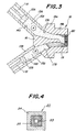
- FIG. 5(a) is a front view for outlining a sintered laminated body 32 for the electrochemical cell according to the present invention.
- Fig. 5 (b) is a front view of illustrating the cell 31A.
- the sintered laminated body 32 comprises an anode layer 27 and a separator 28.
- the anode layer 27 is formed with a given number of through-holes 29A, whereas a given number of through-holes 30A are similarly formed in the separator 28.
- a reference numeral 74 denotes a boundary between the anode layer and the separator.
- a film 56 of a solid electrolyte is formed to cover at least a surfaced 27a of the porous anode layer 27 of the sintered laminated body 32, and a cathode film 33 is formed on the solid electrolyte film 56.
- a terminal end portion of the solid electrolyte film 56 contacts an upper end portion of the separator 28 so that one gas (for example, oxidizing gas) through the through-holes 29A, 30A will not directly contact with the other gas (for example, a fuel gas) passing along the outside of the cell 1A.
- An extruding machine as shown in Fig. 3 may be used to produce a molded body for the sintered laminated body in Fig. (a).
- Fig. 6 is a front view for outlining an electrochemical cell 31B according to another embodiment of the present invention.
- the sintered laminated body 60 comprises an anode layer 34 and a separator 35.
- the anode layer 34 are formed with a given number of through-holes 29B in such a manner that the through-holes 29B are arranged in a matrix of 4 x 2 as viewed in a cross sectional face.
- Through holes 30B are also formed in the separator 35 in such a manner that the through-holes 30B are arranged in a matrix of 4 ⁇ 2.
- Figs. 7 and 8 are front views for outlining electrochemical cells 58 and 62 according to further embodiments of the present invention, respectively.
- a sintered laminated body 71 comprises an anode layer 59 and a separator 70.
- a given number of through-holes 29D are formed in the anode layer 59, whereas through-holes 30D are also formed in the separator 70.
- three through-holes 61 are formed along a boundary 74 between the anode layer 59 and the separator 70 such that each of the through-holes 61 exists bridging both the anode layer 59 and the separator 70.
- through-holes may be provided along the boundary between the separator and the anode layer.
- the power-generating efficiency, etc. of the anode layer can be improved by flowing an oxidizing gas such as air through these through-holes.
- a film 56 of a solid electrolyte is formed to cover at least a surface 59a of the porous anode layer 59, and a cathode film 33 is formed on the solid electrolyte film 56.
- the sintered laminated structure 72 comprises an anode 62 and a separator 63.
- a given number of through-holes 29E are formed in the anode layer 62, whereas the separator 63 is also formed with through-holes 30E.
- a solid electrolyte film 56 is formed to cover at least a solid electrolyte film 56 to cover at least a surface 62a of the porous anode layer 62 of the sintered laminated structure 72, and a cathode film 33 is formed on the solid electrolyte film 56.
- the anode layer 62 is thicker than the separator 63, and a number of through-holes 29E are formed in the anode layer 62.
- the resistance of the separator is generally greater than that of the anode. For this reason, the entire resistance of the sintered laminated structure 72 is minimized by making the anode layer greater than the separator and thinning the separator having a large resistance.
- Fig. 9(a) is a front view for outlining a sintered laminated structure 36 as a still further embodiment.
- Fig. 9 (b) is a front view for illustrating an electrochemical cell 31C.
- Fig. 9(c) is a sectional view of the cell 31C cut along a longitudinal direction thereof.
- the sintered laminated structure 36 comprises an anode layer 37 and a separator 38.
- a given number of through-holes 29C are formed in the anode layer 37, whereas the separator is also formed with through-holes 30C.
- a solid electrolyte film 56 is formed to cover side faces 37a of the anode layer 37 and upper portions of side faces 38a of the sintered laminated structure 38.
- a cathode film 33 is formed on the solid electrolyte film 56. Thereby, the cell 31C is formed.
- a terminal end of the through-hole 30C of in the separator is communicated with that of the through-hole 29C in the anode layer 37, and the length of the anode layer 37 is smaller than that of the separator 38.
- the solid electrolyte film 56 covers an entire side face of the anode layer 37 on a terminal end side as viewed in a longitudinal direction as well as upper end portion of a side face 38b of the separator 38 at a terminal end side as viewed in the longitudinal direction.
- an oxidizing gas is fed into the through-holes 30C of the separator 38 as shown by an arrow E on generating electric power.
- the oxidizing gas hits upon a terminal wall face of the separator and changes its flowing direction so that the oxidizing gas may enter the through-hole 29C in the air electrode layer 37 and discharged as shown by an arrow F.
- a unit cell for a solid oxide fuel cell as shown in Fig. 5(b) and a unit cell as a comparative example were produced, and each cell was subjected to a power generating test.
- a body was formulated by charging a kneader with 100 parts by weight of a powdery raw material for lanthanum manganite having the average particle diameter of 4 ⁇ m, 10 parts by weight of cellulose, 3 parts by weight of methyl cellulose and 18 parts by weight of water.
- a green body of an air electrode layer having a diameter of 50 mm and a length of 300 mm was produced in a vacuum pug mill by using the above body.
- a body for a separator was formulated by charging a kneader with 100 parts by weight of a powdery raw material for lanthanum chromite having the average particle diameter of 3 ⁇ m, 3 parts by weight of methyl cellulose and 12 parts by weight of water.
- a green body for the separator having a diameter of 50 mm and a length of 300 mm was produced in the vacuum pug mill by using the above body.
- a molded body having a configuration as shown in Fig. 5 (a) was produced by using an extruding machined as shown in Fig. 3. While the speed of each plunger was adjusted, each piston was simultaneously advanced to extruding the body. The thus molded body was placed and dried in a thermostat and humidistat container. Then, the molded body was placed in an electric furance where it was heated up to 1550°C at a heating rate of 200°C/hour and held at 1550°C for 4 hours. Then, the fired body was left to be cooled down to room temperature. The fired body had a dimension of 24 mm ⁇ 8 mm ⁇ 300 mm with through holes each having a rectangular dimension of 3 mm ⁇ 4 mm.
- the fired body comprised of an air electrode layer and a separator.
- a sample of 10 mm ⁇ 10 mm ⁇ 1 mm was cut from the fired body and the porosity was measured.
- the porosity of the air electrode layer was 35%, whereas that of the separator was 0.3%.
- a sintered laminated structure as a comparative example was produced in the same manner as in the above example, provided that no through-hole was formed in the separator.
- a sample having a dimension of 24 mm ⁇ 8 mm ⁇ 50 mm was cut out from each of the above fired bodies as an example of the present invention and the comparative example, and a film of 8 mol yttria-stabilized zirconia (solid electrolyte) was formed in a thickness of 100 ⁇ m on the lanthanummanganite by using a plasma spraying machine.
- Nickel-zirconia cermet was formed on the stabilized zirconia film by screen printing. The thus obtained assembly was placed in the electric furnace where it was thermally treated at 1400°C. Thereby, unit cells as the example of the present invention and comparative example were obtained.
- An electric power-generating test was effected by using an electric power testing apparatus schematically shown in Figs. 10 and 11.
- Each cell 40 as an example or a comparative example was set between electricity collectors 41, 47, and platinum wires 42, 43 were connected to respective electricity collectors 41, 47.
- the assembly was placed in a container 45. Hydrogen was wetted by passing it through a bubbler, fed into the container as shown by an arrow G, contacted with the a fuel electrode, and discharged outside from the container as shown by an arrow H.
- the unit cell 40 was fixed gas-tightly between manifolds 44, so that air is fed through one of the manifolds 44 as shown by an arrow I, and flown through through-holes 29A and 30A, and discharged outside as shown by an arrow J.
- air fed into the through-holes 30A of a separator was passed outside while capturing heat generated on generation of electric power and cooling the unit cell. Thereby, the temperature distribution of the unit cell in a longitudinal direction was made uniform.
- lanthanum chromite used for the separator has higher resistance in a reducing atmosphere such as hydrogen than in air.
- the resistance of the separator could be reduced by providing the through-holes in the separator and feeding air into the through-holes, so that the resistance of the cell itself could be reduced.
- the unit cell as a comparative example was tested in the same manner as mentioned above.
- Each of the unit cells as the example of the present invention and the comparative example was used for measuring the maximum output of the unit cell under a electric power generation condition at a temperature of 1000°C.
- An output density per unit weight is shown in Table 2. From these results, it is seen that if the volumes of the unit cells are equal, the example of the present invention in which the through-holes were provided in the separator had higher output density per unit weight as compared with the comparative example.
- Unit cell as shown in Figs. 9(a) to 9(c) was produced, and subjected to the electric power-generating test.
- This unit cell 31 was produced in the same manner as for the unit cell 31A shown in Fig. 5(b).
- the unit cell 31C was set in an electric power-generating apparatus, and subjected to the electric power-generating test.
- Fig. 12 is a schematic view for outlining this electric power-generating apparatus.
- a positive electricity collector plate 66 Inside a container 64 were set a positive electricity collector plate 66, two unit cells 31C and a negative electricity collector plate 67. Nickel felt pieces 68 were filled between the positive electricity collector plate 66 and the unit cell 31C, between the adjacent unit cells 31 and between the unit cell 31C and the negative electricity collector plate 67, thereby realizing electric connection.
- a fuel gas feed opening 64a was provided at one end portion of the container, whereas a combustion gas discharge opening 64b was provided at an opposite end portion thereof.
- Oxidizing gas feed pipes 65 were fitted to a side of the discharge opening 64b such that tips of the feed pipes 65 were gas-tightly attached to ends of the unit cells 31C, respectively.
- Hydrogen was wetted by passing it through a bubbler at room temperature, fed into the container 64 as shown by arrows K, and passed between the adjacent unit cells 31C and between the unit cells 31 and the electricity collector plates 66 and 67 as shown by arrows L.
- air was flown into the feed pipes 65 as shown by arrows N, flown into through holes 30C of a separator 38 and then through holes 29C of an air electrode layer 37, and discharged outside from the unit cells as shown by arrows F. Used air and hydrogen were reacted within a combustion space 77, and combustion waste gas was discharged through the discharge opening 64b as shown by an arrow M.
- the above electricity-generating test revealed that 0.17 W/(cm 2 ⁇ g) was obtained as an output density per unit weight. Further, while air passed the separators, air cooled the unit cell, and air was preheated. As a result, the temperature distribution of the entire unit cell was made uniform.
- a steam electrolysis cell as an example having a configuration as shown in Fig. 5(b) and another steam electrolysis cell as a comparative example were produced, and their hydrogen-producing rates per unit weight of the cell were measured.
- a laminated body composed of an anode and a separator was prepared in the same manner as in Experimental 2.
- the laminated body was dried and fired as in the same manner as in Experiment 2.
- a sample having a dimension of 10 mm ⁇ 10 mm ⁇ 1 mm were cut out from the anode layer and the separator of the fired body, and their porosity was measured. As a result, the porosity of the anode layer was 35%, whereas that of the separator was 0.3%.
- a sintered laminated structure as a comparative example was produced in the same manner as above, provided that no through-hole was formed in the separator.
- a sample having a dimension of 24 mm ⁇ 8 mm ⁇ 50 mm was cut out from each of the fired bodies as the example of the present invention and the comparative example, and a film of 8 mol yttria-stabilized zirconia (solid electrolyte) was formed in a thickness of 100 ⁇ m on the lanthanum manganite by using a plasma spraying machine. A platinum paste was printed on this film.
- the thus obtained assembly was set in the electric furnace where the assembly was thermally heated at 1400°C. By so doing, the steam electrolysis cells as the example of the present invention and comparative example were obtained.
- the area of the cathode was 8 cm 2 in each cell.
- Each of the steam electrolysis cells as the example and the comparative example was set in the test apparatus schematically shown in Figs. 10 and 11, and subjected to an electrolysis test.
- Helium gas containing 10% of steam was fed to a side of the cathode at a rate of 500 cc/min, whereas air was fed to a side of the anode at a rate of 200 cc/min.
- the functions possessed by respective ceramics in the sintered laminated functional ceramic structure such as the ceramic filter or the electrochemical cell can be enhanced, and the weight of the sintered laminated structure can be reduced, and structural strength of the sintered laminated structure can be enhanced.
- each of thorugh-holes provided in the ceramic honeycomb structure is not limited to any specific one, which may be triangular, rectangular, hexagonal or of other polygonal forms.
- the sectional shapes of the through-holes may be any of the above shapes or a combination thereof.
- the sectional shape of the through-hole is equilateral triangular, regular square, rectangular or regular hexagonal.
- the thickness of the wall of the honeycomb structure to contact the solid electrolyte is not more than 0.5 mm. By so doing, polarization resistance at a portion of the ceramic honeycomb structure contacting the solid electrolyte is conspicuously decreased. From this point of view, the thickness of the above wall is preferably not more than 0.3 mm. In order to support the solid electrolyte, it is preferably that the thickness of the above wall is further preferably not less than 0.1 mm.
- the thickness of those walls of the ceramic honeycomb structure as not contacting the solid electrolyte is not specifically limited. However, from the standpoint of view of lightening the substrate by as much as possible, the thickness of those walls is preferably not more than 1 mm, whereas the thickness is preferably not less than 0.1 mm from the standpoint of increasing the strength.
- both vertical and lateral widths of the sectional face of each of the through-holes are preferably not more than 5 mm, and they are preferably not less than 0.5 mm from the standpoint of easy production.
- Fig. 13 is a front view for illustrating an electrochemical cell 101 as an embodiment according to the second aspect of the present invention.
- a substrate 102 which functions as an electrode is constituted by a ceramic honeycomb structure.
- the cross sectional shape of the outer peripheral wall 102a of the ceramic honeycomb structure 102 is circular, but it is not specifically limited to a circular form.
- Inside the wall 102a are provided a number of linear walls extending, for example, vertically or laterally extending in a grid pattern.
- the honeycomb structure includes walls 102c extending in the vertical direction and those 102b extending in the lateral direction. The walls 102b cross those 102c at right angles, and through-holes having a regular square form are formed among these walls.
- a solid electrolyte film 104 is formed on the outer surface of the outer peripheral wall 102a of the ceramic honeycomb structure 102, and a cathode film 105 is formed on the solid electrolyte film 104, provided that no solid electrolyte is not formed on a part of the outer surface of the wall, and instead an interconnector 106 is formed there. End portions of the gas-tight solid electrolyte film 104 continue to those of the interconnector 106 so that a gas flowing inside the through-holes 103 may leak outside the cells 101.
- the gas may be flown simultaneously through the through-holes 103A and 103B.
- the electrode constituting the ceramic honeycomb structure may be an anode or a cathode, but the anode is preferable.
- a main starting material of the anode is preferably a perovskite type complex oxide containing lanthanum, more preferably lanthanum manganite or lanthanum cobaltite, and most preferably lanthanum manganite.
- Lanthanum manganite may be doped with strontium, calcium, chromium, cobalt, iron, nickel, aluminum or the like.
- a main starting material of the cathode is preferably nickel, nickel oxide, a mixed powder such as nickel-zirconia mixed powder, nickel oxide-zirconia mixed powder, palladium-zirconia mixed powder, platinum-zirconia mixed powder, nickel-ceria, nickel oxide-ceria, palladium-ceria, platinum-ceria, palladium, platinum or the like.
- the material for the solid electrolyte film As the material for the solid electrolyte film, yttria-stabilized zirconia or yttria partially stabilized zirconia is preferred, but other material may be used. Further, in the case of the NOx decomposing cell, the solid electrolyte film is particularly preferably made of cerium oxide-based ceramic.
- a perovskite type complex oxide containing lanthanum is preferred, and lanthanum chromite is more preferable, because these materials have heat resistance, oxidation resistance, and reduction resistance.
- Lanthanum chromite may be doped with any of the above mentioned metals.
- the ceramic honeycomb structure to be used as an electrode substrate is produced by extruding a body as a raw material for the above electrode through a die for a molded body of a target honeycomb structure.
- the body for constituting the molded body of the electrode may be produced by mixing an organic binder, a pore-forming material and water together.
- organic binder polymethyl acrylate, nitrocellulose, polyvinyl alcohol, methyl cellulose, ethyl cellulose, starch, wax, acrylic acid polymer, methacrylic acid polymer, etc. may be recited.
- pore-forming material cellulose, carbon, acryl powder, etc. may be recited.
- an addition amount of the organic binder is preferably 0.5 to 5 parts by weight, and more preferably 2 to 20 parts by weight.
- the ceramic honeycomb structure is constituted by one of the electrodes and the interconnector
- a molded body is produced by simultaneously feeding the body corresponding to a ceramic layer to constitute one of the electrodes and that corresponding to another ceramic layer to constitute the interconnector through the die, and the ceramic honeycomb structure is produced by firing the resulting molded body.
- the body to constitute the green molded body for the interconnector may be produced by mixing an organic binder and water into the above main raw material.
- organic binder polymethyl acrylate, nitrocellulose, polyvinyl alcohol, methyl cellulose, ethyl cellulose, starch, wax, acrylic acid polymer, methacrylic acid polymer, etc. may be recited.
- an addition amount of the organic binder is preferably 0.5 to 5 parts by weight.
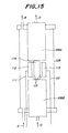
- Fig. 14 is a sectional view for illustrating an electrochemical cell 118 as another embodiment according to the second aspect of the present invention.
- a substrate 119 of the cell 118 is constituted by a ceramic honeycomb structure having an almost rectangular sectional shape.
- the upper portion of the substrate 119 constitutes an anode 122, and an interconnector 125 is joined to an under side of the anode 122 by integral firing.
- a wall 122a horizontally extends to cover the anode 122, and walls 122e extend vertically from respective terminal ends of the wall 122a, so that the anode 122 is externally defined by the walls 122a and 122e inclusive.
- the thickness of each of the walls 122a and 122e is not more than 0. 5 mm.
- Walls 122b and 122f are laterally and vertically formed in a grid pattern inside the walls 122a and 122e defining the outer periphery of the anode 122.
- a number of through-holes 123C are formed by the walls 122b and 122f.
- a line of through-holes 123A are formed between the walls 122a and the adjacent walls 122 b.
- a row of through-holes 123B are formed between each of the walls 122e and the adjacent wall 122f.
- the through-holes 123A and 123B directly face the walls 122a and 122e defining the outer periphery of the anode 122.
- the anode 122 itself constitutes a part of the honeycomb structure.
- Walls 125b of the interconnector 125 vertically extend and are joined to lowermost portions of the walls 122f of the anode 122, respectively, while the walls 125b continue to a wall 125a defining an outer end of the interconnector 125.
- a reference numeral 129 denotes a joint between the anode and the interconnector.
- Through-holes 124 are formed by the walls 122b, 122f, 122b and 125a, and face the anode and the interconnector.
- a horizontal portion 120a of a solid electrolyte film 120 is formed on the surface 122c of the wall 122a of the anode 122, and a vertical portion 120b of the solid electrolyte film 120 is formed on a surface 122d of each of the walls 122e.
- An under end of each vertical portion 120b of the solid electrolyte film 120 extends down to the surface 125c of the interconnector 125.
- the solid electrolyte film 120a, 120b keeps the through-holes 123A, 123B and 123C, 124 inside the ceramic honeycomb structure 119 gas-tight.
- a horizontal portion 121a of a cathode film 121 is formed on that 120a of the solid electrolyte film 120, and a vertical portion 121b of the cathode film 121 is formed on each of the vertical portions 120b of the solid electrolyte film 120.
- Electromotive forces are simultaneously generated in the entire solid electrolyte film 120a, 120b by flowing an oxidizing gas through at least the through-holes 123A, 123B on generating electric power.
- the oxidizing gas may be also flown through the through-holes 123C and 124.
- the oxidizing gas flowing the through-holes 123C and 124 goes outside the unit cell, while capturing the heat produced on power generation, so that the unit cell is cooled. Thereby, the temperature distribution of the unit cell as viewed in a longitudinal direction can be made uniform.
- lanthanum chromite which is generally used as a material for the interconnector has a lower resistance in an oxidizing atmosphere than in a reducing atmosphere.
- the oxidizing gas may be fed through the through-holes 124, too.
- the ceramic honeycomb substrate having the structure in which the electrode and the interconnector are integrated as shown in Fig. 14 is particularly preferably used.
- the substrate of such a structure has a crossbeam structure, and therefore its structural strength is high.
- the sectional shape of the electrochemical cell is preferably rectangular as shown in Fig. 14.
- a fuel gas flows outside the unit cell.
- the sectional shape of the unit cell is circular as shown in Fig. 13
- the fuel gas also flows in an unnecessary portion not participating in the reaction.
- the sectional shape of the electrochemical cell is rectangular, such a dead space is small, so that the fuel-utilizing efficiency is improved.
- a body was formulated by charging 100 parts by weight of a raw material powder for lanthanum manganite having the average particle diameter of 3 ⁇ m, 5 parts by weight of cellulose, 3 parts by weight of methyl cellulose and 12 parts by weight of water into a kneader, and kneading the mixture.
- This body was molded into a molded body having a tubular shape of 50 mm in diameter and 300 mm in length by using the vacuum pug mill.
- To a cylinder of an extruder was attached a die for the formation of a honeycomb structure. The molded body was placed in the cylinder, and a piston was advanced in the cylinder to extrude the body.
- a ceramic honeycomb structure having a structure as shown in Fig.
- This molded body had an outer shape of 18 mm in diameter and 500 mm in length, and through-holes each had an almost square cross sectional shape with walls being 0.6 mm in thickness over the entirety of the molded body.
- the vertical and lateral widths of each through-hole were 0.6 mm, and the pitch of the through-holes was 1.2 mm.
- the molded body was dried at 100°C by using a dryer, then heated up to 1600°C at a heating rate of 100°C in an electric furnace, and fired at 1600°C for 3 hours, thereby obtaining a ceramic honeycomb structure 101.
- This structure had an outer shape of 15 mm in diameter and 300 mm in length, and through-holes each had an almost square cross sectional shape with walls being 0.6 mm in thickness over the entirety of the fired body.
- the vertical and lateral widths of each through-hole were 0.5 mm, and the pitch of the through-holes was 1.0 mm.
- a portion of the outer peripheral surface of the resulting ceramic honeycomb structure 101 to be formed with no interconnector film was masked with a heat-resistive tape, and a film of an interconnector was formed on the remainder of the outer peripheral surface by using a plasma sprayer.
- lanthanum chromite powder having the average particle diameter of 35 ⁇ m was melted in a plasma gas of argon and hydrogen, and the interconnector film was formed in a thickness of 150 ⁇ m on the honeycomb structure under an output of 40 kw. Then, the mask was peeled off.
- a film of a solid electrolyte was formed by using the plasma sprayer.
- a portion of the resulting ceramic honeycomb structure to be formed with no solid electrolyte film was masked with a heat-resistive tape.
- a 9 mol% yttria stabilized zirconia powder having the average particle diameter of 25 ⁇ m was melted in the plasma gas of argon and hydrogen, and the solid electrolyte film was formed in a thickness of 100 ⁇ m on the honeycomb structure under an output of 40 kw.
- the mask was peeled off.
- the entire structure was heated at 1450°C for 3 hours in air inside the electric furnace.
- a fuel electrode was formed on the solid electrolyte by screen printing.
- a paste was formulated by mixing NiO powder, yttria stabilized zirconia powder and polyethylene glycol at such a ratio as to give a volumeric percentage of nickel being 60 vol. %.
- a film of this paste was formed on the solid electrolyte film by a screen printer for tubular bodies. The thickness of the paste film was 100 ⁇ m.
- the entire structure was placed in the electric furnace where the fuel electrode film was formed of a nickel-zirconia cermet by firing the structure at 1400°C for 2 hours. Thereby, a unit cell in Example 2-1 was produced.
- Example 2-2 In order to examining an effect of the thickness of walls of the ceramic honeycomb structure, unit cells in Examples 2-2 and 2-3 were produced in the same manner as in above Example 2-1.
- the thickness of the walls of the fired structure was 0.1 mm, and that of the walls of the fired structure in Example 2-3 was 0.2 mm.
- a unit cell was produced in the same manner as in Example 2-1, provided that a tubular substrate was produced as an air electrode substrate.
- a die cap for the formation of a tubular body was attached to an extruder, and a molded body was then placed in the extruding apparatus. The piston was advanced to obtain a tubular molded body having a configuration of 18 mm in diameter, 2.4 mm in thickness and 500 mm in length.
- a tubular air electrode substrate pipe was produced by firing the molded body in the same manner as in Example 2-1. The fired body had a configuration of 15 mm in diameter, 2.0 mm in thickness and 300 mm in length.
- An electric power generating test was effected by using an electric power testing apparatus schematically shown in Figs. 15 and 16.
- Each of the unit cells 140 in Examples and Comparative Examples was placed between electricity collectors 112 and 113, and platinum wires 110, 111 were connected to respective electricity collectors.
- As the electricity collectors 112, 113 nickel plates were used. Nickel felts 115 were interposed between each of the electricity collectors 112, 113 and the unit cells 114.
- the resulting assembly was placed in a container 109. Hydrogen was wetted by passing it through a bubbler at room temperature, fed into the vessel as shown by an arrow A, contacted with the fuel electrode of the unit cell 114 and discharged outside the container 109 as shown by an arrow B.
- the unit cell 114 was gas-tightly fixed to ceramic manifolds 8A and 8B. Air was fed through the manifold 8B as shown by an arrow C, contacted with the fuel electrode of the unit electrode 114, flown in the unit cell, and discharged outside the container as shown by an arrow D.
- the unit cell according to the second aspect of the present invention has an extremely smaller polarized value as compared with those in Comparative Examples. Further, the polarized value was extremely reduced by reducing the thickness of the walls to not more than 0.5 mm.
- a body was formulated by charging 100 parts by weight of a raw material powder for lanthanum manganite having the average particle diameter of 3 ⁇ m, 5 parts by weight of cellulose, 3 parts by weight of methyl cellulose and 14 parts by weight of water into a kneader, and kneading the mixture.
- This body was molded into a molded body having a tubular shape of 50 mm in diameter and 300 mm in length.
- another body was formulated by charging 100 parts by weight of a raw material powder for lanthanum chromite having the average particle diameter of 3 ⁇ m, 3 parts by weight of methyl cellulose and 14 parts by weight of water into the kneader, and kneading the mixture.
- This body was molded into a molded body having a tubular shape of 50 mm in diameter and 300 mm in length.
- a molded body for a substrate 119 was formed by using and simultaneously extruding the above molded bodies. At that time, an extruding machine as designed in Fig. 17 was used. That is, the body 139A for an air electrode and the body 139B for an interconnector were fed into passages 140A and 140B of respective molding barrels 136A and 136B. A shaft 138A of a plunger 137A was moved to push the air electrode body 139A toward a die 132, whereas a shaft 138B for a plunger 137B was simultaneously moved to push the body 139B toward the die 132.
- the die 132 comprises an inlet portion 132a and an outlet portion 132b.
- the inlet portion 132a is provided with two inlet passages 134A and 134B, and a partition is provided between the inlet passages 134A and 134B.
- the cross sectional shape of each inlet passage is circular.
- the cross sectional shape of the outlet passage 135 in the outlet portion 132b is rectangular.
- a die cap 133 is arranged at a tip of the die 132.
- the extruding speed and the pressure of each of the first and second plungers 137A and 137B were so adjusted that the molded body might not be bent.
- the thus obtained molded body had a sectional shape corresponding to the configuration of the substrate 119 in Fig. 14.
- This molded body was dried at 100°C by using the dryer, then heated up to 1600°C at a heating rate of 100°C/hour in the electric furnace, and fired at 1600°C for 3 hours, thereby obtaining the substrate 119.
- This substrate 119 had a dimension of about 6 mm in vertical width, about 20 mm in lateral width and about 300 mm in length.
- a portion of the structure to be formed with no fuel electrode film was masked with a heat-resistive tape, and a fuel electrode film was formed by plasma spraying a mixed powder composed of 50 wt% of nickel oxide and 50 wt% of 8 mol% yttria stabilized zirconia upon the solid electrolyte film at an output of 40 kw.
- the thickness of the walls of the honeycomb structure contacting the solid electrolyte film was varied by changing the configuration of the die cap as shown in Table 4.
- a unit cell in Comparative Example 2-2 was produced in the same manner as in Example 2-4.
- the unit cell 126 having a structure shown in Fig. 18 was produced by changing the shape of the die cap. With respect to the same constituent elements as shown in Fig. 15, same reference numerals are given to them, and explanation thereof is omitted.
- the cross sectional shape of a substrate 145 of the unit cell 126 is almost rectangular, and an upper portion of the substrate 145 is constituted by an air electrode 127, and an interconnector 130 is joined to the under side of the air electrode 127 by integral firing.
- a plurality of through-holes 128 are formed bridging the air electrode 127 and the interconnector 130. Each through-hole 128 faces both the air electrode 127 and the interconnector 130.
- the substrate when the substrate was made as the honeycomb structure according to the second aspect of the present invention, the output density per unit weight of the unit cell remarkably increased. This is because the polarized value is small as the walls of the air electrode can be thinned. Further, since the substrate was made in a form of the honeycomb structure, the substrate has sufficient strength as the structure for the solid oxide fuel cell.
- a high temperature steam electrolysis cell according to an embodiment of the second aspect of the present invention having the configuration of Fig. 14 was produced in the same manner as in Examples 2-4, 2-5 and 2-6, provided that the thickness of walls contacting a solid electrolyte film was 0.3 mm. Further, a high temperature steam electrolyte cell according to a comparative example having the structure shown in Fig. 18 was produced as in Comparative Example 2-2.
- the invention example has a higher electric current density and a higher electrolysis efficiency. This is considered that since the thickness of the anode facing the solid electrolyte can be thinned, oxygen generated in the anode can be smoothly removed.
Landscapes
- Chemical & Material Sciences (AREA)
- Engineering & Computer Science (AREA)
- Chemical Kinetics & Catalysis (AREA)
- Electrochemistry (AREA)
- Life Sciences & Earth Sciences (AREA)
- General Chemical & Material Sciences (AREA)
- Sustainable Energy (AREA)
- Sustainable Development (AREA)
- Manufacturing & Machinery (AREA)
- Materials Engineering (AREA)
- Inorganic Chemistry (AREA)
- Ceramic Engineering (AREA)
- Metallurgy (AREA)
- Organic Chemistry (AREA)
- Geology (AREA)
- Fuel Cell (AREA)
- Laminated Bodies (AREA)
- Filtering Materials (AREA)
Abstract
Description
(Firing step) Next, the molded body was placed and dried in a thermostat and humidistat container. Then, the molded body was set in an electric furnace where it was heated up to 1500°C at a heating rate of 200°C/hour and held at 1500°C for 3 hours. Thereafter, the fired body was left to be cooled down to room temperature, thereby obtaining a sintered laminated body 1 having a tubular shape as shown in Fig. 1. In an
| Kind of filter | Treating time period (min.) | Treated amount (cc) |
| Example, Fig. 1 | 1 | 200 |
| Example, Fig. 1 | 3 | 600 |
| Example, Fig. 1 | 10 | 1900 |
| Comparative Example, Fig. 4 | 1 | 180 |
| Comparative Example, Fig. 4 | 3 | 400 |
| Comparative Example, Fig. 4 | 10 | 900 |
| Output density per unit weight | |
| Example | 0.18 W/(cm2 · g) |
| Comparative Example | 0.11 W/(cm2 · g) |
| Shape of air electrode substrate | Thickness of wall of honeycomb structure or thickness of tubular substrate | Polarized value η at 0.3A/cm2 (mV) | |
| Example 2-1 | Fig. 1 | 0.5 | 70 |
| Example 2-2 | Fig. 1 | 0.1 mm | 30 |
| Example 2-3 | Fig. 1 | 0.2 | 35 |
| Comparative Example 2-1 | | 2 | 250 |
| Shape of substrate | Thickness of walls of air electrode contacting solid electrolyte | Output density per unit weight (W/g) | |
| Example 2-4 | Fig. 2 | 0.5 mm | 0.55 |
| Example 2-5 | Fig. 2 | 0.3 mm | 0.81 |
| Example 2-6 | Fig. 2 | 0.1 mm | 0.82 |
| Comparative Example 2-2 | Fig. 6 | 2 mm | 0.27 |
Claims (11)
- A sintered laminated structure comprising a plurality of ceramic layers being made of ceramic materials different from one another, wherein each of the ceramic layers is provided with through-holes passing said each of the ceramic layers.
- The sintered laminated structure set forth in claim 1, which is a sintered laminated structure for use in an electrochemical cell and wherein the sintered laminated structure has a planar shape, and comprising an electrode layer and a separator layer.
- The sintered laminated structure set forth in claim 1, which is a ceramic filter to be used in a filtering device.
- An electrochemical cell comprising a sintered laminated structure comprising a plurality of ceramic layers having ceramic materials different from one another, wherein each of the ceramic layers is provided with through-holes passing said each of the ceramic layer, and said sintered laminated structure comprises an electrode layer and a separator, said electrochemical cell further comprising a solid electrolyte film formed on the electrode layer to cover an entirety of the electrode layer, and an opposite electrode layer formed on said solid electrolyte film.
- A process for producing a sintered laminated structure, comprising the steps of: forming a molded body of said sintered laminated structure by simultaneously feeding ceramic bodies to a die having holes to form at least one through-hole in each of the said ceramic bodies being adapted for respective ceramic layers to be laminated and being made of respective materials different from one another, and firing said molded body.
- A self-supporting type substrate for an electrochemical cell, said substrate comprising at least one of electrodes of the electrochemical cell and having a honeycomb ceramic structure, said honeycomb ceramic structure comprising a wall portion on which a film of a solid electrolyte is to be formed, and said wall portion having a thickness of 0.5 mm or less.
- The self-supporting type substrate for the electrochemical cell set forth in claim 6, wherein said honeycomb ceramic structure comprises said at least one of the electrodes and an interconnector.
- The self-supporting type substrate for the electrochemical cell set forth in claim 6 or 7, wherein said one of the electrodes is an anode.
- A process for producing a self-supporting type substrate for an electrochemical cell, said process comprising the steps of preparing a first body for forming a ceramic layer to constitute one of electrodes of the electrochemical cell and a second body for forming a ceramic layer to constitute an interconnector, forming a molded body by simultaneously feeding said first and second bodies into a die to form a honeycomb ceramic structure, and firing the molded body, wherein said substrate comprising at least one of electrodes of the electrochemical cell and having the honeycomb ceramic structure, said honeycomb ceramic structure comprises said at least one of the electrodes and an interconnector as well as a wall portion on which a film of a solid electrolyte is to be formed, and said wall portion having a thickness of 0.5 mm or less.
- An electrochemical cell comprising the substrate for the electrochemical cell set forth in claim 6 or 7, and a solid electrolyte film formed on the substrate, and the other electrode formed on said solid electrolyte film.
- An electrochemical cell comprising the substrate for the electrochemical cell set forth in claim 8, and a solid electrolyte film formed on the substrate, and the other electrode formed on said solid electrolyte film.
Priority Applications (1)
| Application Number | Priority Date | Filing Date | Title |
|---|---|---|---|
| EP04011257A EP1465278B1 (en) | 1996-09-26 | 1997-09-26 | Elctrochemical cell comprising an electrode with honeycomb structure |
Applications Claiming Priority (9)
| Application Number | Priority Date | Filing Date | Title |
|---|---|---|---|
| JP254412/96 | 1996-09-26 | ||
| JP25441296 | 1996-09-26 | ||
| JP25441296 | 1996-09-26 | ||
| JP124597 | 1997-01-08 | ||
| JP1245/97 | 1997-01-08 | ||
| JP00124597A JP3668349B2 (en) | 1997-01-08 | 1997-01-08 | Electrochemical cell substrate, electrochemical cell, and method for producing electrochemical cell substrate |
| JP09118061A JP3126939B2 (en) | 1996-09-26 | 1997-05-08 | Manufacturing method of laminated sintered body |
| JP11806197 | 1997-08-05 | ||
| JP118061/97 | 1997-08-05 |
Related Child Applications (1)
| Application Number | Title | Priority Date | Filing Date |
|---|---|---|---|
| EP04011257A Division EP1465278B1 (en) | 1996-09-26 | 1997-09-26 | Elctrochemical cell comprising an electrode with honeycomb structure |
Publications (3)
| Publication Number | Publication Date |
|---|---|
| EP0834949A2 true EP0834949A2 (en) | 1998-04-08 |
| EP0834949A3 EP0834949A3 (en) | 2000-09-06 |
| EP0834949B1 EP0834949B1 (en) | 2006-08-09 |
Family
ID=27274837
Family Applications (2)
| Application Number | Title | Priority Date | Filing Date |
|---|---|---|---|
| EP04011257A Expired - Lifetime EP1465278B1 (en) | 1996-09-26 | 1997-09-26 | Elctrochemical cell comprising an electrode with honeycomb structure |
| EP97307578A Expired - Lifetime EP0834949B1 (en) | 1996-09-26 | 1997-09-26 | Laminated structures of sintered ceramic material, electrochemical cells, filters and process for producing such sintered laminated structures |
Family Applications Before (1)
| Application Number | Title | Priority Date | Filing Date |
|---|---|---|---|
| EP04011257A Expired - Lifetime EP1465278B1 (en) | 1996-09-26 | 1997-09-26 | Elctrochemical cell comprising an electrode with honeycomb structure |
Country Status (3)
| Country | Link |
|---|---|
| US (2) | US5964991A (en) |
| EP (2) | EP1465278B1 (en) |
| DE (1) | DE69736454T2 (en) |
Cited By (8)
| Publication number | Priority date | Publication date | Assignee | Title |
|---|---|---|---|---|
| WO1999054131A1 (en) * | 1998-04-16 | 1999-10-28 | Alstom Uk Ltd. | Glass-ceramic coatings and sealing arrangements and their use in fuel-cells |
| WO2002019445A3 (en) * | 2000-09-01 | 2003-01-16 | Global Thermoelectric Inc | Electrode pattern for solid oxide fuel cells |
| WO2003012907A2 (en) * | 2001-07-27 | 2003-02-13 | Siemens Aktiengesellschaft | High-temperature fuel cell reactor comprising high efficiency cells |
| WO2003031023A1 (en) * | 2001-10-09 | 2003-04-17 | Ngk Insulators,Ltd. | Honeycomb filter |
| EP1433767A1 (en) * | 2001-09-26 | 2004-06-30 | Ngk Insulators, Ltd. | Laminated ceramic sintered compact, method for producing laminated ceramic sintered compact, electrochemical cell, electroconductive joining member for electrochemical cell, and electrochemical device |
| DE102004008231B4 (en) * | 2003-03-18 | 2009-05-07 | Ford Motor Co., Dearborn | Fuel cell assembly and method of making a flat tube fuel cell |
| CN102211923A (en) * | 2010-03-30 | 2011-10-12 | 日本碍子株式会社 | Ceramic clay, ceramic formed article, and ceramic structure, and manufacturing methods thereof |
| DE10301959B4 (en) | 2002-01-21 | 2022-06-09 | Ngk Insulators, Ltd. | Honeycomb porous body, its use and method of manufacture |
Families Citing this family (41)
| Publication number | Priority date | Publication date | Assignee | Title |
|---|---|---|---|---|
| US6622872B1 (en) * | 1997-11-07 | 2003-09-23 | California Institute Of Technology | Micromachined membrane particle filter using parylene reinforcement |
| JP2000053424A (en) * | 1998-07-24 | 2000-02-22 | Sulzer Hexis Ag | Perovskite for coating of interconnector, interconnector and fuel cell |
| DE29822871U1 (en) * | 1998-12-23 | 1999-02-25 | Thomas Josef Heimbach GmbH & Co., 52353 Düren | Filter device |
| JP2001224963A (en) * | 2000-02-16 | 2001-08-21 | Nissan Motor Co Ltd | Catalytic composition, its manufacturing method and its using method |
| US7141271B2 (en) * | 2000-08-30 | 2006-11-28 | Siemens Power Generation, Inc. | Method for producing a solid ceramic fuel cell |
| DE60233798D1 (en) * | 2001-07-13 | 2009-11-05 | Ngk Insulators Ltd | WABENSTRUCKTURKÖRPER, WABENFILTER AND METHOD FOR THE PRODUCTION OF THE STRUCTURAL BODY AND THE FILTER |
| JP4069613B2 (en) * | 2001-11-09 | 2008-04-02 | 株式会社デンソー | Manufacturing method and drying apparatus for ceramic honeycomb structure |
| JP2005530307A (en) * | 2002-01-03 | 2005-10-06 | ネア・パワー・システムズ・インコーポレーテッド | Porous fuel cell electrode structure having conformal conductive layer on the surface |
| US7070879B2 (en) * | 2003-04-10 | 2006-07-04 | Hewlett-Packard Development Company, L.P. | Fuel cell or electrodes with passive support |
| US7029777B2 (en) * | 2003-04-10 | 2006-04-18 | Hewlett-Packard Development Company, L.P. | Fuel cell and passive support |
| US7244526B1 (en) | 2003-04-28 | 2007-07-17 | Battelle Memorial Institute | Solid oxide fuel cell anodes and electrodes for other electrochemical devices |
| US7351491B2 (en) * | 2003-04-28 | 2008-04-01 | Battelle Memorial Institute | Supporting electrodes for solid oxide fuel cells and other electrochemical devices |
| KR100735511B1 (en) * | 2003-06-09 | 2007-07-06 | 생-고뱅 세라믹스 앤드 플라스틱스, 인코포레이티드 | Fused zirconia-based solid oxide fuel cell |
| US6998187B2 (en) * | 2003-08-07 | 2006-02-14 | Nanodynamics, Inc. | Solid oxide fuel cells with novel internal geometry |
| UA83400C2 (en) * | 2003-12-02 | 2008-07-10 | Нанодайнемікс, Інк. | Solid oxide fuel cells (sofc) with cermet electrolite and method for their manufacturing |
| KR100833626B1 (en) | 2003-12-02 | 2008-05-30 | 나노다이나믹스 인코퍼레이티드 | Anode-supported solid oxide fuel cells using a cermet electrolyte |
| US20050227134A1 (en) * | 2004-04-13 | 2005-10-13 | Ion American Corporation | Offset interconnect for a solid oxide fuel cell and method of making same |
| DE102005017727B4 (en) * | 2004-04-15 | 2015-09-17 | Peter Volkmer | Method and apparatus for high temperature steam electrolysis |
| US20060204826A1 (en) * | 2005-03-09 | 2006-09-14 | Ion America Corporation | Geometric feature driven flow equalization in fuel cell stack gas flow separator |
| DE202005006482U1 (en) * | 2005-04-22 | 2006-08-24 | Jvk Filtration Systems Gmbh | Heatable filter plate |
| US20070037031A1 (en) * | 2005-07-13 | 2007-02-15 | Ion America Corporation | Cermet and ceramic interconnects for a solid oxide fuel cell |
| US20080032174A1 (en) * | 2005-11-21 | 2008-02-07 | Relion, Inc. | Proton exchange membrane fuel cells and electrodes |
| US7833645B2 (en) | 2005-11-21 | 2010-11-16 | Relion, Inc. | Proton exchange membrane fuel cell and method of forming a fuel cell |
| JP2007237053A (en) * | 2006-03-07 | 2007-09-20 | Ngk Insulators Ltd | Filter and its backwashing method |
| US20080199738A1 (en) * | 2007-02-16 | 2008-08-21 | Bloom Energy Corporation | Solid oxide fuel cell interconnect |
| US8026020B2 (en) | 2007-05-08 | 2011-09-27 | Relion, Inc. | Proton exchange membrane fuel cell stack and fuel cell stack module |
| US9293778B2 (en) * | 2007-06-11 | 2016-03-22 | Emergent Power Inc. | Proton exchange membrane fuel cell |
| FR2921390B1 (en) | 2007-09-25 | 2010-12-03 | Commissariat Energie Atomique | HIGH TEMPERATURE ELECTROLYSIS HOMOGENIZING TEMPERATURE DEVICE. |
| FR2921389B1 (en) | 2007-09-25 | 2010-03-12 | Commissariat Energie Atomique | HIGH TEMPERATURE ELECTROLYSER WITH HYDROGEN RECOVERY DEVICE. |
| US7767135B2 (en) * | 2007-10-19 | 2010-08-03 | Corning Incorporated | Method of forming a sintered microfluidic device |
| US8003274B2 (en) | 2007-10-25 | 2011-08-23 | Relion, Inc. | Direct liquid fuel cell |
| US8986905B2 (en) | 2008-11-11 | 2015-03-24 | Bloom Energy Corporation | Fuel cell interconnect |
| JP5439160B2 (en) * | 2009-12-24 | 2014-03-12 | 日本碍子株式会社 | Method for manufacturing solid oxide fuel cell, and method for manufacturing molded body of divided body of cell |
| FR2964664B1 (en) * | 2010-09-13 | 2013-09-13 | Commissariat Energie Atomique | AQUEOUS INK FOR THE PRODUCTION OF HIGH TEMPERATURE ELECTROCHEMICAL CELL ELECTRODES |
| JP6046416B2 (en) | 2011-08-23 | 2016-12-14 | 日本碍子株式会社 | Manufacturing method of honeycomb structure |
| US9196909B2 (en) | 2011-11-18 | 2015-11-24 | Bloom Energy Corporation | Fuel cell interconnect heat treatment method |
| US9478812B1 (en) | 2012-10-17 | 2016-10-25 | Bloom Energy Corporation | Interconnect for fuel cell stack |
| WO2014074478A1 (en) | 2012-11-06 | 2014-05-15 | Bloom Energy Corporation | Improved interconnect and end plate design for fuel cell stack |
| WO2015050855A1 (en) | 2013-10-01 | 2015-04-09 | Bloom Energy Corporation | Pre-formed powder delivery to powder press machine |
| US9993874B2 (en) | 2014-02-25 | 2018-06-12 | Bloom Energy Corporation | Composition and processing of metallic interconnects for SOFC stacks |
| RU2706417C1 (en) * | 2019-04-10 | 2019-11-19 | Федеральное государственное бюджетное учреждение науки Институт высокотемпературной электрохимии Уральского отделения Российской Академии наук | Method of manufacturing a single multilayer cell of solid oxide fuel cell |
Citations (7)
| Publication number | Priority date | Publication date | Assignee | Title |
|---|---|---|---|---|
| US4279974A (en) * | 1977-09-02 | 1981-07-21 | Ngk Spark Plug Co., Ltd. | Solid electrolytic material and use thereof |
| US4695301A (en) * | 1985-02-11 | 1987-09-22 | Nippondenso Co., Ltd. | Porous ceramic monoliths |
| WO1990004860A1 (en) * | 1988-10-19 | 1990-05-03 | Allied-Signal Inc. | Fabrication of a monolithic solid oxide fuel cell |
| US5034023A (en) * | 1989-12-21 | 1991-07-23 | Corning Incorporated | Ceramic honeycomb structures as oxygen separators or concentrators |
| US5286322A (en) * | 1991-10-18 | 1994-02-15 | Allied-Signal, Inc. | Rapid thermal processing of multilayer tapes for fuel cell applications |
| DE4307967A1 (en) * | 1993-03-12 | 1994-09-15 | Siemens Ag | Integrated ceramic high-temperature fuel cell |
| WO1994022177A1 (en) * | 1993-03-13 | 1994-09-29 | British Nuclear Fuels Plc | Solid oxide fuel cells |
Family Cites Families (7)
| Publication number | Priority date | Publication date | Assignee | Title |
|---|---|---|---|---|
| JPS5742316A (en) * | 1980-08-28 | 1982-03-09 | Ngk Insulators Ltd | Ceramic honeycomb filter |
| JPH0554897A (en) * | 1991-08-22 | 1993-03-05 | Mitsubishi Heavy Ind Ltd | Solid electrolyte cell and manufacture thereof |
| JPH0566518A (en) | 1991-09-06 | 1993-03-19 | Brother Ind Ltd | Recording medium |
| US5198007A (en) * | 1991-12-05 | 1993-03-30 | The Dow Chemical Company | Filter including a porous discriminating layer on a fused single crystal acicular ceramic support, and method for making the same |
| DE4324347A1 (en) * | 1992-07-23 | 1994-01-27 | Noritake Co Ltd | Mass produced monolithic ceramic filter - has honeycomb structure with partition wall section, useful for micro and ultra filtration and reverse osmosis |
| JPH0668885A (en) * | 1992-08-21 | 1994-03-11 | Ishikawajima Harima Heavy Ind Co Ltd | Manufacture of solid electrolytic fuel cell |
| JP2938740B2 (en) * | 1993-12-14 | 1999-08-25 | 日本碍子株式会社 | Cordierite-based ceramic filter and method of manufacturing the same |
-
1997
- 1997-09-24 US US08/936,615 patent/US5964991A/en not_active Expired - Lifetime
- 1997-09-26 EP EP04011257A patent/EP1465278B1/en not_active Expired - Lifetime
- 1997-09-26 EP EP97307578A patent/EP0834949B1/en not_active Expired - Lifetime
- 1997-09-26 DE DE69736454T patent/DE69736454T2/en not_active Expired - Lifetime
-
1999
- 1999-07-08 US US09/349,407 patent/US6183609B1/en not_active Expired - Lifetime
Patent Citations (7)
| Publication number | Priority date | Publication date | Assignee | Title |
|---|---|---|---|---|
| US4279974A (en) * | 1977-09-02 | 1981-07-21 | Ngk Spark Plug Co., Ltd. | Solid electrolytic material and use thereof |
| US4695301A (en) * | 1985-02-11 | 1987-09-22 | Nippondenso Co., Ltd. | Porous ceramic monoliths |
| WO1990004860A1 (en) * | 1988-10-19 | 1990-05-03 | Allied-Signal Inc. | Fabrication of a monolithic solid oxide fuel cell |
| US5034023A (en) * | 1989-12-21 | 1991-07-23 | Corning Incorporated | Ceramic honeycomb structures as oxygen separators or concentrators |
| US5286322A (en) * | 1991-10-18 | 1994-02-15 | Allied-Signal, Inc. | Rapid thermal processing of multilayer tapes for fuel cell applications |
| DE4307967A1 (en) * | 1993-03-12 | 1994-09-15 | Siemens Ag | Integrated ceramic high-temperature fuel cell |
| WO1994022177A1 (en) * | 1993-03-13 | 1994-09-29 | British Nuclear Fuels Plc | Solid oxide fuel cells |
Cited By (14)
| Publication number | Priority date | Publication date | Assignee | Title |
|---|---|---|---|---|
| WO1999054131A1 (en) * | 1998-04-16 | 1999-10-28 | Alstom Uk Ltd. | Glass-ceramic coatings and sealing arrangements and their use in fuel-cells |
| US6656625B1 (en) | 1998-04-16 | 2003-12-02 | Alstom Uk Ltd. | Glass-ceramic coatings and sealing arrangements and their use in fuel cells |
| US7255953B2 (en) | 2000-09-01 | 2007-08-14 | Versa Power Systems, Ltd. | Electrode pattern for solid state ionic devices |
| WO2002019445A3 (en) * | 2000-09-01 | 2003-01-16 | Global Thermoelectric Inc | Electrode pattern for solid oxide fuel cells |
| WO2003012907A2 (en) * | 2001-07-27 | 2003-02-13 | Siemens Aktiengesellschaft | High-temperature fuel cell reactor comprising high efficiency cells |
| WO2003012907A3 (en) * | 2001-07-27 | 2003-11-20 | Siemens Ag | High-temperature fuel cell reactor comprising high efficiency cells |
| EP1433767A4 (en) * | 2001-09-26 | 2008-01-16 | Ngk Insulators Ltd | Laminated ceramic sintered compact, method for producing laminated ceramic sintered compact, electrochemical cell, electroconductive joining member for electrochemical cell, and electrochemical device |
| EP1433767A1 (en) * | 2001-09-26 | 2004-06-30 | Ngk Insulators, Ltd. | Laminated ceramic sintered compact, method for producing laminated ceramic sintered compact, electrochemical cell, electroconductive joining member for electrochemical cell, and electrochemical device |
| US7179516B2 (en) | 2001-10-09 | 2007-02-20 | Ngk Insulators, Ltd. | Honeycomb filter |
| WO2003031023A1 (en) * | 2001-10-09 | 2003-04-17 | Ngk Insulators,Ltd. | Honeycomb filter |
| DE10301959B4 (en) | 2002-01-21 | 2022-06-09 | Ngk Insulators, Ltd. | Honeycomb porous body, its use and method of manufacture |
| DE102004008231B4 (en) * | 2003-03-18 | 2009-05-07 | Ford Motor Co., Dearborn | Fuel cell assembly and method of making a flat tube fuel cell |
| DE102004008231B9 (en) * | 2003-03-18 | 2009-09-10 | Ford Motor Co., Dearborn | Fuel cell assembly and method of making a flat tube fuel cell |
| CN102211923A (en) * | 2010-03-30 | 2011-10-12 | 日本碍子株式会社 | Ceramic clay, ceramic formed article, and ceramic structure, and manufacturing methods thereof |
Also Published As
| Publication number | Publication date |
|---|---|
| EP1465278A3 (en) | 2006-09-13 |
| US5964991A (en) | 1999-10-12 |
| EP0834949B1 (en) | 2006-08-09 |
| EP1465278A2 (en) | 2004-10-06 |
| DE69736454D1 (en) | 2006-09-21 |
| EP0834949A3 (en) | 2000-09-06 |
| EP1465278B1 (en) | 2011-12-28 |
| DE69736454T2 (en) | 2007-02-08 |
| US6183609B1 (en) | 2001-02-06 |
Similar Documents
| Publication | Publication Date | Title |
|---|---|---|
| US5964991A (en) | Sintered laminated structures, electrochemical cells and process for producing such sintered laminated structures | |
| US7632588B2 (en) | Electrochemical cell having gas flow channels surrounded by solid electrolyte and interconnector | |
| EP1122806B1 (en) | Solid oxide fuel cell | |
| EP0495512A1 (en) | A solid electrolyte fuel cell | |
| EP1930975A1 (en) | Electrochemical device and electrochemical apparatus | |
| JP3516325B2 (en) | Honeycomb structure solid oxide fuel cell | |
| US20060134489A1 (en) | Compact solid oxide fuel cell stack | |
| WO2003081703A2 (en) | Fuel cell flow field pattern | |
| JP3126939B2 (en) | Manufacturing method of laminated sintered body | |
| JP3668349B2 (en) | Electrochemical cell substrate, electrochemical cell, and method for producing electrochemical cell substrate | |
| JP2008053032A (en) | Gas circulation member, stacked sintered body, and electrochemical cell | |
| JP3966950B2 (en) | Electrochemical cell support, electrochemical cell and production method thereof | |
| JP3929136B2 (en) | Electrochemical cell and electrochemical device | |
| JP3706298B2 (en) | Laminated sintered body and electrochemical cell | |
| JP2006277969A (en) | Solid oxide fuel cell | |
| JPH1173978A (en) | Electrochemical cell, electrochemical device and manufacture of the electrochemical cell | |
| CN114914507B (en) | Conductive flat tube supported solid oxide fuel cell/electrolytic cell, preparation method thereof and cell stack structure | |
| KR100534022B1 (en) | Unit cell of honeycomb-type solid oxide fuel cell by the method of Mixed Gas Fuel Cell, stack design using thereit, method to work the same | |
| CN114933487B (en) | Solid oxide fuel cell/electrolytic cell with one end sealed and ceramic flat tube supported and preparation method of cell stack | |
| JP2008041506A (en) | Electrochemical cell, manufacturing method therefor, and electrochemical device | |
| JP2003197204A (en) | Electrochemical equipment | |
| JP2005129367A (en) | Starting material for manufacturing of ceramic manifold for solid electrolyte fuel cell, manufacturing method of ceramic manifold for solid electrolyte fuel cell, and ceramic manifold for solid electrolyte fuel cell | |
| JP2000260440A (en) | Solid electrolyte fuel cell | |
| JP2003092122A (en) | Electrochemical cell | |
| JP2000106204A (en) | Current collector for solid electrolyte fuel cell, its manufacture, and solid electrolyte fuel cell using the current collector |
Legal Events
| Date | Code | Title | Description |
|---|---|---|---|
| PUAI | Public reference made under article 153(3) epc to a published international application that has entered the european phase |
Free format text: ORIGINAL CODE: 0009012 |
|
| AK | Designated contracting states |
Kind code of ref document: A2 Designated state(s): DE FR GB |
|
| RIC1 | Information provided on ipc code assigned before grant |
Free format text: 7H 01M 8/12 A, 7H 01M 8/24 B, 7B 01D 29/31 B, 7B 01D 29/58 B, 7B 01D 29/11 B |
|
| PUAL | Search report despatched |
Free format text: ORIGINAL CODE: 0009013 |
|
| AK | Designated contracting states |
Kind code of ref document: A3 Designated state(s): AT BE CH DE DK ES FI FR GB GR IE IT LI LU MC NL PT SE |
|
| 17P | Request for examination filed |
Effective date: 20000824 |
|
| AKX | Designation fees paid |
Free format text: DE FR GB |
|
| 17Q | First examination report despatched |
Effective date: 20031107 |
|
| GRAP | Despatch of communication of intention to grant a patent |
Free format text: ORIGINAL CODE: EPIDOSNIGR1 |
|
| GRAS | Grant fee paid |
Free format text: ORIGINAL CODE: EPIDOSNIGR3 |
|
| GRAA | (expected) grant |
Free format text: ORIGINAL CODE: 0009210 |
|
| AK | Designated contracting states |
Kind code of ref document: B1 Designated state(s): DE FR GB |
|
| REG | Reference to a national code |
Ref country code: GB Ref legal event code: FG4D |
|
| REF | Corresponds to: |
Ref document number: 69736454 Country of ref document: DE Date of ref document: 20060921 Kind code of ref document: P |
|
| ET | Fr: translation filed | ||
| PLBE | No opposition filed within time limit |
Free format text: ORIGINAL CODE: 0009261 |
|
| STAA | Information on the status of an ep patent application or granted ep patent |
Free format text: STATUS: NO OPPOSITION FILED WITHIN TIME LIMIT |
|
| 26N | No opposition filed |
Effective date: 20070510 |
|
| PGFP | Annual fee paid to national office [announced via postgrant information from national office to epo] |
Ref country code: DE Payment date: 20140923 Year of fee payment: 18 |
|
| PGFP | Annual fee paid to national office [announced via postgrant information from national office to epo] |
Ref country code: GB Payment date: 20140924 Year of fee payment: 18 |
|
| PGFP | Annual fee paid to national office [announced via postgrant information from national office to epo] |
Ref country code: FR Payment date: 20140906 Year of fee payment: 18 |
|
| REG | Reference to a national code |
Ref country code: DE Ref legal event code: R119 Ref document number: 69736454 Country of ref document: DE |
|
| GBPC | Gb: european patent ceased through non-payment of renewal fee |
Effective date: 20150926 |
|
| REG | Reference to a national code |
Ref country code: FR Ref legal event code: ST Effective date: 20160531 |
|
| PG25 | Lapsed in a contracting state [announced via postgrant information from national office to epo] |
Ref country code: DE Free format text: LAPSE BECAUSE OF NON-PAYMENT OF DUE FEES Effective date: 20160401 Ref country code: GB Free format text: LAPSE BECAUSE OF NON-PAYMENT OF DUE FEES Effective date: 20150926 |
|
| PG25 | Lapsed in a contracting state [announced via postgrant information from national office to epo] |
Ref country code: FR Free format text: LAPSE BECAUSE OF NON-PAYMENT OF DUE FEES Effective date: 20150930 |