BACKGROUND OF THE INVENTION
1. Field of the Invention
The present invention relates to an automatic debiting
system for automatically debiting (including prepayment by
prepaid cards and settlement by IC cards or credit cards) tolls
against vehicles traveling a toll road, etc., or vehicles
passing through a tollgate.
2. Description of the Related Arts
A variety of systems have hitherto been proposed in order to
debit tolls against vehicles traveling a toll road. Fig. 2
illustrates an external appearance of such a system disclosed in
Japanese Patent Laid-open Pub. No. Hei 4-34684.
A vehicle 10 is shown just about to enter a tollgate. Entry
of the vehicle 10 into the tollgate is optically detected by
vehicle separators 12 and 14 provided at the entrance of the
tollgate, and an automatic toll collector 30 is informed of the
detection. To also optically detect the entry of the vehicle 10,
vehicle separators 16 and 18 are disposed on a downstream side of
the vehicle separators 12 and 14. These two pairs of vehicle
separators 12, 14 and 16, 18 cooperate with each other so that
when a plurality of vehicles 10 enter the tollgate in tandem,
individual vehicles can be separated and that the direction of
entry of the entered vehicles can be properly recognized.
On the downstream side of the vehicle separators 16 and 18
overhang detectors 20 and 21 are further disposed as well as vehicle
length detectors 24 and 26, each serving to optically
detect the entry of the vehicle 10. In accordance with the
output of the overhang detectors 20 and 22, the automatic toll
collector 30 detects the presence or absence of the front overhang
of the vehicle 10 to identify the types of vehicles (identification
of whether the vehicle 10 is, for example, a bus or
car). The automatic toll collector 30 also detects the length
of the vehicle 10 (vehicle length) on the basis of the output of
the vehicle length detectors 24 and 26. A camera 28 is located
on a downstream side of the vehicle length detectors 24 and 26,
and photographs a front number plate or license plate of the
vehicle which is entering the tollgate.
In the case of this system, the vehicle driver pays the toll
in cash to the automatic toll collector 30 when the vehicle 10
reaches the collector 30. The instant the toll is collected,
downstream toll bars 32 and 34 are opened. On the downstream
side of the toll bars 32 and 34 two pairs of vehicle separators
36, 38 and 40, 42 are situated, serving to prevent following
vehicles from passing through the toll bars 32 and 34 without
paying tolls while the bars 32 and 34 are open.
For the execution of such system, however, a tollgate must
be provided for permitting incoming vehicles to pass through one
by one. To provide such a tollgate, the toll road needs to be of
the interchange type, not a main road type. This will limit the
place where this system can be executed to a place allowing
provision of the interchange. Also, provision of the tollgate
will necessitate additional costs for installation, maintenance,
management, etc., (for example, including facility construction
costs and labor costs). Depending on the environment, the
provision of the tollgate may give rise to traffic jams, since
the tollgate blocks high-speed passage therethrough. Particular
attention must be paid to application of the above-described toll
debiting system to superhighways so that the introduction of the
toll debiting system does not bar high-speed traffic which is an
original object of providing the superhighways. However, a toll-gate
is indispensable to the above debiting system. If the
provision of the tollgate inevitably results in the occurrence of
traffic jams, it would be difficult to apply the above debiting
system to superhighways.
One of the major objects when providing the tollgate lies in
secure debiting against each vehicle and in detection of vehicles
paying no tolls. In the above-described prior art example,
the entry of a vehicle, the direction thereof, the type of the
vehicle, the vehicle length, etc., are detected and identified
by the optical means arranged on each tollgate. The detection
and identification by use of such means owe to the fact that each
lane is provided with one tollgate. With similar optical detecting
means (e.g., photoelectric switches) were arranged across
a plurality of lanes, it would be impossible to distinguish and
separate a plurality of vehicles moving side by side. For this
reason, it hitherto been impossible to do away with the tollgate.
SUMMARY OF THE INVENTION
A first object of the present invention is to enable a
plurality of vehicles to be separately detected, for example,
in the case of free lane travel where the plurality of vehicles
travel side by side in a plurality of lanes.
A second object of the present invention is to obviate a
tollgate by the implementation of the above functions of
separately detecting the vehicles traveling side by side.
A third object of the present invention is, as a result of
obviating the tollgate, to allow an automatic debiting system to
be provided on a main road without requiring interchanges, as
well as to ensure easier and inexpensive execution thereof.
A fourth object of the present invention is, by use of radio
techniques in addition to the obviating of the tollgate, to debit
tolls against vehicles and to confirm the debit, thereby enabling
both the collection and the detection of illegal vehicles (such
as vehicles paying no tolls) to be executed irrespective of
high-speed traveling of the vehicles.
A fifth object of the present invention is to execute both
the toll collection and the illegal vehicle detection while the
vehicles are traveling at high-speed, thereby preventing the
occurrence of a traffic jam.
A sixth object of the present invention is to improve vehicle
detection means and processing as well as the arrangement of
the means, thereby enabling a plurality of vehicles traveling
side by side or in tandem to be separately detected at higher
precision and higher speed.
A seventh object of the present invention is to eliminate
dead spots in detection, by improving detection means and
processing as well as the arrangement thereof.
An eighth object of the present invention is to ensure an
accurate judgment of the types of vehicles, by providing
improved vehicle detection means and processing and improved
arrangement thereof.
A ninth object of the present invention is to accurately
execute the judgment of the positions and types of vehicles and
to detect speeds of the vehicles so that illegal vehicles can
be photographed at appropriate timing.
A tenth object of the present invention is to facilitate
the identification of illegal vehicles by an improved data
processing method.
SUMMARY OF THE INVENTION
According to a first aspect of the present invention, there
is provided an automatic debiting system comprising first a gantry
disposed so as to span a road having a predetermined number
of lanes; a second gantry disposed so as to span the road on the
downstream side of the first gantry in the vehicle advancing
direction; debiting means arranged on the first gantry for radio
communication with vehicles traveling on the road to impose tolls
thereon; debiting confirmation means arranged on the second
gantry for radio communication with the vehicles traveling on the
road to confirm that tolls have been correctly imposed thereon;
passage position detection means for detecting passage positions
in the lane crossing direction of the vehicles traveling on the
road;
photography point decision means for deciding points to be
photographed in accordance with the passage positions in the lane
crossing direction so as to photograph vehicles from which confirmations
have not been obtained that at least tolls have been
correctly imposed thereon; and illegal vehicle photography means
for photographing the points to be photographed which have been
determined by the photography point decision means.
According to a second aspect of the present invention, there
is provided a method of debiting comprising the steps of executing
radio communication for imposing tolls on a vehicle between a
first gantry disposed so as to span a road having a predetermined
number of lanes and the vehicle traveling on the road; executing
radio communication for confirming that tolls are normally imposed
on the vehicle between second gantry, disposed so as to
span the road and arranged on a downstream side of the first
gantry, and the vehicles traveling on the road; detecting a passage
position in the lane crossing direction of the vehicle
traveling on the road; determining the points to be photographed
in accordance with the passage position in the lane crossing
direction so as to photograph at least the vehicle from which
confirmation that the toll has been normally imposed thereon has
not been obtained; and photographing the points to be photographed
determined by the photography point determination means.
In the present invention, the first and the second
gantries are arranged so as to generally span a plurality of
lanes. The second gantry is positioned on the downstream side
of the first gantry when viewed along the flow of the vehicles.
The system of the present invention is further provided with
debiting means, debiting confirmation means, passage position
detection means, photography position decision means, and illegal
vehicle photography means. The debiting means arranged on the
first gantry communicates with the vehicles passing along the
road to impose tolls on the vehicles (debiting). The debiting
confirmation means arranged on the second gantry communicates
with the vehicles passing along the road to confirm whether the
debiting has taken place normally or not (debiting confirmation).
The passage position detection means detects the passage positions
in the lane crossing direction of the vehicles passing
along the road. Then, at least the vehicles which have not
undergone the normal debiting are photographed. Which vehicle is
to be photographed as an illegal vehicle is determined by use of
the passage position in the lane crossing direction detected by
the passage position detection means.
In the present invention, in this manner, the debiting is
performed through the communication between the debiting means
and the vehicles, and hence there is no need for the users to
insert the tolls in cash into the toll collectors. Furthermore,
the debiting confirmation is performed through communication
between the debiting confirmation means and the vehicles, to
photograph the illegal vehicles, and hence there is no need to
provide tollgates for barring the passage of the illegal vehicles.
Moreover, the specification of the illegal vehicles is
performed on the basis of the passage positions in the lane
crossing direction which are detected by the passage position
detection means, and therefore even in the presence of a plurality
of lanes under the first and second gantries and in the case
where the vehicles are free lane traveling along the lanes, the
vehicles can be separately detected. Accordingly, the photography
of the illegal vehicles and the attendant processing (for
example, report of the illegal vehicles) can be accurately carried
out.
Also, in the present invention, a series of functions such
as debiting, debiting confirmation, and violator detection can
be implemented without providing tollgates, and hence the automatic
debiting system can be implemented on the main road, and
not on the interchanges. It is also possible to debit against
the vehicles free lane traveling along the plurality of lanes.
This will result in easy and inexpensive execution of the
automatic debiting system. With the obviating of the tollgates,
the debiting and the debiting confirmation are carried out by the
radio communication with the vehicles, whereupon high-speed
traveling of the vehicles can be dealt with, thus preventing the
occurrence of traffic jams.
For the detection of the vehicle passage in the present
invention, use is first made of a plurality of detection elements
embedded for each lane in the lane crossing direction, secondly
of a light and shade pattern formed on the road, and thirdly of
the triangulation using photo sensing technique.
First, consideration will be given of the use of the detection
elements. The detection elements can be, by way of example,
inductors such as loop coils. When the vehicle passes over
the inductors, the variety of magnetic materials constituting
the vehicle causes the inductance of the inductors to vary, thus
resulting in the change of the output signal values (amplitude or
phase) of the inductors. If a plurality of detection elements
having such a nature, that is, such that output signal values
vary when the vehicle passes through the vicinity thereof, are
embedded for each lane, the passage position of the vehicle in
the lane crossing direction can be recognized at a needed resolution
in accordance with the positions of the detection elements.
Even though the plurality of vehicles travel side by side, irrespective
of the spacings therebetween, the passage positions of
these vehicles can be separately detected vehicle by vehicle, by
performing analysis based on the output of the inductors.
Further, by comparing the output signal values of the detection
elements whose output signal values have changed with the
output signal values of the other detection elements, the type of
the passing vehicle can be identified. When for example, only a
single inductor exhibits a change in output signal value, but the
other inductors adjoining or in proximity to it exhibit no change
of output signal values, the passing vehicle can be regarded as
a vehicle having a narrow width such as a motorcycle.
Conversely, if a change of the output signal value appears in the
plurality of inductors adjoining or in proximity thereto, the
passing vehicle can be regarded as a vehicle having a wide width
such as an automobile. The identification of the vehicle type
can be done using other techniques, but the utilization of the
detection elements can implement at the same time, the passage
position detection in the lane crossing direction and the vehicle
type identification. Moreover, by utilizing the result of the
vehicle type identification, the, passage position in the lane
crossing direction can be more accurately determined.
In order to perform this vehicle type identification by
relatively simple means when carrying out the vehicle type
identification by use of the detection elements such as inductors,
the following method a change has appeared in the output
signal value of the inductor, it is judged whether the output
signal value after change is a relatively small value or a relatively
large value. Then, for the inductor of which an output
signal value after change is a relatively small value, it is
estimated that the vehicle which has passed through its vicinity
is a lightweight vehicle having a relatively small mass.
Conversely, for the inductor of which output signal value after
change is a relatively large value, it is estimated that the
vehicle which has passed through its vicinity is a heavyweight
vehicle having a relatively large mass. In other words, the
passage detection in the present invention is performed utilizing
the two kinds of sensitivity, and the identification of the vehicle
type is performed of the combination of the detection results
by the two sensitivities.
The utilization of the results of the passage detection by
the two kinds of sensitivity will ensure an accurate estimation
of the passage positions in the lane crossing direction.
For example, assume a vehicle which has passed through the
vicinity of a first inductor has been estimated to be a lightweight
vehicle. Also assume that a vehicle passing through the
vicinity of another inductor adjacent or in proximity to first
inductor has been estimated to be a heavyweight vehicle. If the
distance between the two inductors is less than the reference
distance, it is considered that the vehicles which have passed
through the vicinities of the two inductors are one and the same.
Therefore, by making use of, for example, the positions at which
the inductors are embedded, the timing at which the output signals
values vary, etc., for the execution of quadric curve approximation,
the position, in the lane crossing direction, at which
the vehicle passed through the vicinities of the two conductors
can be more accurately estimated. If it is difficult to execute
the quadric curve approximation due to the deficient number of
inductors detecting the same vehicle, then alternative approximation
points may be found for the deficient number of approximation
points in accordance with the timing at which the output
signal changes appear form any inductors. If the distance between
the two inductors is larger than the reference distance, it
can be estimated that the vehicles which have passed through the
vicinities of the two inductors are separate vehicles.
In the case of the existence of a plurality of inductors in
proximity to each other exhibiting signal variations, as a result
of a vehicle passing through the vicinities thereof, that indicate
that the vehicle is a heavyweight vehicle, the passage
position in the lane crossing direction, of this vehicle can be
estimated in accordance with the positions of these inductors,
and the timing of the change of the output signal values.
By utilizing the results of the passage detections using
two kinds of sensitivity, there is possible to separately detect
a plurality of vehicles traveling in tandem. In this case, it is
a problem of how to distinguish the plurality of vehicles traveling
in tandem from a single vehicle having a longer length.
In both the case of a plurality of vehicles traveling in
tandem and of a single vehicle having a longer length, the output
signal values of the inductors first change into relatively small
values and into relatively large values, and then temporarily
change into relatively small values and again into relatively
large values. Compared with the initial transitional time
during which the output signal values change for the first time
from the relatively small values into the relatively large values,
the intermediate transitional time during which the output
signal values change for the second time from the relatively
small values into the relatively large values is longer for the
plurality of vehicles in tandem, but is shorter for the single
vehicle having the longer length. Accordingly, by detecting the
initial transitional time and the intermediate transitional time
and comparing them, the two cases can be distinguished from each
other.
A method of detecting the passage positions in the lane
crossing direction of the vehicles includes not only the method
of utilizing the detection elements but also a method of making
use of the light and shade pattern formed on the surface of the
road. In the absence of the vehicles lying on this light and
shade pattern, the images obtained by photographing the light
and shade pattern contain the images representing the light and
shade pattern. When a vehicle passes over the light and shade
pattern, the presence of the vehicle will disturb the light and
shade pattern in the images. Therefore, based on the disturbance
of the light and shade pattern in the images being photographed,
the passage of the vehicle over the light and shade pattern can
be detected. Also, the points at which the disturbances have occurred
can be detected as the vehicle passage positions. In the
case of the use of the light and shade pattern in this manner,
the difference in reflectivities between the "light" parts and
the "shade" parts may be utilized for calibration of the photography
and detection of the light and shade pattern, thereby
reducing the influences of the variations in sunshine or the
occurrence of shaded portions.
The means for photographing the light and shade patterns
are preferably disposed at positions allowing the photography of
the vicinities of the boundaries of the lanes. Such an arrangement
will reduce the dead spots in detecting the vehicle passages
by use of the light and shade pattern. More specifically, in the
case of a vehicle having a higher height such as a double-decker
bus, traveling in the middle of the lane together with a vehicle
having a lower height such as a motorcycle traveling alongside,
proper detection of the passage of the vehicle having the lower
height can be ensured.
In the present invention, alternatively, a light emitting
device and a photo receiving device my be used for position
detection. The light emitting device emits the light onto the
road, more specifically, onto the white line crossing the lane.
The light receiving device receives the light reflected by the
road or the vehicle on the road. By scanning the road a long the
lane crossing direction and by emitting the light at descrete
points of time using the light emitting device, the position at
which the vehicle crosses the white line on the road and the
width there of can be detected without using the black and white
pattern. Therefore, the position detection can be performed with
less suffering the rain, dust or the like.
In the present invention, the speeds of the vehicles which
have passed under the first gantry are detected and the photographing
timing is regulated in accordance with the detected
speeds. Accordingly, the photography of the license plates is
executed at appropriate timing according to the vehicle speeds.
Then, in the present invention, the results of the
communication between the debiting means and the vehicles are
correlated with the vehicles photographed by the illegal
vehicle photography means by the vehicle specification means.
This will allow correct and easy specification of the illegal
vehicles.
BRIEF DESCRIPTION OF THE DRAWINGS
These and other objects, advantages and features of the
present invention will become more apparent from the following
detailed description when read in conjunction with the accompanying
drawings wherein like elements are referenced by like numerals,
and wherein:
DETAILED DESCRIPTION OF THE PREFERRED EMBODIMENTS
A preferred embodiment of the present invention will now
be described with reference to the accompanying drawings.
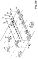
(1) System Appearance
Referring first to Fig. 1, there is depicted an external
appearance of an automatic debiting system according to an
embodiment of the present invention, particularly, in the vicinity
of first and second gantries. This embodiment includes no
tollgates. In place of the tollgates there are provided a first
gantry 44 and second gantry 46 each spanning a plurality of lanes
(six lanes are shown). That is, the system of this embodiment
is carried out on a main road without providing any interchanges.
Naturally, the present invention may also be applied to a single-lane
road.
Vehicles 48 are free lane traveling from the upper left of
the diagram toward the lower right. The first 44 and second 46
gantries are disposed upstream and downstream, respectively, in
the advancing direction of the vehicles 48. The distance between
the first 44 and second 46 gantries is determined depending on
the legal speed limit of the vehicles 48 to be detected. More
specifically, for at least vehicles 48 traveling slower than the
legal speed limit, the distance is so set as to complete processing
such as debiting, debiting confirmation, and illegal vehicle
identification by the time the vehicles 48 pass under the second
gantry 46 after the passage under the first gantry 44.
On the spanning portion of the first gantry 44 are
arranged debiting antennas 50 and enforcement cameras 52. The
debiting antennas 50 are each provided for each of the lanes, and
communicate for debiting with the vehicles 48 (more precisely,
with their IU's 62 which will be described later) traveling on
the corresponding lanes. The enforcement cameras are each used
to photograph license plates of the vehicles 48 traveling on the
lane. As shown, the number of the enforcement cameras to be
arranged may be for example 2n - 1 for n lanes (n: natural
numbers). Furthermore, the object to be photographed is not
restricted to the license plate. That is, to identify the type
of a vehicle, parts other than the license plate may be photographed.
Alternatives may include a front or rear view of the
vehicle, or the vehicle driver. Such arrangement of the
enforcement cameras 52, so there are more cameras than lanes,
will ensure a substantially enhanced horizontal resolution by
integrating all the enforcement cameras 52 irrespective of a
reduced number of pixels in the horizontal direction of individual
enforcement cameras 52.
Together with lighting units 54 not shown in Fig. 1, the
enforcement cameras 52 are positioned, for example, 5.7 meters
above the surface of the road (see Fig. 3). The enforcement
cameras 52 and associated lighting units 54 are located, for
example, 0.5 meters downstream from the debiting antennas 50.
Although not shown, the debiting antennas 50 are directed directly
below or slightly upstream for radio communication with the
IU's 62. The enforcement cameras 52 are arranged in such a
manner as to be able to photograph license plates of the vehicles
48 which have passed over loop coils 60 described later. More
specifically, depressions of the enforcement cameras 52 are so
set that the license plates of the vehicles 48 enter capture
zones 500 at a point of time after the vehicles 48 have passed
over the loop coils 60. It is to be noted that the arrangement
positions of the enforcement cameras 52 must be determined depending
on the positions of the loop coils 60, etc., and the
speeds of the vehicles 48. Accordingly, the enforcement cameras
52 may possibly be provided on the second gantry 46. The lighting
units 54 throw light onto at least their respective camera
capture zones 500.
On the spanning portion of the second gantry 46 are
debiting confirmation antennas 56 and line scanners 58. In the
same manner as the debiting antennas 50, the debiting
confirmation antennas 56 are individually associated with each
of the lanes, and communicate for debiting confirmation with the
IU's 62 of the vehicles 48 traveling on the corresponding lanes.
In order to eliminate dead spots, as will be described later, the
number of the line scanners 58 to be arranged is n + 1 for n
lanes. As is apparent from Fig. 3, the debiting confirmation
antennas 56 and the line scanners 58 are disposed at the same
level as the debiting antennas 50 above the surface of the road.
Communication zones 502 of the debiting confirmation antennas 56
are also set so as to allow communication with the IU's 62 on the
vehicles 48 at a point of time after the vehicles 48 have passed
over the loop coils 60.
Arranged on the road side are the loop coils 60 which are
coils embedded in the ground and whose embedded positions are
indicated by rectangular frames in Fig. 1. In response to the
passage of the vehicles 48 (more generally, magnetic materials)
thereover, inductances of the loop coils 60 vary. Thus, the
passage of the vehicles 48 can be detected by detecting changes
of voltage amplitudes or phases which may appear in the outputs
of the loop coils 60 in accordance with variations of inductances
while supplying alternating signals into the loop coils 60. The
loop coils 60 are embedded at predetermined points between the
first gantry 44 and the second gantry 46, each lane being embedded
with two or more loop coils. For example, three loop coils
60 may be disposed within one lane as shown in Fig. 4, or four
loop coils 60 may be placed as shown in Fig. 5. The use of such
a multiplicity of loop coils 60 for each lane will contribute
effectively to detection of vehicle passage positions at higher
resolutions in a lane crossing direction. In other words, by
detecting which loop coils 60 have their outputs varied, it is
possible to detect the passage positions of vehicle 48 at a high
resolution. Moreover, based on patterns of variations in outputs
of the loop coils 60, it is possible to recognize the type of the
vehicle 48 which has passed over those loop coils 60. It will
be appreciated that the loop coils 60 may be embedded on the
downstream side of the second gantry 46.
A line 64 is further provided on the road side, and this
can be used as an alternative to the loop coils 60. The line 64
is composed of an alternate pattern of black-and-white at predetermined
intervals. The line scanners 58 are disposed on the
second gantry 46 in such a manner that they are capable of photographing
the line 64. In the absence of vehicles 48 on the line
64, images photographed by the line scanners 58 show the black-and-white
pattern. When the vehicles 48 pass across the line 48,
the black-and-white pattern of the images will be obscured.
Therefore, from the state of this observing, it is possible to
recognize the passages of the vehicles 48, passage positions, and
the types of vehicles. Also, a difference in reflectance between
the "black" and "white" portions of the pattern can be utilized
to perform calibrations for the implementation of detection
independent of environmental factors.
The line 64 extending across the lanes is formed, for
example, of paint of alternate black and white at predetermined
intervals. This will contribute to inexpensive formation of the
line 64, but will instead require relatively frequent maintenance
(such as repainting). Alternatively, the line 64 may be
formed, for example, of ceramics plates or tiles. This will
lead to longer duration than the paint and save labor associated
with maintenance. Also, a difference in reflectance between
white tiles, etc., and the surface of the road is usually larger
than the difference in reflectance between the black and white
paint, and hence black tiles, etc., need not be employed. In
addition, the line 64 may be comprised of reflectors. Due to
larger reflectance, the reflectors will more positively ensure
effects similar to the case of the tiles and the like. In addition,
the line scanners 58 may be fitted with lighting units and
receive light reflected from the line 64.
The line scanners 58 are positioned in such a manner as
shown in, for example, Figs. 6 and 7 where four line scanners
58 in total are provided for three lanes. With the number of
line scanners 58 being n + 1 for n lanes in this manner, the
vicinities of lane separating lines would be allowed to fall
within the capture zones 504. In the example of Figs. 6 and 7,
the line scanners 58 are each capable of wide-angle photographing,
and adjoining line scanners 58 have overlapped capture zones
504. The line scanners 58 at two extreme ends are positioned
apart from shoulders approximately 1.1 meters corresponding to
the width of the motorcycle plus slight margins. Such an arrangement
of the line scanners 58 will allow accurate detections
of motorcycles traveling beside a vehicle of larger height, such
as a double-decker bus.
Disposed at the side of the road is a local controller 66
serving to control the equipment mounted on the first 44 and
second 46 gantries, and making use of this equipment to obtain
transaction reports therefrom. The local controller 66 receives
commands from a system central controller 68 (see Fig. 8) situated
some distance away and transmits the transaction reports to
the system central controller 68.
(2) Functions of System Components
Referring to Fig. 8 there is depicted a functional
configuration of the local controller 66 for three lanes. In
the case of an increased number of lanes, additional components
are correspondingly provided. For simplicity of representation,
a single local controller 66 is provided although in the actual
system a plurality of local controllers 66 are typically under
the control of one system central controller 68.
The local controller 66 comprises an antenna controller
(ANTC) 70 for controlling debiting antennas 50. The debiting
antennas 50 are individually provided for each of the lanes, and
therefore three debiting antennas 50 are required for the three
lanes. The debiting antennas 50 are each used to communicate
with the IU 62 mounted on a vehicle 48 for the purpose of
debiting. For communication with the IU 62, the ANTC 70 receives
commands from a general control section 7. The ANTC 70
processes information obtained as a result of the communication
and then supplies it to the general control section 72.
The IU 62 has a configuration, by way of example, such as
shown in Fig. 9. The IU 62 is a unit attached to a windshield
(for example, below a rear view mirror) of the vehicle 48. As
shown, the IU 62 includes an antenna 74, a radio section 76, a
reader/writer 78 and a control section 80. The antenna 74 is an
antenna for radio communication with the debiting antennas 50 and
with debiting confirmation antennas 56. Using the antenna 74,
the radio section 76 performs signal communication with the local
controller 66. The reader/writer 78 is used to write information
into an IC card 82 called a smart card and read information
from the smart card 82. In response to power-on, etc., the
control section 80 executes mutual authentication between the
smart card 82 and the IU 62, and then controls the operation of
the IU 62. In the case where the IU 62 is additionally provided
with a display, subsequent to debiting confirmation communication,
the control section 80 allows the balance of the smart card
82 to appear on a screen of the display.
Referring back to Fig. 8, the local controller 66
comprises a loop-type vehicle detection section 84. The loop-type
vehicle detection section 84 includes three loop-type
vehicle detection units 86, each corresponding to each of the
lanes. The loop-type vehicle detection units 86 each perform
processing, upon vehicle detection, by use of loop coils 60
embedded in the corresponding lanes. The loop-type vehicle
detection units 86 each serve to detect that the vehicle 48 has
passed over the associated loop coils 60 and feed the results to
the general control section 72.
Fig. 10 depicts a functional configuration of the loop-type
vehicle detection unit 86. For simplification of representation,
the configuration is shown corresponding to one loop coil 60.
In the loop-type vehicle detection unit 86, alternating current
signals output from an oscillation section 88 are power amplified
through a power amplifier section 90 and then supplied to the
loop coil 60. In response to the passage of the vehicle 48 over
the loop coil 60, the inductance of the loop coil 60 is increased,
resulting in a raised voltage at both ends of the loop
coil 60. In parallel with the loop coil 60 a detection resistor
92 is connected, by which a variation in the inductance of the
loop coil 60 is detected in the form of a change in voltage. The
results of detection by the detection resistor 92 are processed
by a detector controller (DETC) 94, and then supplied to a
couple of comparators 96 and 98. The comparators 96 and 98
compare two respective thresholds which have been set at values
different from each other with the output of the DETC 94. The
results of comparison are transferred as signals indicating the
passage of the vehicle 48 to the general control section 72.
Hereinafter, the thresholds associated with the comparators 96
and 98 are referred to as high sensitivity and low sensitivity
thresholds, respectively. Similarly, the results of comparison
associated with the comparators 96 and 98 are referred to as high
sensitivity and low sensitivity outputs. It is to be appreciated
that a variation in inductance may be detected as a change in
phase although it is detected as a change in voltage in the
circuit of this diagram.
The local controller 66 depicted in Fig. 8 further
comprises a line-type vehicle detection section 100. Similar
to the loop-type vehicle detection section 84, the line-type
vehicle detection section 100 is means for detecting the passage
of the vehicle 48 and supplying the results to the general control
section 72.
Fig. 11 depicts a functional configuration of the line-type
vehicle detection section 100. As shown, the line-type
vehicle detection section includes a line scanner controller 102,
line scanner data read sections 104, a vehicle detection section
106, a calibration section 108, a line scanner iris control
section 110, and an interface section 112.
The line scanner controller 102 supplies power to the line
scanners 58 and imparts clocks thereto for their operations.
In response to the clocks, the line scanners 58 photograph a line
64 and supply resultant image signals to the corresponding line
scanner data read sections 104. The line scanner data read
sections 104 convert the image signals into digital data, and
store them in internal image memories. On the basis of the data
stored in the image memory, the vehicle detection section 106
performs the processing on detection of the vehicle 48. Transferred
to the general control section 72 through the interface
section 112 is thus obtained information such as, for example,
the presence or absence of the passage of the vehicle 48, and if
present, the width of the vehicle 48 which has passed thereover
and its passage positions (in lane crossing direction).
The general control section 72, if needed, issues commands
via the interface section 112 to the calibration section 108.
In compliance with the commands from the general control
section 72, the calibration section 108 reads data from the image
memories of the line scanner data read sections 104. In accordance
with a black-and-white pattern contained in the read data,
the calibration section 108 issues commands to the line scanner
iris control section 110 which in turn controls the iris of the
line scanners 58 in response to the commands. Irrespective of
variations in sunshine, etc., this control allows data showing
the black-and-white pattern to be formed in the image memories of
the line scanner data read section 104.
The local controller 66 further comprises a vehicle
photography section 114 for the processing and control
pertaining to enforcement cameras 52, and an image compression
section 116 for the data compression of images obtained by the
photography. The vehicle photography section 114 includes image
memory/plate detection units 118 provided in correspondence to
the enforcement cameras 52, a control section 120 for controlling
the image memory/ plate detection units 118, and an image interface
section 122 consisting of an interface associated with image
output. The image compression section 116 includes image compression
units 124 provided in correspondence to the enforcement
cameras 52.
In response to the detection of passage of the vehicle 48
by the loop-type vehicle detection section 84 or the line-type
vehicle detection section 100, the general control section 72
issues a shutter command to one of the enforcement cameras 52,
through a corresponding image memory/plate detection unit 118, to
initiate photography of the license plate by the enforcement
cameras 52. In order to ensure that the license plate of the
vehicle 48 is substantially centered on a photograph, the general
control section 72 determines which enforcement camera 52 is to
receive the shutter command, depending on the passage position
of the vehicle 48 to be detected by the loop-type vehicle detection
section 84 or the line-type vehicle detection section 100.
This procedure will be described in detail later.
An image obtained by the photography is stored in the
image memory of the corresponding image memory/ plate detection
unit 118. The image memory/ plate detection unit 118 extracts
the image of the license plate of the vehicle 48 from images
stored in its image memory, and supplies the thus extracted
license plate image via the image interface section 122 to the
corresponding image compression unit 124. The control section
120 controls the image processing (including the extraction of
the license plate image) in the image memory/ plate detection
unit 118, and repeatedly imparts shutter commands to the
specific enforcement camera 52 until a preferred license plate
image is obtained. The image memory/ plate detection unit 118
has sufficient capacity to store a plurality of images produced
in response to a series of shutter commands so as to allow a
plurality of vehicles 48 coming into its visual field (camera
capture zone 500) to be photographed. The image compression
unit 124 performs data compression of the image supplied from the
corresponding image memory/ plate detection unit 118, and then
delivers the thus compressed image to the general control section
72 which in turn sends the compressed image to the system central
controller 68.
The local controller 66 further comprises an antenna
controller (ANTC) 126 for controlling the transmission/reception
of signals by the debiting confirmation antennas 56.
The ANTC 126 communicates by radio with the IU 62 on the vehicle
48 to confirm whether or not the debiting has been positively
executed or not. In response to the result of this confirmation,
the general control section 72 sends necessary information
to the system central controller 68. In case the execution of
debiting has been confirmed, for example, the license plate image
produced by the enforcement camera 52 is transferred as an evidential
photograph of a violation together with predetermined
data to the system central controller 68.
The local controller 66 additionally comprises a lighting
control section 128 and an environment control section 130. The
lighting control section 128 permits the lighting units 54 to
light up the surface of the road when the illuminance on the
surface of the road goes down to a predetermined value or below,
and turns off the lighting units 54 when it goes up to the
predetermined value or over. This will ensure a preferred
photography of the license plate irrespective of weather or the
time of day or night. The environment control section 130
detects ambient temperatures and humidities, and imparts the
results to the general control section 72. In response to the
results of detection, the general control section 72 controls the
components of the local controller 66 so that they function
normally and properly. Should the environmental conditions
worsen to such a degree that the components do not work properly
or to a degree allowing the possibility of improper functioning,
the general control section 72 reports that fact to the system
central controller 68.
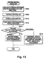
(3) Summary of Debiting Processing
Referring to Figs. 12 and 13, there are depicted a flow of
overall processing and a schematic flow of debiting processing,
respectively, of this embodiment.
In this embodiment, as shown in Fig. 12, the system
central controller 68 first issues a toll collection start command
to each of the local controllers 66 (1000). At the same
time, information required for debiting processing is also transmitted
from the system central controller 68 to the local controllers
66. Upon receipt of these commands and information,
the local controllers 66 carry out the debiting processing
(1002). Each of the local controllers 66 repeats the debiting
processing until it receives a toll collection end command from
the system central controller 68 (1004).
The debiting processing executed in each of the local
controllers 66 generally follows the flow depicted in Fig. 13.
Under the control of the ANTC 70, the debiting antennas 50
issue a call by radio to the vehicle 48 which is just about to
pass under the first gantry 44. As long as a normal IU 62 is
mounted on the vehicle 48 just about to pass under the first
gantry 44, the IU 62 performs radio transmission of predetermined
control information. The control information transmitted from
the IU 62 includes information on, for example, the type of the
vehicle, the owner, the license number, and an identification
code appropriate to the IU 62. Such information is held in the
control section 80 or alternatively is read from the smart card
82 by means of the reader/writer 78. The debiting antennas 50
receive the control information from the IU 62, and then transmit
the information to the general control section 72. The general
control section 72 determines the sum of the toll to be collected
using the information on the type of the vehicle out of the
control information received from the IU 62. While specifying
the IU 62 to be received in accordance with the identification
code appropriate to the IU 62 out of the received control information,
the general control section 72 transmits the thus determined
sum to the vehicle 48 side through the debiting antennas
50. At that time, the general control section 72 may search a
valid list (a list of IU's which have been sold on the market)
and a black list (a list of habitual debiting violators, etc.) in
accordance with the identification code appropriate to the IU 62
or the like. The IU 62 records the sum of the toll to be collected
on the smart code 82 and it is then transmitted through
the debiting antennas 50 (for instance, the sum may be deducted
from an available limit set on the smart card 82). This brings
the debiting processing by use of the first gantry 44 to a termination
(1006). This processing must be completed at the latest
before the vehicle 48 reaches the communication zones 502 of the
debiting confirmation antennas 56.
Subsequently, the local controller 66 detects the vehicle
48 by using the loop coils 60 or the line scanners 58 (1008,
1010), and then produces a static image of the rear (more
restrictively, a portion mounted with the rear license plate)
of the vehicle 48 (1012). The loop-coils 60 and the line scanners
58 both being means for detecting the vehicle 48, may either
be solely employed although the cooperation of the two will
ensure improved reliability in the vehicle detection. As an
alternative to these means, use may be made of, for example,
detectors utilizing the principle of triangulation.
Using the debiting confirmation antennas 56 mounted on the
second gantry 46, the local controller 66 communicates with the
IU 62 on the vehicle 48. More specifically, the local
controller 66 requires the IU 62 to send information for the
confirmation of debiting, whereupon if normal, the IU 62 responds
to this (1014). When the execution of normal debiting is
confirmed by the communication through the debiting confirmation
antennas 56, the general control section 72 transmits the fact
that the debiting has been normally executed along with the data-compressed
license plate image (1016) to the system control
controller 68. Conversely, in the case where the IU 62 makes no
response or where, regardless of a response from the IU 62, the
contents of the response indicate incompletion of the debiting
(e.g., when exceeding the available limit set on the master card
82), the general control section 72 regards the vehicle 48 mounted
with this IU 62 as an illegal vehicle, and transmits the data-compressed
license plate image as the image of the illegal vehicle
together with the data indicating that the debiting has
resulted in an abnormal termination (1018).
(4) Principle of Vehicle Detection with Loop Coils
As describe above, this embodiment includes the loop coils
60 and the line scanners 58 as means of vehicle detection.
Description will now be given of a principle of the vehicle
detection by means of the loop coils 60.
When a vehicle 48 travels along the road, the front of
the vehicle 48 (more concretely, a portion of the front wheel
axle occupying a relatively large part of the magnetic mass of
the vehicle 48) approaches the loop coils 60 at a certain point
in time (1008) as indicated by a solid line in Fig. 14(a). In
response to this, the inductance of the loop coil 60 varies with
the result that an output waveform of the DETC 94 rises (timing
t0 of Fig. 14 (b) to (d)). It is to be noted that for simplicity
of description, dissimilar to Fig. 10, a single comparators
is assumedly provided herein to identify the output waveform of
the DETC 94 with an output waveform of the comparator.
When the vehicle 48 advances to bring its IU 62 into the
debiting confirmation antenna communication zones 502 as indicated
by ellipses in Fig. 14(a), communication with the IU 62 can
be established by way of the debiting confirmation antennas 56.
The local controller 66 issues a call for debiting confirmation
to the IU 62. In response to the call issued through the debiting
confirmation antennas from the local controller 66, the IU 62
reads the debiting information stored in the smart card 82 by
means of the reader/writer 78 and sends it through the radio
section 76 to the local controller 66. The debiting information
is received by the local controller 66 through the debiting
confirmation antennas 56.
With further advancement of the vehicle 48, the rear of the
vehicle 48 (more concretely, a portion of the rear wheel axle
occupying a relatively large part of the magnetic mass of the
vehicle 48) leaves the loop coils 60 as indicated by a dotted
line in Fig. 14(a). In response to this, the output of the DETC
94 falls (1010). In Fig. 14 (b) to (d), the fall timing is
designated by t11, t12, and t13 for bus/ large-sized truck,
automobile/ small-sized truck, and motorcycle, respectively. In
synchronism with this fall timing, the general control section 72
imparts shutter commands to the enforcement cameras 52 (1012).
The image memory/ plate detection unit 118 extracts license
plate images from the images photographed by the corresponding
enforcement camera 52.
When the vehicle 48 comes into the camera capture zone 500
indicated by a rectangle in Fig. 14(a) and brings the license
plate into a preferred position, the license plate image
extraction processing by the image memory/ plate detection unit
118 is completed, in response to which the photography of the
license number by use of the enforcement camera 52 comes to an
end.
In the case of detecting the vehicle 48 with the loop coils
60, the types of vehicle can be identified by the execution of
two kinds of comparison as shown in Fig. 10. When the vehicle
48 approaches the loop coil 60 as indicated by a solid line in
Fig. 15(a), an output waveform of the DETC 94 gradually rises as
shown in Fig. 15(b). Providing that a threshold associated with
the comparator 96 (high sensitivity threshold) is set to be
smaller than a threshold associated with the comparator 98 (low
sensitivity threshold), an output waveform (high sensitivity
output waveform) of the comparator 96 shown in Fig. 15(c) will
rise earlier than an output waveform (low sensitivity output
waveform) of the comparator 98 shown in Fig. 15(d). In the
process of the advancement of the vehicle 48 into a position
indicated by a broken line in Fig. 15(a), the output waveform of
the DETC 94 gradually falls as shown in Fig. 15(b). In this
process, the low sensitivity output waveform will fall earlier
than the high sensitivity output waveform.
Accordingly, the use of two kinds of threshold in this
manner will bring into existence both the high sensitivity output
waveform rising during the time tH and the low sensitivity output
waveform rising during the time tL (tL< tH). For the vehicle
having a smaller magnetic mass such as a motorcycle, due to
smaller variation in the inductance of the loop coil 60, the peak
of the output wave of the DETC 94 is reduced, resulting in tL=0.
In other words, no low sensitivity output waveform appears. It
is thus possible to identify the types of vehicle by collectively
judging the high sensitivity and low sensitivity output waveforms
in the general control section 72. The results of identification
of the types of vehicle are used for the confirmation of debiting
or the specification of illegal vehicles. It is to be appreciated
that the present invention is not limited to the two kinds
of threshold.
As depicted in Figs. 4 and 5, a plurality of (e.g., three
or four) loop coils 60 are provided for each of the lanes. It
is thus possible to recognize the position and lane on which the
vehicle 48 travels by judging, in the general control section 72
the loop coil 60 over which the vehicle 48 has passed. Given
that the traveling vehicle 48 is a motorcycle, an output waveform
showing the presence of the vehicle 48 appears in only one of,
e.g., three loop coils placed for each lane. Therefore, if one
of the loop coils 60 is exclusively subjected to the variation in
output, it is detected that the motorcycle has passed over this
loop coil 60, enabling not only the position of passage but also
the type of vehicle to be recognized.
Also, in the case of plurality of vehicles 48 traveling side
by side, no variations in outputs will appear in the loop coils
disposed between the plurality of vehicles as long as there is
some degree of spacing between the vehicles, whereby these vehicles
can be distinguished from one another.
Provided that a plurality of (e.g., three) motorcycles are
traveling on the same lane, an output waveform representing the
presence of a vehicle may possibly appear in all of a plurality
of (e.g., three) loop coils 60. However, since the use of two
kinds of threshold enables the types of vehicle to be identified,
the traveling of the plurality of motorcycles on the same lane
can be distinguished from the traveling of, e.g., a single
automobile which may cause an output waveform representing the
presence of a vehicle in the three loop coils 60.
In addition, the timing at which to cease photographing by
the enforcement camera 52 is given by the completion of extraction
of the license plate images by the image memory/ plate
detection unit 118, whereupon it is influenced to a lesser degree
by off time delay indicated as t in Fig. 14(b) to (d).
For comparison, the photographing of the license plate takes
place once or a predetermined number of times in response to the
fall in the output of the loop coil 60. In such a configuration,
with an assumption of speed of the vehicle 48 at a certain
speed, setting must be made for both the positions of the loop
coils 60 and the angles of depression of the enforcement cameras
52 so as to ensure preferred photographing of the license plate
of the vehicle 48 traveling at the assumed speed. A speed of the
vehicle 48 remarkably higher than the assumed speed would result
in missing of preferred photographing timing due to the traveling
of the vehicle 48 during the delay time Δt. Values of the delay
time delta Δt depend on the types of vehicle.
Such inconvenience will disappear by virtue of this embodiment
in which the commencement of photographing is given by
the fall in the output of the loop coil 60 and the conclusion
thereof is given by the completion of the extraction of the
license plate images. More specifically, the capture zones 500
of the enforcement cameras 52 are separated from the positions of
the loop coils 60 so as to allow for the maximum of the delay
time Δt, thereby ensuring accurate photographing of the license
plates irrespective of the speeds of the vehicles 48 ranging from
0 to 120 km/hour and irrespective of the capture zones 500 of the
enforcement cameras 52 extending four meters in the direction of
length of the road.
Further, this embodiment makes use of the results of detection
by the loop coils 60, which will be described hereinafter,
to regulate the timing at which to commence photographing by the
enforcement cameras 52. Thus, regardless of the speeds of the
vehicles the license plates can be photographed at appropriate
timing.
(5) Principle of Vehicle Detection with Line Scanners
Description will be given of a principle of vehicle detection
using the line scanners 58. Referring to Fig. 16, there are
depicted variations in the output of the line scanner 58 caused
by the passage of the vehicle 48 over the line 64.
As heretofore explained, the line 64 is photographed by
the line scanners 58, and the resultant image signals are read,
through conversion into digital data, into the image memories of
the line scanner data read sections 104. In accordance with the
data, the calibration section 108 controls the line scanner iris
control section 110 to attain the data correspondent with the
black-and-white pattern constituting the line 64. In the absence
of any vehicles over the line 64, such a calibration will
result in the data as depicted in Fig. 16 (b).
In the presence of vehicles 48 on top of the line 64 as
shown in Fig. 16 (a), data are obtained correspondent with colors
of the vehicles 48. Assume first that the colors of the vehicles
48 crossing the line 64 are white or other colors presenting
reflection analogous to white. If the colors of the vehicle 48
have high reflectivities in this manner, then the line scanners
58 will detect data of these vehicles 48 as the same data as the
white pattern. In other words, from the areas corresponding to
the vehicles 48, the line scanners 58 will receive luminance
levels approximate to the level of white.
On the contrary, assume that the colors of the vehicles 48
crossing the line 64 are black or other colors presenting the
reflection analogous to black. If the colors of the vehicles
48 have low reflectivities in this manner, the line scanners 58
will detect data of these vehicles 48 as the same data as the
black pattern. In other words the line scanners 58 will receive
luminance levels approximate to the level of black from the areas
corresponding to the vehicles 48
Thus, the vehicles 48 in white or other colors analogous
thereto would result in data as shown in Fig. 16(c) diagram is
wrong, whereas the vehicles 48 in black or other colors analogous
thereto would result in data as shown in Fig. 16(d). More specifically,
the data for the "white" vehicles involve a disturbance
such that portions that are originally black in the absence
of the vehicles 48 result in white, whereas the data for the
"black" vehicles involve a disturbance such that portions that
are originally white in the absence of the vehicles 48 result in
black.
The vehicle detection section 106 detects disturbances
involved in the data obtained, and on the basis of the results
performs detection of vehicles 48, detection of positions
thereof, and judgment of the types of the vehicle. Firstly, the
detection of the presence of disturbances in the data will enable
the passage of the vehicles 48 to be recognized. Secondly, the
positions on the data where disturbances have occurred will
enable passage positions of the vehicles 48 to be recognized.
Thirdly, the widths of disturbances will allow the identification
of the types of vehicles. Fourthly, tracking with time of the
occurrence of disturbances will enable the passage of a plurality
of vehicles 48 traveling in tandem to be detected individually
for each of the vehicles. Fifthly, a plurality of vehicles 48
traveling side by side can be separately detected. The enforcement
cameras may receive shutter commands in response to the
detection of passage of the vehicles 48 by the vehicle detection
section 106.
Accordingly, this embodiment will ensure accurate detection
of vehicles 48 by means of the line scanners 58. In addition,
iris control (calibration) by the feedback of data along with the
use of the black and white pattern as the line 64 will contribute
to preferred detection of the vehicles 48 of intermediate color,
and to resistance to variations in environment such as sunshine.
Put more clearly, suppose a single white line in place of
line 64 for the sake of comparison. In such a configuration, the
passage of the vehicles 48 over the white line will be detected
by partial depressions in luminance of the signals obtained by
the line scanners 58. The depressions in luminance are however
caused by not only the bodies of the vehicles 48 but also shades
thereof. Moreover, the manner in which the shades appear vary
depending on the position of the sun, the latitude, the season,
etc. The degree of the depression in luminance also depends on
the color of the vehicle 48. It is therefore difficult to ensure
accurate detection of the passage of the vehicle irrespective of
the execution of calibration. It is also difficult to set a threshold
for use in making image signals into binary signals. The
same applies to the configuration of a single black line.
For further comparison, suppose a configuration having no
line. In such configuration, due to uneven reflectivity of the
surface of the road, accurate detection of the passage of the
vehicle 48 is difficult to perform irrespective of the execution
of calibration.
This embodiment eliminates the above inconveniences by the
provision of a pattern of alternate "white" having a high
reflectivity and "black" having a low reflectivity. For instance,
the reflectivity of the "black" paint is in the order of
10-3 that of the "white" paint, and this relationship is not
influenced by the level of sunshine or other environmental factors.
Accordingly, the appropriate execution of the calibration
will ensure accurate detection of the vehicle 48 independent of
variations in environmental conditions. Thus, irrespective of
outdoor use of this embodiment system, which may be subjected to
severe environmental conditions, accurate detection of the passage
of the vehicle 48 is constantly ensured. Even though the
color of the vehicle 48 is an intermediate one, the presence of
the vehicle can be detected as the disturbance of either white or
black.
As depicted in Figs. 6 and 7, the number of line scanners 58
to be provided in this embodiment is n + 1 for n lanes. The
line scanners 58 are each fitted with an wide-angle lens, and
visual fields of the adjoining line scanners 58 overlap each
other. Accordingly, even in the case of a vehicle (e.g., a
motorcycle) having a small height traveling between vehicles
(e.g. double-decker buses) of large heights, it is possible to
distinctly identify these vehicles. Namely, no dead spots appears.
In addition, the use of the wide-angle lens will minimize
the number of the line scanners 58 to be used.
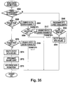
(6) Details of Vehicle Detection with Loop Coils
Figs. 17 to 29 illustrate procedures of vehicle detection
processing by use of the loop coils 60, in particular, of
vehicle center position judgment processing in the road crossing
direction, and Figs. 30 to 37 depict the flows of these
procedures. Implemented by the processing shown in these
diagrams is a function to properly separate a plurality of
vehicles 48 traveling side by side or to properly separate the
plurality of vehicles 48 traveling in tandem with narrow
distances therebetween, as well as a function to properly detect
passage positions in the width direction of the road. Also
implemented is a measure to deal with a wider range of speeds
since depending on the speeds of the vehicles 48, the vehicle
photography section 114 is capable of controlling the time required
up to the commencement of photographing by the enforcement
cameras 52 from the point of time of vehicle passage detected by
the loop coils 60. Furthermore, the utilization of low
sensitivity and high sensitivity outputs of the loop coils 60, as
well as the approximation to a quadric curve, ensures accurate
execution of judgment of vehicle types and judgment of vehicle
center positions.
The vehicle center position judgment processing in this
embodiment comprises procedures for judging, upon the entry of a
vehicle 48 into the zone of the loop coils 60, what type the
vehicle 48 is and where the vehicle center position is (in the
direction crossing the road), the processing being generally
implemented by following three procedures. In the following
description, an i-th loop coil 60 is designated by Li, and singly
hatched in the diagrams is a period of time during which only the
high sensitivity output of the loop coil is on, while doubly
hatched is a period of time during which both the high sensitivity
and low sensitivity outputs thereof are on.
i. First Procedure
A first procedure includes a step of temporarily regarding
the vehicle 48 which has entered the zone of a loop coil 60 as a
motorcycle, and estimating that its vehicle center position lies
on this loop coil 60. Entrance of the vehicle 48 into the zone
of the loop coil 60 can be recognized by the fact that the high
sensitivity output of each loop coil 60 has turned on. That
is, in the first procedure, the general control section 72 of the
local controller 66 when the high sensitivity output has turned
on temporarily estimates that a motorcycle has entered the zone
of the loop coil 60 without considering whether the vehicle which
has entered the loop coil zone is actually the motorcycle or an
automobile. In the following description, the term "motorcycle"
refers to a vehicle having a narrow width not allowing outputs of
a plurality of loop coils 60 to simultaneously occur, for example,
a two-wheeled vehicle. Also, the term "automobile" refers
to a vehicle having a wide width allowing outputs of a plurality
of loop coils 60 to simultaneously occur, for example, a four-wheeled
vehicle.
For example, as shown in Fig. 17, assume that at substantially
the same time or in rapid sequence the (i-1)th loop coil
Li-1, i-th loop coil Li, and (i+1)th loop coil Li+1 have turned
on. In this case, it is impossible to identify from only the
information shown, whether a single automobile spanning the loop
coils Li-1, Li and Li+1 has entered the loop coil zones or three
motorcycles have separately enter the zones of the loop coils Li-1,
Li, and Li+1. Thus, the general control section 72 temporarily
assumes that three motorcycles have individually entered the
zones of the loop coils Li-1, Li, and Li+1 (first procedure).
At the same time, the general control section 72 estimates
that vehicle center positions of these imaginary motorcycles lie
on positions where the loop coils Li-1, Li, and Li+1 are embedded.
In other words, the general control section 72 estimates
that the vehicle center positions of the vehicles 48 which have
caused the high sensitivity outputs of the loop coils Li-1, Li,
and Li+1 to turn on will be coincident with positions Cin-, Cin,
and Cin+ indicated respectively by a white circle, a white diamond
and a black diamond in the diagram.
ii. Second Procedure
A second procedure includes steps of confirming whether or
not it was correct that the vehicle was temporarily estimated to
be a motorcycle in the first procedure and judging the first
estimation is judged to have been incorrect, that the vehicle is
an automobile. More specifically, in the case for example,
where detection data as shown in Fig. 17 are obtained from each
loop coil, then the general control section 72 performs judgment
processing for identifying whether a single automobile spanning
the loop coils Li-1, Li, and Li+1 has entered the loop coil zones
or three motorcycles have individually entered the zones of the
loop coils Li-1, Li, and Li+1. For this judgment, use is made of
the low sensitivity output of each loop coil 60.
The low sensitivity output of the loop coil 60 is
permitted to turn on only when the magnetic mass of the vehicle
passing over the loop coil 60 is sufficiently large, but
remains off when it is small. Accordingly, in general, if the
vehicle passing over the loop coil 60 is an automobile, the low
sensitivity output of the loop coil 60 turns on, but remains
off if it is a motorcycle. Thus, if the low sensitivity output
of the loop coil Li has turned on as shown in Fig. 18, then
the general control section 72 judges that an automobile has
passed over the loop coil Li. On the contrary, providing that
the high sensitivity output has turned off with the loop coil
Li remaining off as shown in Fig. 19, the general control
section 72 judges that the automobile has passed over the loop
coil Li.
iii. Third Procedure
Through the execution of the first and second procedures,
(1) the positions of the loop coils 60 whose high sensitivity
outputs have turned on are estimated to coincide with the vehicle
center positions of the vehicles 48 which have entered the zone
of the loop coil 60, (2) a judgment is made that an automobile
has entered zones of the loop coils 60 whose high sensitivity and
low sensitivity outputs have both turned on, and (3) a judgment
is made that motorcycles have entered the zones of the loop coils
60 of which high sensitivity outputs have turned on with the low
sensitivity outputs remaining off. However, these are insufficient
for the judgment of the types of vehicle and vehicle center
positions.
First, upon estimation that two loop coils 60 adjacent or in
close proximity to each other both have their high sensitivity
outputs are both on, suppose that the low sensitivity output of
a first loop coil 60 thereof remains off but the low sensitivity
output of a second loop coil 60 is on. The first loop coil 60
may have caught the entrance that the same automobile as entered
the zone of the second loop coil 60, or otherwise it may have
caught the entrance of quite a different vehicle 48 from that
automobile. Therefore, for the first loop coil 60, inaccuracy
will remain as long as the estimated result in the first procedure
is maintained, namely, the estimation result that motorcycle
has entered the zone of this loop coil 60.
Second, upon the estimation that three loop coils 60 adjacent
or in close proximity to each other all have their high
sensitivity outputs on, suppose that the low sensitivity output
of at least a first loop coil 60 is on. The vehicle 48 caught by
the first loop coil 60 is an automobile (or has at least a high
probability of being an automobile) as has been judged by the
second procedure. Accordingly, the fact the high sensitivity
outputs (as well as the low sensitivity outputs, as the case may
be) of the second and third loop coils adjacent or in close
proximity to the first loop coil are both on may largely arise
from the vehicle 48 caught by the first coil 60. Thus, decision
should be made of the vehicle center position caught by the first
loop coil 60, in view of not only the position where the first
loop coil 60 is embedded but also the positions where the second
and third loop coils 60 are embedded. In other words, merely
defining the position estimated by the first procedure as the
vehicle center position of the vehicle 48 caught by the first
loop coil 60 will still allow inaccuracy. In addition, allowance
must be made for a possibility that the vehicle which has caused
the high sensitivity and low sensitivity outputs of the second
and third loop coils 60 to turn on may not coincide with the
vehicle 48 caught by the first loop coil 60.
Thus, in order to find a true vehicle center position, the
general control section 72 executes a third procedure including
the following contents, using the results of the first and
second procedures while using quadric curve approximation,
etc., if needed.
a) When Judged to be Motorcycle by Second Procedure
Consideration will be first given to the loop coil 60 whose
low sensitivity output has not turned on before its high sensitivity
output turns off after been having turned on. For such
type of loop coils 60, it may be construed that it has caught
the automobile caught by the other loop coils 60 or that it has
caught a vehicle 48 (e.g., a motorcycle) which has not been
caught by the other loop coils 60. This embodiment rigidly
distinguishes both cases by a distance judgment. As depicted in
Figs. 20 and 21, assume that the low sensitivity output of the
loop coil Li has not turned on before its high sensitivity output
turns off after having been turned on. In other words, suppose
it has not yet been judged that the vehicle 48 lying on the loop
coil Li is an automobile before its high sensitivity output turns
off. In this instance, at the time when the high sensitivity
output of the loop coil Li has turned off, the general control
section 72 compares a distance between the loop coil Li and
the other loop coil 60 closest to the loop coil Li1 among
the loop coils 60 for which judgment was made that an automobile
has passed thereover in the second procedure with a predetermined
reference distance Cside. With this distance less than
the reference distance Cside, both the loop coils could be assumed
to have caught the same vehicle 48 (the same automobile in
this case). On the contrary, with this distance exceeding the
reference distance Cside, both the loop coils could be assumed to
have individually caught different vehicles 48.
Assume, for example, the reference distance Cside is set
at a distance 1.5 times the loop coil embedment intervals. As
depicted in Fig. 20, suppose that the other loop coil 60 closest
to the loop coil Li, among the loop coils 60 for which judgment
was made that an automobile has passed thereover in the second
procedure is a loop coil Li-2 having a distance twice the loop
coil embedment intervals relative to the loop coil Li. Since in
this case the loop coil Li is far apart from the loop coil Li-2,
the vehicle 48 which has passed over the loop coil Li is supposedly
different from the vehicle 48 which has passed over the loop
coil Li-2. The general control section 72 detects this fact
from the comparison of the reference distance Cside with the
distance between the loop coil Li and the loop coil Li-2. In
accordance with this detection, the general control section 72
judges that the vehicle 48 which has passed over the loop coil Li
is distinctly different from the vehicle 48 which has passed over
the loop coil Li-2 and that the vehicle center position of the
vehicle 48 which has passed over the loop coil Li lies on the
loop coil L i 60 as indicated by a white diamond and Cin in the
diagram. Since the vehicle 48 which has passed over the loop
coil Li is judged to be a motorcycle in the second procedure,
this will define the type and vehicle center position of the
vehicle 48 which has passed over the loop coil Li.
As depicted in Fig. 21, suppose that the other loop coil
60 closest to the loop coil Vi among the loop coils 60 for
which judgment was made that an automobile has passed thereover
in the second procedure is a loop coil Li-1 having a distance
equal to the loop coil embedment intervals relative to the loop
coil Li. Since in this case the loop coil Li is sufficiently
close to the loop coil Li-1, the vehicle 48 which has passed
over the loop coil Li is assumed to be the very same as the
vehicle 48 which has passed over the loop coil Li-1. The general
control section 72 detects this fact from the comparison of
the reference distance Cside with the distance between the loop
coil Li and the loop coil Li-1. In accordance with this detection,
the general control section 72 judges that the vehicle 48
which has passed over the loop coil Li is the very same as the
vehicle 48 which has passed over the loop coil Li-1 and that the
vehicle center position of the vehicle 48 which has passed over
the loop coil Li assumedly lies on the loop coil L i-1 60 as
indicated by a black diamond and Cin- in the diagram, but on the
position indicated by a white diamond and Cin in the diagram.
From this judgment result both the vehicle center position estimation
result in the first procedure and the vehicle type judgment
result in the second procedure are canceled for the vehicle
48 which has passed over the loop coil Li.
Regarding the vehicle 48 which has passed over the loop
coil Li-2 in the example of Fig. 20 and the vehicle 48 which has
passed over the loop coil Li-1 in the example of Fig. 21 the
judgment result that "the type of the vehicle is an automobile"
obtained by the second procedure is established. However, its
vehicle center position remains unestablished due to the
necessity of taking into consideration both the manner of outputs
of the loop coils 60 adjacent to or in close proximity to the
loop coil Li-2 or the loop coil Li-1 and the possibility that the
vehicle 48 may cause the low sensitivity outputs of a plurality
of loop coils 60 to simultaneously be on. Processing for
definitely deciding this will become apparent from the following
description.
b) When Judged to be Automobile by Second Procedure
With regard to the loop coil 60 whose low sensitivity output
has turned on before its high sensitivity output has turned off
after having been turned on, judgment is made that "the type of
the vehicle 48 which has passed thereover is an automobile" by
the second procedure. Also, for the other loop coils 60 having
distances less than the reference distance Cside relative to such
a loop coil 60, and whose high sensitivity outputs have turned
on, both the vehicle center estimation result in the first procedure
and the vehicle type judgment result are canceled by the
step a) of the third procedure. Thus, as to the loop coil 60
low sensitivity output has turned on before its high sensitivity
output has turned off after having been turned on, there is a
need to establish the vehicle center position of the vehicle 48
which has passed thereover, taking into consideration the embedment
positions of the other loop coils having distances less than
the reference distance Cside relative to such a loop coil 60
and whose high sensitivity outputs have turned on.
For this reason, at the time when the low sensitivity output
has turned off, the general control section 72 corrects the
vehicle center position estimated by the first procedure. The
correction comprises the step of using quadric curve approximation.
This will ensure that the general control section 72 is
capable of more accurately finding the vehicle center position of
the automobile which is passing over the loop coil 60 whose low
sensitivity output has turned on before its high sensitivity
output turns off after having been turned on. It is to be
appreciated that in definitely determining the vehicle center
position by such techniques allowance must be made for the sequence
in which the high sensitivity outputs of the loop coils 60
have turned on.
b1) Case in which the high sensitivity output of the loop coil
Li turns on earlier than the high sensitivity outputs of the
loop coils Li-1 and L1+1:
In general, the center of the vehicle 48 has the most
magnetic mass distributed therearound. Accordingly, the high
sensitivity output of the loop coil 60 whose embedment position
is closer to the vehicle center position turns on previous to
that of the loop coil whose embedment position is farther from
the vehicle center position. For this reason, the high sensitivity
output of the loop coil 60 over which a vehicle 48 has passed
the type of which type has been judged to be an automobile by the
second procedure turns on earlier than the high sensitivity
outputs of the loop coils 60 which have caught the same vehicle
48 among the loop coils 60 adjacent to or in proximity thereto.
It is therefore typically envisaged that the high sensitivity outputs
turn on in the sequence as shown in Fig. 22.
As is clear from this diagram, the high sensitivity output
of the loop coil Li over which a vehicle 48 has passed the type
of which has been judged to be an automobile by the second procedure
is on previous to the high sensitivity output of the loop
coils Li-1 and Li+1 embedded on both sides of the loop coil Li.
In this case, the general control section 72 applies to a quadric
curve the time when the outputs of the three loop coils Li-1, Li,
and Li+1 have turned on (quadric curve approximation). The
resultant quadric curve represents a distribution of the magnetic
mass in the vehicle 48 which is passing over the three loop coils
Li-1, Li, and Li+1. Thus, a peak of the quadric curve (a point
where tangential direction of the quadric curve coincides with
the road crossing direction, which is designated by a white
diamond in the diagram) can be regarded as a position where the
most magnetic mass is commonly distributed, that is, a vehicle
center position. Then, in accordance with the result of the
quadric curve approximation, the general control section 72
corrects the vehicle center position Cin estimated by the first
procedure. That is, the thus obtained quadric curve peak is
employed as an established vehicle center position Cin closer to
the true value.
A mere application of this quadric curve approximation
will be prohibited in the case where both the low sensitivity and
high sensitivity outputs have turned off while leaving either or
both of the high sensitivity outputs of the loop coils Li-1 and
Li+1 off. To compensate for this, the general control section 72
executes the following processing.
As shown in Fig. 23, assume first that both the low sensitivity
and high sensitivity outputs have turned off with
either of the high sensitivity outputs of the loop coils
Li-1 and Li+1 (of Li+1 in the diagram) remaining off.
In this case, among three different times to be originally
applied to the quadric curve approximation, it is difficult to
obtain the time when the high sensitivity output of the loop
coil Li+1 has turned on. Therefore, the general control
section 62 applies to the quadric curve approximation as an
alternative, the time (indicated by white triangle in the
diagram) midway between the time when the low sensitivity output
of the loop coil Li has turned on and the time when it has turned
off. In other words, a value obtained by adding T/2 (T: the time
taken by the time when the low sensitivity output of the loop
coil Li turns off after having turned on) to the time when the
low sensitivity output of the loop coil Li has turned on is used
in the quadric curve approximation. The general control section
72 executes the same processing as above in the case of the
absence of either of the loop coils Li-1 and Li+1 (for example,
when the loop coil Li is a loop coil 60 located at the edge of
the road).
As seen in Fig. 24, assume that the low sensitivity and
high sensitivity outputs of the loop coil Li have turned off
with the outputs of the loop coils Li-1 and Li+1 remaining off.
In this case, without performing the quadric curve approximation,
the general control section 72 establishes the vehicle center
position Cin (indicated by white diamond in Fig. 24) estimated by
the first procedure intact as the vehicle center position Cin.
b2) Case in which the high sensitivity output of either the loop
coil Li-1 or Li+1 turns on earlier than or simultaneously with
the time when the high sensitivity output of the loop coil Li
turns on:
As stated in the above b1), the high sensitivity output of
the loop coil 60 whose embedment position is closer to the vehicle
center position generally turns on before that of the loop
coil 60 whose embedment position is farther from the vehicle
center position. Depending on the shapes or the widths of the
vehicles 48, however, the high sensitivity output of the loop
coil 60 whose embedment position is farther from the vehicle
center position may possibly turn on earlier than or simultaneously
with that of the loop coil 60 whose embedment position is
closer to the vehicle center position. To deal with such situations,
the general control section 72 executes the following
processing.
First, as shown in Figs. 25 and 26, envisage a case where
either one of the high sensitivity outputs of the loop coils
Li-1 and Li+1 (Li-1 in the diagram) has turned on before the
high sensitivity output of the loop coil Li turns on. More
magnetic mass of the vehicle 48 may be assumed to lie on the
loop coil Li, provided that the low sensitivity output of the
loop coil Li-1 is off when the low sensitivity output of the
loop coil Li has turned off (for example, a case where as shown
in Fig. 25, the low sensitivity output of the loop coil
Li-1 remains off till the time when the low sensitivity output of
the loop coil Li turns off after having been turned on, or a case
where although not shown, the low sensitivity output of the loop
coil Li-1 turns on after the low sensitivity output of the loop
coil Li has turned on and the low sensitivity output of the loop
coil Li turns off after the low sensitivity output of the loop
coil Li-1 has turned off). In consequence, the vehicle center
position Cin (indicated by a white diamond in the diagram) estimated
by the first procedure is definitely determined as the
vehicle center position by the general control section 72.
Conversely, more magnetic mass of the vehicle 48 may be assumed
to lie on the loop coil Li-1, provided that the low sensitivity
output of the loop coil Li-1 is on when the low sensitivity
output of the loop coil Li has turned off (for example,
a case where as shown in Fig. 26, the low sensitivity output of
the loop coil Li turns on after the low sensitivity output of the
loop coil Li-1 has turned on and furthermore the low sensitivity
output of the loop coil Li-1 turns off after the low sensitivity
output has turned off, or a case where although not shown, the
low sensitivity output of the loop coil Li-1 turns on after the
low sensitivity output of the loop coil Li has turned on and then
the low sensitivity output of the loop coil Li-1 turns off after
the low sensitivity output of the loop coil Li has turned off).
It is appropriate in this case that the vehicle center position
is understood to lie on the loop coil Li-1, not on the loop coil
Li. Thus, from among the estimation results in the first procedure,
the general control section 72 cancels the vehicle center
position Cin (indicated by a white diamond in the diagram) associated
with the loop coil Li, but instead employs the estimation
result associated with the loop coil Li-1 as the definitely
determined vehicle center position.
Further, envisage a case where either one of the high sensitivity
outputs of the loop coils Li-1 and Li+1 turns on simultaneously
with the high sensitivity output of the loop coil Li.
For example, assuming that the high sensitivity outputs of the
loop coils Li and Li-1 turns on at the same time, and
that the low sensitivity output of the loop coil Li-1 remains off
at the time when the low sensitivity output of the loop coil Li
has turned off (including a case where as shown in Fig. 27, the
low sensitivity output of the loop coil Li-1 remains off till the
low sensitivity output of the loop coil Li turns off after having
been turned on, or a case although not shown, where the low
sensitivity output of the loop coil Li-1 turns on after the
low sensitivity output of the loop coil Li has turned on and
thereafter the low sensitivity output of the loop coil Li turns
off after the low sensitivity output of the coil Li-1 has turned
off). In this case, more magnetic mass of the vehicle 48 is assumed
to lie on the loop coil Li. Thus, estimated by the first
procedure is finally defined by the general control section 72 as
the vehicle center position is the vehicle center position Cin
(indicated by in the diagram).
In another example, more magnetic mass may be assumed to lie
between the loop coils Li-1 and the loop coil Li, providing that
the high sensitivity outputs of the loop coils Li and the loop
coil Li-1 turn on at the same time, and furthermore that the low
sensitivity output of the loop coil Li-1 is on at the time when
the low sensitivity output of the loop coil Li has turned off
(including a case where as shown in Fig. 28, the low sensitivity
output of the loop coil Li turns on after the low sensitivity
output of the loop coil Li-1 has turned on and the low sensitivity
output of the loop coil Li-1 turns off after the low sensitivity
output of the loop coil Li has turned off, or a case where
although not shown the low sensitivity output of the loop coil
Li-1 turns on after the low sensitivity output of the loop coil
Li has turned on and the low sensitivity output of the loop coil
Li-1 turns off after the low sensitivity output of the loop coil
Li has turned off). Thus, from among the estimation results in
the first procedure, the general control section 72 cancels the
vehicle center positions Cin-1' (indicated by a white diamond
in the diagram) and Cin' (indicated by a black diamond in the
diagram) associated with the loop coils Li-1 and Li, respectively,
but instead employs their intermediate point Cin
(indicated by a white triangle) as the definitely determined
vehicle center position.
c) When a plurality of Vehicles 48 Pass in Succession over the
Same Loop Coil 60
The above procedures are available for the case where the
vehicles 48 are traveling with sufficient distances between them.
In fact, however, the vehicles may not have sufficient distances
to be followed by the loop coils 60. In such situations, a mere
application of the above procedures may induce an erroneous
recognition, such as a plurality of vehicles 48 being mistaken
for a single vehicle 48. For example, in a case where plurality
of vehicles 48 with insufficient distances thrumming pass over
the loop coil Li in succession, as shown in Fig. 29, after the
high sensitivity output and low sensitivity output of the loop
coil Li have been turned on by the vehicle 48 which has earlier
passed thereover, the low sensitivity output may possibly turn on
as a result of the subsequent vehicle 48 while leaving that high
sensitivity output on, because of the failure of the loop coil 60
to follow the repetitive presence of the vehicles 48. It is
difficult in this case to separate the plurality of vehicles 48
using only the temporal relationships between the on/off timing
of the high sensitivity output and the on/off timing of the low
sensitivity output. To cope with such situations, the general
control section 72 executes the following processing.
In the case where after both the high sensitivity output
and the low sensitivity output have turned on, the low
sensitivity output has turned off leaving that high sensitivity
output on and then the low sensitivity output has turned on, the
general control section 72 compares the time lapse between the
low sensitivity output turning on for second time, while the high
sensitivity output on is still on, and the low sensitively output
turning off, with the time T' lapse between the low sensitivity
output turning on for the first time, and after the high
sensitivity output initially turning on.
The comparison results in T > Wt * T', the general control
section 72 assumes that a couple of vehicles 48 have passed over
the loop coil i in succession and that the distance therebetween
was too short to follow using the output of the loop coil Li. In
this case, the general control section 72 assumes that after a
lapse of T/2 after the low sensitivity output has turned off, the
preceding vehicle 48 has passed over the loop coil Li and that at
the same time the following vehicle 48 has entered the zone of
the loop oil Li. The vehicle center position of each of the
vehicles 48 is definitely determined by the principles described
hereinabove. Conversely, with T < Wt * T', the general control
section 72 assumes that a single vehicle 48 has caused an intermittent
turning on of the low sensitivity output. This allows
for the fact that with large-sized vehicles such as trucks, the
low sensitivity output may turn on twice with an off state there-between,
first by the front wheel axle and then by the rear wheel
axle.
It is to be noted that in the case of successive passage
of three or more vehicles 48, T/2 is used as T' associated with
the second or later vehicles. Wt is a value in the order of 2.
iv. Flow of Processing
The first to third procedures described hereinabove can be
specifically implemented by the following processing flow.
Referring to Fig. 30 there is depicted an entire flow
pertaining to the first to third procedures among the
processing flows of the general control section 72. As shown,
in response to energization, etc., the general control section 72
first executes predetermined data initialization processing
(2000), and receives detection data from the loop coils 60 in the
form of high sensitivity outputs or low sensitivity outputs
(2002). In accordance with the thus attained detection data, the
general control section 72 carries out the vehicle center position
judgment by use of the above first to third procedures, and
based on the results sets the contents of a command (a photographing
command) as to which enforcement camera 52 is to be used
and on how to photograph with the selected camera (2004). The
general control section 72 imparts the thus set photographing
command to the vehicle photography section 114, and in conformity
with this command and under the control of the vehicle photography
section 114 the enforcement camera 52 photographs the license
plate, etc. (2006).
The vehicle center position judgment by use of the above
first to third procedures need not be executed when there is no
change in the detection data attained in the step 2002. That is,
the above first to third procedures all utilize a fact that the
high sensitivity or the low sensitivity output has turned on
(rise) or turned off (fall), and hence the general control section
72 completes the step 2004 without setting any photographing
commands as long as there is no change in the detection data
attained in the step 2002 (2008).
On the contrary, when there is any change in the detection
data attained in the step 2002, the general control section 72
executes for each of the loop coils 60 the processing utilizing
the on/off timing of its high sensitivity and low sensitivity
outputs (2010). In Fig. 30, represented as a high sensitivity
fall processing is processing which is triggered when the high
sensitivity output of the loop coil 60 has turned off (2012),
represented as a low sensitivity fall processing is processing
which is triggered when the low sensitivity output has turned off
(2014), represented as a high sensitivity rise processing is
processing which is triggered when the high sensitivity output
has turned on (2016), and represented as a low sensitivity rise
processing is processing which is triggered when the low sensitivity
output has turned on (2018).
Figs. 31 to 34 described below depict the contents of
these high sensitivity fall processing, low sensitivity fall
processing, high sensitivity rise processing, and low
sensitivity rise processing. To facilitate the understanding,
flows shown in Figs. 31 to 34 will be explained in accordance
with the variations in the output of the loop coil 60.
a) Loop Coil Li where High Sensitivity Output Turns On and then
Turns Off, while its Low Sensitivity Output Remains Off
First, assume that the high sensitivity output of the loop
coil Li has turned on at a certain point of time. Then, the
high sensitivity fall processing shown in Fig. 33 (2016, 2020) is
executed. In Fig. 33, the general control section 72 first
stores the time when the high sensitivity output of the loop coil
Li has turned on (2022). Thereupon, the general control section
72 is temporarily "waiting for judgment" of the type of vehicle
48 which has entered the zone of the loop coil Li (2024), and
estimates and stores of the loop coil Li (2026) as the vehicle
center position the embedment position.
Assume that thereafter the high sensitivity output of the
loop coil Li has turned off with its low sensitivity output
remaining off. Then, the high sensitivity fall processing as
shown in Fig. 31 (2012, 2028) is executed. In Fig. 31, the
general control section 72 first stores the time when the high
sensitivity output of the loop coil Li has turned off (2030).
Thereupon, the general control section 72 "waits for judgment" of
the type of the vehicle is "waiting for judgment" or not (2030).
Since it is "waiting for judgment" at this point, the action of
the general control section 72 advances from the step 2032 to the
step 2034. It is judged in the step 2034 that the type of the
vehicle is a motorcycle. In this manner, the first procedure can
be implemented.
After the execution of the step 2034, the flow shown in Fig.
35 (2036) is executed. In the flow shown in Fig. 35, it is
first judged whether or not the vehicle 48 which has entered the
zone of the loop coil Li has been judged to be an automobile
(2038). Since it has been judged at this point to be "a motorcycle"
in the preceding step 2034, the action of the general
control section 72 advances from the step 2038 to step 2040. In
the step 2040 a distance between the loop coil Li and the vehicle
center of the vehicle closest to that loop coil Li is found. The
vehicle center used here refers to the vehicle center position of
the vehicle 48 among the vehicles 48 whose vehicle center positions
have been hitherto stored whose type has been judged to be
an automobile. Provided that the thus found distance is less
than the reference distance Cside (2042), then the general control
section 72 assumes that "the vehicle 48 having the above
vehicle center as its vehicle center is the very same as the
vehicle 48 which has passed over the loop coil Pi. Thus, the
vehicle center positions stored in relation to the loop coil Li
in the step 2026, and the vehicle type judgment results obtained
in the step 2034 (2044) are deleted from the storage data.
Providing that the calculated distance exceeds the reference
distance Cside, then the general control section 72 omits the
step 2044. The procedure exemplarily shown in Figs. 20 and 21
is implemented in this manner.
After the execution of the step 2042 (and 2044), the
action returns to the flow shown in Fig. 31 to execute the
processing for definitely determining the vehicle center
positions (2046). More specifically, the above automobile center
(when it is obtained in step 2042 the judgment result that it is
less than the reference distance Cside) or the vehicle center
position stored in relation to the loop coil Li in step 2026
(when it is obtained in step 2042 the judgment result that it exceeds
the reference distance Cside is definitely determined as
the vehicle center position of the vehicle 48 which has entered
the zone of the loop coil Li ). Afterwards, in accordance with
the thus established vehicle center position the general control
section 72 sets the contents of the photographing command to be
imparted to the vehicle photography section 114 in the step 2006
(2048). Namely, the general control section 72 specifies a
single or a plurality of enforcement cameras 52, so as to be able
to photograph the license plate of the vehicle 48 having the
established vehicle center position as its vehicle center position,
and if possible, generates a command for controlling the
depression thereof.
b) Loop Coil Li whose High Sensitivity Output Turns On and whose
Low Sensitivity Output thereafter Turns On/Off Only One Time
Before its High Sensitivity Output Turns Off
Consideration will now be given to a case where the high
sensitivity output of the loop coil L1 turns on and thereafter
its low sensitivity output turns on and off only one time
before the high sensitivity output turns off. In this case,
at the time when the high sensitivity output turns on, the high
sensitivity rise processing is executed (2016, 2020). Thus, the
type of the vehicle is set to "waiting for judgment" (2024), and
the position at which the loop coil Li is embedded (2026) is
stored as a temporary vehicle center position. Thereafter, when
the low sensitivity output turns on, the low sensitivity rise
processing is executed (2018).
At the time when the low sensitivity output of the loop coil
Li turns on (2018, 2050), the low sensitivity delay time as shown
in Fig. 34, i.e., time T' taken for the low sensitivity output to
turn on after the high sensitivity output has turned on (2052,
see Fig. 29) is calculated in principle. Afterwards, the general
control section 72 stores the time when the low sensitivity
output has turned on (2054), judges that the vehicle 48 which
has entered the zone of the loop coil Li is an automobile
(2056), and in principle returns to the flow of Fig. 30.
The second procedure exemplarily shown in Fig. 18, etc is implemented
in this manner.
Thereafter, when the low sensitivity output of the loop
coil Li turns off (2014, 2058), the time is stored as shown in
Fig. 32 (2060), and it is then judged whether or not the type of
the vehicle has been judged to be an automobile (2062). Since
it has been judged to be an automobile in the preceding step
2056, the action of the general control section 72 advances to
step 2064. It is judged in step 2064 whether or not this low
sensitivity fall is the first fall after the high sensitivity
rise. Since here an example where the low sensitivity turns on
and off only once after the high sensitivity output has turned on
is considered, this low sensitivity fall is judged, in step 2064,
to be the first fall after the high sensitivity rise. With such
result of judgment, step 2066 is executed, whereupon the action
of the general control section 72 advances to the flow shown in
Fig. 35.
Since it has been judged to be an automobile in the preceding
step 2056, the action of the general control section 72
advances from step 2038 shown in Fig. 35 to the steps 2068 and
2070. In step 2068 is judged whether the high sensitivity output
of the loop coil Li has turned on earlier than that of the loop
coil Li-1, and in the step 2070 it is judged whether or not the
high sensitivity output of the loop coil Li has turned on
earlier than that of the loop coil Li+1.
b1) Case in which the high sensitivity output of the loop coil
Li turns on earlier than the high sensitivity outputs of the
loop coils Li-1 and Li+1;
The situation will be assumed to be as shown in any one of
Figs. 22 to 24 in the case where the high sensitivity output of
the loop coil Li has been judged to have turned on earlier than
the high sensitivity outputs of the loop coils Li-1 and Li+1.
For this reason, the general control section 72 executes a quadric
curve approximation depicted in Fig. 37 (2072), deletes data
stored as the vehicle center position in step 2026 (2074), and
stores a quadric curve peak found by the quadric curve approximation
as the vehicle center position of the vehicle 48 which has
entered the zone of the loop coil Li (2076).
In the flow depicted in Fig. 37, the quadric curve
approximation is implemented as follows. It is judged in this
flow whether or not the high sensitivity outputs of the loop
coils Li-1 and Li+1 are on (2078, 2080). In the case where the
high sensitivity outputs of the loop coils Li-1 and Li+1 both
turn on after the turning on of the high sensitivity output of
the loop coil Li (see Fig. 22), the time lapse from the high
sensitivity outputs of the loop coils Li-1 and Li+1 turning on
after the high sensitivity output of the loop coil Li has turned
on (2082, 2084) is respectively calculated. Together with the
time (= 0) when the high sensitivity output of the loop coil i
has turned on, the resultant times are applied to a quadratic expression
(2086), and then a peak of the quadratic expression is
found (2088).
In the case where after the high sensitivity output of the
loop coil Li has turned on, only one of the high sensitivity
outputs of the loop coils Li-1 and Li+1 turns on with the other
remaining off (including the case of absence of the other loop
coil in question), half of the time lapse from the low sensitivity
output of the loop coil Li turns off after its turning on
(2090, 2092), and the result is applied to the quadratic expression.
In consequence, it is possible to cope with the situations
depicted in Figs. 23 and 24.
b2) Case in which the high sensitivity output of the loop coil
Li turns on later than or simultaneously with that of the loop
coil Li-1:
The situation will be assumed to be as shown in any one of
Figs. 25 to 28 when the high sensitivity output of the loop coil
Li has been judged to have turned on later than or simultaneously
with that of the loop coil Li-1 in step 2068. For this reason,
the general control section 72 evaluates whether or not the
vehicle center position stored in connection with the loop coil
Li in the step 2026 can be treated as a vehicle center position
of the vehicle 48 which has entered the zone of the loop coil Li
(possibility examination of the vehicle center; 2094).
The processing of step 2094 is implemented by invoking the
flow depicted in Fig. 36 with the setting of x = i - 1. In the
shown flow, it is first judged whether a judgment result that
the type of the vehicle associated with the loop coil Lx (Li-1 in
this case) is an automobile (2096) has already been obtained. If
it is judged that the judgment result that the type of the vehicle
associated with the loop coil Lx is an automobile has not yet
been obtained, then the situation can be regarded as one shown
in Fig. 25 or 27. Thereupon, the action of the general control
section 72 immediately advances to the step 2098 of Fig. 35. It
is judged in the step 2098 whether or not the high sensitivity
output of the loop coil Li has turned on earlier than the high
sensitivity output of the loop coil Li+1 does. If it is judged
to have turned on earlier, the general control section assumes
that "the vehicle center position stored in relation to the loop
coil Li in the step 2026 can be treated as the vehicle center of
the vehicle 48 which has entered the zone of the loop coil Li",
and brings the low sensitivity fall processing to a termination.
As a result of this, it is possible to deal with the situations
shown in Figs. 25 and 27.
If it is judged, in step 2096 of Fig. 36, that the judgment
result that the type of the vehicle associated with the loop
coil Lx is an automobile has been obtained, the situation can be
regarded as one shown in Fig. 26 or 28. Thereupon, the general
control section 72 judges whether or not the high sensitivity
output of the loop coil Li has turned on simultaneously with the
high sensitivity output of the loop coil Lx (i.e., Li-1) (2100).
If judged to be not simultaneous, it is conceivable that the
high sensitivity output of the loop coil Li has turned on later
than the high sensitivity output of the loop coil Lx (see Fig.
26). Thereupon, the general control section 72 assumes that
"the vehicle center position stored in connection with the loop
coil Li in step 2026 is not to be treated as the vehicle center
position of the vehicle 48 which has entered the zone of the loop
coil Li", and deletes the vehicle center position stored in
relation to the loop coil Li in the step 2026 from the storage
data (step 2102).
Conversely, if judged to have turned on simultaneously (see
Fig. 28), then the general control section 72 assumes that "the
vehicle center position stored in connection with the loop coils
Li and Lx in step 2026 is not to be treated as a vehicle center
position of the vehicle 48 which has entered the zones of the
loop coils Li and Lx", and deletes the vehicle center position
stored with respect to the loop coils Li and Lx in step 2026 from
the storage data (step 2104). After the execution of step 2104,
the general control section 72 stores a mid-position between the
positions in which the loop coils Li and Lx are separately embedded,
as a vehicle center position of the vehicle 48 which has
entered the zones of the loop coils Li and Lx (step 2106).
After the execution of step 2102 or 2106, the action of the
general control section 72 advances to step 2098.
When in step 2070 or 2098 it is judged that the high
sensitivity output of the loop coil Li has turned on later than
or simultaneously with the high sensitivity output of the loop
coil Li+1, the general control section 72 invokes the flow
shown in Fig. 36 with the setting of x = i + 1. In the case
where it has already been judged that the vehicle 48 which has
entered the zone of the loop coil Li+1 is an automobile, the
general control section 72 assumes that "the vehicle center position
stored in relation to the loop coil Li in step 2026 can be
treated as the vehicle center position of the vehicle 48 which
has entered the zone of the loop coil Li", and terminates the low
sensitivity fall processing (2096). In the case where it has
not yet been judged that the vehicle 48 which has entered the
loop coil Li+1 is an automobile, the general control section 72
judges whether the high sensitivity output of the loop coil Li
has turned on later than the high sensitivity output of the loop
coil Li+1 or the high sensitivity output of the loop coil Li has
turned on simultaneously with the high sensitivity output of the
loop coil Li+1 (2100). If judged to be not simultaneous, the
general control section 72 assumes that "the vehicle center
position stored in relation to the loop coil Li in step 2026 is
not to be, treated as a vehicle center position of the vehicle 48
which has entered the zone of the loop coil Li", and deletes
the vehicle center position stored in relation to the loop coil
Li in step 2026 from the storage data (step 2102). Conversely,
if judged to be simultaneous, the general control section 72
assumes "the vehicle center position stored in relation to the
loop coils Li and Lx in step 2026 is not to be treated as the
vehicle center position of the vehicle 48 which has entered the
zones of the loop coils Li and L x2", and deletes from the storage
data the vehicle center position stored in relation to the loop
coils Li and Lx in step 2026, and stores a mid-position
between the positions where the loop coils Li and Lx
are separately embedded, as the vehicle center position of the
vehicle 48 which has entered the zones of the loop coils Li and
Lx (2106). After the execution of step 2102 or 2106, the action
of the general control section 72 advances to the step 2098.
c) Loop Coil Li whose High Sensitivity Output Turns On and
whose Low Sensitivity Output thereafter Turns On/Off a Plurality
of Times Before its High Sensitivity Output Turns Off
Consideration will be given of a case where the high
sensitivity output of the loop coil Li turns on and thereafter
the low sensitivity output thereof turns on and off a plurality
of times before the high sensitivity output turns off. In this
case, similar to the action as stated in b) the action is taken
from the time when the high sensitivity output has turned on,
through the first turn-on of the low sensitivity output, up to
the time when the low sensitivity output turns off for the first
time.
At a point in time when the low sensitivity output of the
loop coil L1 turns on and off once and thereafter turns on
(2018, 2050) again, the step 2052 shown in Fig. 34 may be omitted.
More specifically, the current "turn-on of the low sensitivity
output" is assumed to "have been caused by the second
vehicle out of a plurality of vehicles 48 which have entered the
zones of the loop coils without keeping sufficient distances
therebetween" or to "have been caused by a single vehicle 48
having two or more on-durations of the low sensitivity output
such as a truck". Hence, in any case, there is no need to find
the low sensitivity delay time T' depicted in Fig. 29. For this
reason, it is judged in the flow of Fig. 34 that whether or not
the current "turn-on of the low sensitivity output" is "the
second or later turn-on of the low sensitivity output caused
after the high sensitivity output of the loopcoil Li has
turned on but before that high sensitivity output turns off
(2112), and if the judgement is affirmative, the step 2052 is
omitted.
After the execution of the step 2056, the general control
section 72 judges whether the current "turn-on of the low
sensitivity output" has been "caused by the second vehicle out of
a plurality of vehicles 48 which have entered the zones of the
loop coils without keeping sufficient distances therebetween" or
" caused by a single vehicle 48 having two or more on-durations
of the low sensitivity output such as a truck" (2114). To be
concrete, this judgment is implemented by the comparison between
T and Wt*T'. That is, with T>Wt*T', the general control section
72 judges that the current "turn-on of the low sensitivity output"
has been "caused by the second vehicle out of a plurality of
the vehicles 48 which have entered the zones of the loop coils
without keeping sufficient distances therebetween", and executes
the step 2116 and the steps which follow. Conversely, with
T<Wt*T', the general control section 72 judges that the current
"turn-on of the low sensitivity output" has been "caused by a
single vehicle 48 having two or more on-durations of the low
sensitivity output such as a truck", and completes the low sensitivity
rise processing.
In the processing of the step 2116 and the steps which
follow, the general control section assumes that at a point of
time after a lapse of T/2 after the low sensitivity output has
turned off, the preceding vehicle 48 has passed over the loop
coil Li and that at the same point of time, the closely following
vehicle 48 has entered the zone of the loop coil Li
(estimation of the high sensitivity fall time and setting of high
sensitivity rise time; 2116, 2118). The general control section
72 further definitely determines the vehicle center position
which has been defined with respect to the last low sensitivity
output on-duration by the previous action, as a vehicle center
position pertaining to the current low sensitivity output on-duration
(2120, 2122). Also, the general control section 72
judges the type of the vehicle to be an automobile (2124). In
this manner the procedure exemplarily shown in Fig. 29 is impelemented.
The same can be said of the third or later vehicles.
(7) Correlation Processing between Passage Vehicles and
Communication Results
Fig. 38 depicts processing for correlating the passage
vehicles with the communication results to ensure more accurate
specification of the illegal vehicles.
As shown in this diagram, the local controller 66 first
executes a predetermined initialization processing (3000). After
the execution of the initialization processing and upon receipt
of signals (communication data) from the IU 62 through the debiting
antenna 50 or the debiting confirmation antenna 56 (3002),
the local controller 66 stores the thus received communication
data into a database within the general control section 72. The
local controller 66 repeatedly makes coincidence calculations 56
depending on the number of the communication data items received
(3004). As soon as information (capture data) on license plate
images obtained by the actions of the loop coil 60 and the enforcement
cameras 52 (3006), the local controller 66 stores them
into the database within the interior of the general control
section 72, and repeatedly makes coincidence calculations depending
on the amount of capture data obtained (3008).
The instant conditions for initiating vehicle specification
processing are satisfied such as a lapse of a predetermined time
(3010), the local controller 66 initiates the vehicle specification
processing (correlation mapping) while using as an index
the validity calculated by a given algorithm in step 3004 or
3008. At that time, from among the capture data which have been
heretofore attained and stored in the database, the local controller
66 selects the capture data available for the vehicle
specification processing (3012), and supplies the thus selected
capture data one by one to the processing associated with the
steps 3014 to 3020. In other words, the processing associated
with the steps 3014 to 3020 is repeatedly executed the number of
times corresponding to the number of capture data selected.
In step 3014, communication data are selected for which the
capture data being currently used for the vehicle specification
processing are supposed to be valid according to the validity
calculated in the steps 3004 and 3008. If the number of the
communication data thus selected is one or less (3016), the local
controller 66 concludes that the vehicle 48 associated with the
selected communication data is identical to the vehicle 48 associated
with the capture data being currently used for the vehicle
specification processing (3018). On the contrary, if a plurality
of communication data have been selected in the step 3014
(3016), then the local controller 66 groups these communication
data and correlates them with the capture data being currently
used for the vehicle specification processing (grouping processing;
3020).
After the execution of processing by steps 3014 to 3020 for
all the capture data selected in step 3012, the local controller
66 combines the results of the processing by steps 3018 and 3020
so as to optimally correlate the capture data used for the
vehicle specification with the communication data associated with
a single vehicle (confirmation of the specification results;
3022). While carrying out the processing such as communication
with the system central controller 68 in accordance with the
results of the vehicle specification thus obtained, the local
controller 66 deletes the capture data and communication data
which have been correlated with each other by the vehicle specification
processing, from the database within the interior of the
general control section 72 (3024). Afterwards, the flow of the
vehicle specification processing by the local controller 66
returns to step 3002 waiting for the communication data and
capture data to be received.
Irrespective of the wider communication zones of the debiting
antennas 50 and debiting confirmation antennas 56, the
execution of such processing will allow identification of a
plurality of vehicles 48 travelling side by side or in tandem and
accurate correlation between the identified vehicles and the
respective license plate images.
(8) Second Embodiment
Although the above description has been given on the basis
of the system configuration as depicted in Fig. 1, the present
invention is not intended to be limited to such a system configuration.
With the obviating of the line 64 and the line scanners
58, as shown in Fig. 39 for example, the loop coils 60 may be
disposed slightly toward the downstream side of the second gantry
46, and the enforcement cameras 24 may be arranged on the second
gantry 46, not on the first gantry 44.
The absence of the line 64 and the line scanners 58 can
obviate the maintenance of faded line 64 or the like. This means
that no traffic will be blocked for such maintenance. Further,
when covered by rain, snow, dust or the like, the line 64 is
prone to a problem that it is optically shielded from the line
scanners 58. This embodiment is free from such a problem since
neither line 64 nor the line scanners 58 is used. Assume that
the vehicle 48 stays on the line 64 for a relatively long period
of time. In such a case, control of a diaphragm of the line
scanners 58 may become unreliable or cannot be performed at all
unless it is operated in response to an output of the loop coils
60. For preventing such a problem, in the first embodiment, each
of the capture areas of line scanners 58 in Fig. 1 are correlated
with loop coils 60. For example, as shown in Fig. 49, the line
scanner 581 is correlated with the loop coils 601, 602 and 603;
the; line scanner 582 is correlated with the loop coils 603, 604
and 605; and so on. Each of the line scanners 58 is operated, in
accordance with the loop coil ON/OFF signal shown in Fig. 11,
such that the value of its iris is kept when at least one of
corresponding loop coils 60 is ON and is controlled to an
adequate value when at least one of the corresponding loop coils
60.
In the second embodiment, as described above, the line
scanners 58 are not necessary. Therefore, the problems caused by
vehicles staying on the line 64 is obviated since no iris control
for line scanners 58 are not necessary in this embodiment.
(9) Third Embodiment
Fig. 40 is a perspective view showing an external appearance
of a system according to a third embodiment. In the this
embodiment, both the loop coils 60 and the line 64 are disposed
slightly downstream of the second gantry 46, and enforcement
cameras 52 are arranged on the second gantry 46. This system is
as effective as that of the first embodiment.
(10) Fourth Embodiment
A system according to a fourth embodiment is configured as
shown in Fig. 41. In this embodiment, a white line 132 (made
from white tiles or a reflecting plate) is formed across the road
slightly downstream of the second gantry 46. A plurality of
distance sensors 134 are arranged on the second gantry 46 so as
to take pictures of the white line 132 to a predetermined width
in the lane crossing direction and to perform the triangulation.
Referring to Fig. 42, each of the distance sensors 134
comprises a light emitting element 136 and a light receiving
element 138. For instance, the light emitting element 136 is LED
while the light receiving element 138 is PSD. Light beams from
the light emitting element 136 are projected onto the road surface
via a lens 140. Light beams reflected from the white line
132 or the vehicle 48 moving on the white line 132 are received
by the light receiving element 138 via a lens 142 present below
the light receiving element 138. Use of the distance sensors 134
enables the measurement of a distance between each distance
sensor 134 and a reflecting object having a height shown by
double arrows (e.g. the road surface, or the vehicle 48 which is
relatively low) on the basis of the principle of the
triangulation. In other words, it is possible to detect the
presence or absence of vehicle 48 on the white line 132.
Further, it is possible to measure the distance between the
distance sensor 134 and the vehicle 48 present on the white line
132 when it has a relatively low height. When the light receiving
element 138 does not receive any light beams emitted from the
light emitting element 138 and reflected from an object, it is
recognized that the object has a relatively large height as shown
by a square in Fig. 42. Therefore, this system can also detect,
in a preferable high and reflects the light beams from a position
outside the measurement range.
Fig. 43(a) shows the operation of the distance sensor 134 on
a time-divided basis. In this embodiment, a plurality of, for
example, 32 light emitting elements 136 are arranged in series
along the lane crossing direction, and each of the light emitting
elements 136 projects light beams along the white line 132 in
such a manner as to scan across the road surface. During the
scanning, both the light emitting 136 is receiving elements 136
and 138 are turned on a plurality of times (e.g. 32 times) so as
to measure the distance to the road surface each time it is
turned on. When there is no vehicle 48 on the white line 132,
measurement results are always constant as shown in Fig. 43(b),
i.e. indicate the height of the position where the sensor 134 is
installed. In this state, the measurement results are compared
to be a threshold value which is a criterion shown by a dashed
line. This means the absence of the vehicle in the measurement
range each time the light emitting 136 is turned on, as shown in
Fig. 43(c). Conversely, when the vehicle is present on the white
line 132 as shown in Fig. 43(a), the measurement results are as
shown in Fig. 43(d) according to the height of the vehicle 48.
The measurement results are checked with reference to the criterion
shown by the dashed line. The position of the vehicle 48
in the lane crossing direction is detected on the basis of timing
at which the light emitting 136 is receiving elements are turned
on. Therefore, by using the triangulation, it is possible to
recognize where the vehicle 48 is present along the lane crossing
direction, and time-divided turning-on of the light emitting and
element of the distance sensor 134.
With this embodiment, a plurality of the distance sensors
134 are provided per lane as shown in Fig. 44. This arrangement
can reduce the coverage of each distance sensor 134 so that the
distance sensor 134 can have a high resolution even near the road
surface. Thus, it is possible to separately detect vehicles
having a relatively low height such as motorcycles and cars.
The distance sensor 134 may be configured such that the
light emitting element 136 projects light beams straight onto the
road surface and the light receiving element 138 received
reflected light beams (as shown in Fig. 45). Preferably, the
distance sensor 134 is installed with a predetermined angle α of
depression such that the light emitting element 136 projects
light beams slightly upstream of the advancing direction of the
vehicle 48, and then the light receiving element 138 receives
light beams reflected therefrom as shown in Fig. 46. The latter
arrangement can narrow the dead angle of the sensor 134 along the
advancing direction and therefore improve the resolution of the
distance sensor 134 when compared with the arrangement shown in
Fig. 45.
The white line 132 in this embodiment differs form the line
64 in the first and third embodiments, i.e. the white line 132 is
painted white, or is made from white tiles or a reflecting plate.
The white line 132 can maintained a high reflectance compared
with other portions of the road surface made from asphalt or
concrete. Thus, the distance measurement can be reliably performed
without any adverse influence caused by a wet road surface
or the like. In the first and third embodiments, to reliably
detect the vehicle it is necessary to illuminate the wet line 64
with high-powered light beams from the line scanner 58. However,
no high-powered light beams are necessary in this fourth embodiment.
Further, the receiving level of the light receiving element
138 is reduced by a front or rear glass window of the
vehicles 48. In such a case, firstly, it is judged whether the
receiving level is lower than or equal to the threshold receiving
level being set as the distance can be precisely measured
therefrom. If the receiving level is lower than or equal to the
threshold receiving level, it is notified that the distance is
"infinity" as described later. In the case that the height of
the road surface rises due to the snow or the like, the criterion
shown by dotted line in Fig. 43 is adjusted such that the
measurement range is shifted to more appropriate range.
Fig. 47 is a flowchart showing the vehicle position detecting
sequence executed by the local controller 66 using the distance
sensors 134. It is assumed here that there are "n" distance
sensors 134. The same sequence 4000-4016 is conducted for
each of the distance sensors 134.
In each distance sensor 134, its light emitting element 136
is turned on (step 4000). The light emitting element 136
projects light beams toward the white line 132, which are
reflected by the white line 132 or an object such as the vehicle
48 travelling on the white line 132, and are received by the
light receiving element 138. When a level of light beams
received by the light receiving element 138 is below a
predetermined value (step 4002), it is recognized that light
beams are reflected from the object which is present outside the
measurement range, as shown by the square in Fig. 42.
Thus, the local controller 66 determines that a distance to the
reflecting object is "infinity" (step 4004). For example, the
object passing over the white line 132 is recognized to be the
vehicle 48 having a large height.
When the level of light beams received by the light receiving
element 138 is high enough to consider that they are reflected
from the object within the measurement range, the local controller
66 calculates a distance between the distance sensor 134
and the object on the basis of the triangulation principle (step
4006). The local controller 66 converts the calculated distance
into a binary form, and compares it with the criterion shown by
the dashed line in Fig. 43. If the calculated distance is equal
to or larger than the criterion, it is considered that not vehicle
is present in the light projecting direction at least at that
time (step 4010). Otherwise, it is considered that a vehicle 48
is present in the light projecting direction (step 4012). The
local controller 66 writes the result obtained in step 4004, 4010
or 4012 in the vehicle information memory of the general control
section 72 (step 4014). The foregoing sequence is repeated for
each distance sensor 134 until its light emitting and receiving
element 136 is turned on 32 times so as to scan their coverage in
the lane crossing direction (step 4016).
The local control unit 66 combines the information written
in the vehicle information memory in the central control unit
(step 4018) and pre-processes (step 4020) the information, and
calculated the position of the vehicle 48 in the lane crossing
direction and a width of the vehicle 48 (step 4022). In other
words, the position and width of the vehicle 48 can be known on
the basis of the principle shown in Fig. 43.
Since the line 64 comprising white and black patterns is not
necessary in this embodiment, no traffic will be blocked so as to
maintain the line 64. Further, it is possible to prevent
problems that the position of the vehicle in the lane crossing
direction or the width of the vehicle becomes unreliable or
cannot be detected due to rain, snow or dust covering the line
64. Further, this embodiment is free from a problem that the
distance measurement cannot be performed because the vehicle 48
stays on the line 64 for a long period of time. Still further, a
plurality of the distance sensors 134 are arranged in the lane
crossing direction with the angle of depression α in the vehicle
advancing direction, and can detect the vehicle with high
resolution. This embodiment does not require any high-powered
laser beams, and is free from any problem that the level of
reflected light beams is affected by the front or rear window of
the vehicle, or by snow or the like covering the road surface.
(11) Fifth Embodiment 5
Fig. 48 is a perspective view showing an external appearance
of a system according to a fifth embodiment. The upper portion
of the distance sensors 134 are covered by a sun/rain screen 144.
The sun/rain screen 144 enables the system to be installed in
areas which may suffer from heavy rain such as squalls, or may be
exposed to the strong sunshine and prevents the rise
intemperature of the distance sensors 134 and the peripheral
thereof.
Debiting antennas (50) disposed on a first gantry (44) are
used to communicate with an in-vehicle unit (IU; 62) mounted on
the vehicle (48) for debiting. The passages of the vehicles (48)
are detected by the loop coils (60) or line scanners (58), and
the license plates, etc., of the vehicles (48) are photographed
by enforcement cameras (52). Debiting confirmation antennas
(56) on second gantry (46) are used to communicate with the IU
(62) for the confirmation of debiting. When the normal debiting
is confirmed, a local controller (66) informs a system central
controller (68) of the fact, whereas when abnormal debiting is
confirmed, images of the license plate, etc., of the illegal
vehicle are transmitted to the system central controller (68) as
illegal vehicle images (48). The debiting is thus possible at
the time of free lane traveling.
Furthermore, a distance sensor (134) mounted on the second gantry
(46) is used to measure the distance between the distance
sensor and the road surface or a vehicle travelling on the
lanes.