EP0834726B1 - Dreibereichs-Verfahren zur analogen Farberkennung und Vorrichtung zum Durchführen des Verfahrens - Google Patents
Dreibereichs-Verfahren zur analogen Farberkennung und Vorrichtung zum Durchführen des Verfahrens Download PDFInfo
- Publication number
- EP0834726B1 EP0834726B1 EP97116430A EP97116430A EP0834726B1 EP 0834726 B1 EP0834726 B1 EP 0834726B1 EP 97116430 A EP97116430 A EP 97116430A EP 97116430 A EP97116430 A EP 97116430A EP 0834726 B1 EP0834726 B1 EP 0834726B1
- Authority
- EP
- European Patent Office
- Prior art keywords
- light
- signal
- calibration
- analog
- color
- Prior art date
- Legal status (The legal status is an assumption and is not a legal conclusion. Google has not performed a legal analysis and makes no representation as to the accuracy of the status listed.)
- Expired - Lifetime
Links
- 238000000034 method Methods 0.000 title claims description 22
- 230000001960 triggered effect Effects 0.000 claims description 3
- 230000003321 amplification Effects 0.000 claims description 2
- 239000003086 colorant Substances 0.000 claims description 2
- 238000003199 nucleic acid amplification method Methods 0.000 claims description 2
- 230000001105 regulatory effect Effects 0.000 claims 1
- 238000001514 detection method Methods 0.000 description 18
- 230000003750 conditioning effect Effects 0.000 description 6
- 238000009434 installation Methods 0.000 description 3
- 238000012423 maintenance Methods 0.000 description 2
- 238000005259 measurement Methods 0.000 description 2
- 230000003287 optical effect Effects 0.000 description 2
- 230000005540 biological transmission Effects 0.000 description 1
- 238000004140 cleaning Methods 0.000 description 1
- 238000010586 diagram Methods 0.000 description 1
- 238000011156 evaluation Methods 0.000 description 1
- 230000006870 function Effects 0.000 description 1
- 238000011144 upstream manufacturing Methods 0.000 description 1
Images
Classifications
-
- G—PHYSICS
- G01—MEASURING; TESTING
- G01J—MEASUREMENT OF INTENSITY, VELOCITY, SPECTRAL CONTENT, POLARISATION, PHASE OR PULSE CHARACTERISTICS OF INFRARED, VISIBLE OR ULTRAVIOLET LIGHT; COLORIMETRY; RADIATION PYROMETRY
- G01J1/00—Photometry, e.g. photographic exposure meter
- G01J1/10—Photometry, e.g. photographic exposure meter by comparison with reference light or electric value provisionally void
- G01J1/20—Photometry, e.g. photographic exposure meter by comparison with reference light or electric value provisionally void intensity of the measured or reference value being varied to equalise their effects at the detectors, e.g. by varying incidence angle
- G01J1/28—Photometry, e.g. photographic exposure meter by comparison with reference light or electric value provisionally void intensity of the measured or reference value being varied to equalise their effects at the detectors, e.g. by varying incidence angle using variation of intensity or distance of source
- G01J1/30—Photometry, e.g. photographic exposure meter by comparison with reference light or electric value provisionally void intensity of the measured or reference value being varied to equalise their effects at the detectors, e.g. by varying incidence angle using variation of intensity or distance of source using electric radiation detectors
- G01J1/32—Photometry, e.g. photographic exposure meter by comparison with reference light or electric value provisionally void intensity of the measured or reference value being varied to equalise their effects at the detectors, e.g. by varying incidence angle using variation of intensity or distance of source using electric radiation detectors adapted for automatic variation of the measured or reference value
-
- G—PHYSICS
- G01—MEASURING; TESTING
- G01J—MEASUREMENT OF INTENSITY, VELOCITY, SPECTRAL CONTENT, POLARISATION, PHASE OR PULSE CHARACTERISTICS OF INFRARED, VISIBLE OR ULTRAVIOLET LIGHT; COLORIMETRY; RADIATION PYROMETRY
- G01J3/00—Spectrometry; Spectrophotometry; Monochromators; Measuring colours
- G01J3/46—Measurement of colour; Colour measuring devices, e.g. colorimeters
- G01J3/50—Measurement of colour; Colour measuring devices, e.g. colorimeters using electric radiation detectors
-
- G—PHYSICS
- G01—MEASURING; TESTING
- G01J—MEASUREMENT OF INTENSITY, VELOCITY, SPECTRAL CONTENT, POLARISATION, PHASE OR PULSE CHARACTERISTICS OF INFRARED, VISIBLE OR ULTRAVIOLET LIGHT; COLORIMETRY; RADIATION PYROMETRY
- G01J3/00—Spectrometry; Spectrophotometry; Monochromators; Measuring colours
- G01J3/46—Measurement of colour; Colour measuring devices, e.g. colorimeters
- G01J3/50—Measurement of colour; Colour measuring devices, e.g. colorimeters using electric radiation detectors
- G01J3/501—Colorimeters using spectrally-selective light sources, e.g. LEDs
-
- G—PHYSICS
- G01—MEASURING; TESTING
- G01J—MEASUREMENT OF INTENSITY, VELOCITY, SPECTRAL CONTENT, POLARISATION, PHASE OR PULSE CHARACTERISTICS OF INFRARED, VISIBLE OR ULTRAVIOLET LIGHT; COLORIMETRY; RADIATION PYROMETRY
- G01J3/00—Spectrometry; Spectrophotometry; Monochromators; Measuring colours
- G01J3/46—Measurement of colour; Colour measuring devices, e.g. colorimeters
- G01J3/52—Measurement of colour; Colour measuring devices, e.g. colorimeters using colour charts
- G01J3/524—Calibration of colorimeters
Definitions
- the invention relates to a tristimulus method for analog color recognition, in which light beams from three light emitters in each one Color is directed to an object to be recognized and that of the object received light rays by means of a receiver whose signals are processed by means of a signal conditioning and as proportional, analog voltage signals for each of the three colors and an apparatus for carrying out the method.
- Calibrating a single color detection sensor does not require one too much effort.
- a color detection is required and a corresponding number of color detection sensors is required
- the known, turn out to be color detection sensors operating according to the tristimulus method as unsuitable.
- the installation will be carried out a calibration, also by time must be repeated at a time. This would be with an unreasonable Associated work. For example, if 30 such Color detection sensors are required within a plant, so calibration would be the manual setting of three potentiometers each at each color detection sensor, i. all in all the setting of 90 potentiometers. Because of this too much effort become color detection sensors for such color recognition tasks provided that work according to other methods.
- the invention is based on the object, a tripartite - method for analog color recognition and a color detection sensor operating thereafter so on, that's a workload for calibrating eliminated.
- This object is achieved by an automatic calibration is performed, wherein the light output of each light emitter by means of a controllable regulator is controlled, which during a reference measurement formed analog voltage signals as actual values respectively compares with an entered nominal value and deviations the corresponding actual values of the respective target value the The light output of the transmitter concerned, and that due to the calibrated light outputs adjusted and stored and then by comparing the votes Light outputs with the stored values a scheme for Constant maintenance of the light output is performed.
- the method according to the invention makes it possible, after the tristimulus Method of operating analog color detection sensors in such a way that they calibrate themselves automatically, allowing manual work no longer necessary for this. It is thus possible, after this Method operating color detection sensors in any number to use within a facility without need for calibration an installation effort is necessary. Also a later maintenance is not given. It is thus opened up the possibility, after the tristimulus method analog color detection sensors to use in areas where the use is not yet was appropriate.
- an automatic Calibration device which is a controllable controller contains the means to compare the measured during a reference measurement Actual values of the analog voltage signals with given Having setpoint values and for tracking the light output of the transmitters, wherein another control circuit for keeping the light outputs constant the transmitter is provided, which controls the calibrated light power stored as setpoints in a memory and with the actual values the light output compares.
- a controllable controller contains the means to compare the measured during a reference measurement Actual values of the analog voltage signals with given Having setpoint values and for tracking the light output of the transmitters, wherein another control circuit for keeping the light outputs constant the transmitter is provided, which controls the calibrated light power stored as setpoints in a memory and with the actual values the light output compares.
- Such a device is a analog color detection sensor, which does not require installation work for a Calibration required. It is enough if there are set values for the one Input reference object assigned analog voltage signals become.
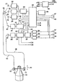
- the color detection sensor has two measuring heads 10, 11, the are arranged such that the optical output 12 of the measuring head 10, the optical input of the measuring head 11 is opposite.
- the object to be measured 13 for example a Bottle.
- the measuring heads 10, 11 are for example on one common bracket attached, which corresponds to the double arrow 14 is raised and lowered, wherein in the illustrated lowered position, the bottleneck in the beam path between the measuring head 10 and the measuring head 11 is located.
- the measuring head 10 is connected by means of a light guide 15 to a converging lens 16 connected sequentially with the light of three transmitters 17, 18, 19 is acted upon, for example are designed as light-emitting diodes.
- the light emitting diode 17 transmits red light, the light emitting diode 18 green light and the light emitting diode 19 blue light.
- the LEDs 17, 18, 19 are respectively Driver 20, 21, 22 upstream, which by means of a Multiplexer 24 pulse width modulated signals are supplied which are formed by a microprocessor 25.
- the measuring head 11 is connected by means of a light guide 26 to a Receiver 27 connected, in particular to a photodiode.
- the signals of the photodiode 27 are by means of a preamplifier 28 pre-amplified and forwarded to a signal conditioning 29.
- the signal conditioning 29 contains, for example two amplifier stages which can be selected by means of signal lines A, B a comb filter and a peakholder that peaks the received from the receiver 27 red, green and holding blue lights.
- the comb filter and the peakholder are generated by the microprocessor 25 control signals means Control lines 30, 31 supplied.
- the processed signals are supplied to a discriminator 32, which via control lines 33 receives control signals from the microprocessor 25.
- the discriminator 32 demultiplexing the received signals, has a sample-hold function, i. he stops each the last of the values. These values become voltage followers 34, 35, 36 output, thus the analog voltage values 37, 38, 39 corresponding to the red, green, blue Output light components received by the receiver 27 were.
- the analog voltage signal 37 at a red measured object 13 has a defined voltage value
- the analog signal 38 at a green DUT a defined Voltage value
- the analog signal 39 at a blue DUT 13 has a defined voltage value.
- These defined voltage values should on the one hand as possible be high to get a big signal swing, and then again also be balanced against each other.
- This calibration takes place when between the measuring heads 10, 11 a respect his color known reference object is arranged, for example a transparent DUT 13 or no DUT, so that the beam path between the measuring heads 10, 11 is not interrupted. In the embodiment may This can be done, for example, by placing them on a holder arranged measuring heads 10, 11 according to arrow 14 after be moved above.
- the light output becomes the transmitter 17, 18, 19 adjusted so that the defined Voltage signals 37, 38, 39 are present.
- This setting or better regulation takes place in that the voltage signals 37, 38, 39 are fed to the microprocessor 25, in which the nominal values of the voltage signals 37, 38, 39 For example, stored as a constant in a ROM.
- the microprocessor 25 are the setpoints with the actual values the voltage signals 37, 38, 39 compared. That of the Microprocessor 25 via the multiplexer 24 the drivers 20, 21, 22 pulse width modulated signal is for each the transmitter 17, 18, 19 changed until the voltage signals 37, 38, 39 correspond to the stored nominal values.
- the light output of the transmitter after calibration 17, 18, 19 is by means of another receiver 40, in particular a photodiode detected.
- the receiver 40 takes, for example from the converging lens 16 reflected light.
- the signal of the receiver 40 is by means of a preamplifier 41 pre-amplified and given to a signal conditioning 42.
- This signal conditioning 42 includes a means of a Control line 43 controlled by the microprocessor 25 comb filter and one by means of a control line 44 of the Microprocessor 25 controlled peakholder.
- This recycled Signals are stored in an erasable memory 46, especially in an EEPROM.
- the signals stored in the memory 46 are used to the transmitters 17, 18, 19 each to a constant light output regulate.
- the recipients continuously 40 received and processed signals to the microprocessor 25, which stores these with the memory 46 in the memory Comparing signals that serve as setpoints.
- the light emitter 17, 18 or 19 of the desired values is a Pulse width modulation until this deviation canceled is.
- the light output of the light emitter will be up to kept constant for the next calibration. If a calibration process causes the light output of one or several of the light emitter 17, 18 or 19 is changed, so the previously valid value in memory 46 is cleared and replaced by the new, received by the receiver 40 value.
- the calibration process described above is by means of a Start signal 47 is triggered and then runs fully automatically from.
- This calibration process is at initial startup the color detection sensor required so that it is appropriate is, the start signal 47 with the switching on of the power supply 48 trigger. In addition, it makes sense the To repeat the calibration process from time to time. For example can be provided that this pressed a start button which gives the calibration signal 47. With another Embodiment is provided that the start signal 47th with the help of a timer after a predetermined operating time is triggered. It is also possible the start signal 47 trigger in another way, for example by means of a limit switch, the raised position of the measuring heads 10, 11 monitored. This limit switch can be reached every time the raised position or after a predetermined number reaching the raised position a calibration process trigger.
- the amplification stages of the signal conditioning 29 can be selected are. This is done by means of a selection signal 48 for this gain selection entered into the microprocessor 25 is, then applied according to the signal lines A, B.
- the selection signal may be, for example, by the operator be given if it determines that DUT at the previously selected gain stage no produces sufficiently clear signal. It can then go on a much higher gain can be switched.
Landscapes
- Physics & Mathematics (AREA)
- Spectroscopy & Molecular Physics (AREA)
- General Physics & Mathematics (AREA)
- Spectrometry And Color Measurement (AREA)
Description
Claims (6)
- Dreibereichs-Verfahren zur analogen Farberkennung, bei welcher Lichtstrahlen von drei Lichtsendern (17, 18, 19) in jeweils einer Farbe auf ein zu erkennendes Objekt (13) gerichtet und die von dem Objekt kommenden Lichtstrahlen mittels eines Empfängers (27) aufgenommen werden, dessen Signale mittels einer Signalaufbereitung aufbereitet und als proportionale, analoge Spannungssignale (37, 38, 39) für jede der drei Farben ausgegeben werden, dadurch gekennzeichnet, dass ein automatisches Kalibrieren durchgeführt wird, bei welchem die Lichtleistung jedes Lichtsenders (17, 18, 19) mittels eines steuerbaren Reglers geregelt wird, der die während einer Referenzmessung gebildeten analogen Spannungssignale als Istwerte jeweils mit einem eingegebenen Sollwert vergleicht und bei Abweichungen der entsprechenden Istwerte von dem jeweiligen Sollwert die Lichtleistung des betreffenden Senders (17, 18, 19) nachführt, und dass die aufgrund des Kalibrierens eingestellten Lichtleistungen erfasst und abgespeichert werden und dassdanach durch Vergleichen der abgegebenen Lichtleistungen mit den abgespeicherten Werten eine Regelung zum Konstanthalten der Lichtleistung durchgeführt wird.
- Verfahren nach Anspruch 1, dadurch gekennzeichnet, dass das Kalibrieren mittels eines in den Regler eingebbaren Startsignals ausgelöst wird.
- Verfahren nach Anspruch 2, dadurch gekennzeichnet, dass das Startsignal nach Ablauf einer vorgebbaren Betriebszeit automatisch gebildet wird.
- Verfahren nach Anspruch 2, dadurch gekennzeichnet, dass das Startsignal mit dem Einschalten einer Stromversorgung automatisch gebildet wird.
- Dreibereichs-Farberkennungssensor, der drei auf ein zu erkennendes Objekt zu richtende Lichtsender (17, 18, 19) und einen die von dem Objekt kommenden Strahlen aufnehmenden Empfänger (27) aufweist, der an eine proportionale, analoge Spannungssignale (37, 38, 39) für jede der Farben ausgebende Auswerteeinrichtung angeschlossen ist, dadurch gekennzeichnet, dass für ein automatische Kalibrieren ein Regelkreis mit einem steuerbaren Regler vorgesehen ist, der Mittel zum Vergleichen von während einer Referenzmessung gemessenen Ist-Werten der analogen Spannungssignale (37, 38, 39) mit vorgegebenen Soll-Werten und, um die Ist-Werte der Spannungssignale auf die Soll-Werte einzuregeln, Mittel zum Nachführen der Lichtleistung der Sender (17, 18, 19) enthält, und dass ein weiterer Regelkreis zum Konstanthalten der Lichtleistungen der Sender (17, 18, 19) vorgesehen ist, der die beim Kalibrieren eingeregelten Lichtleistungen als Soll-Werte in einem Speicher (46) abspeichert und mit den Ist-Werten der Lichtleistungen vergleicht.
- Sensor nach Anspruch 5, dadurch gekennzeichnet, dass die Signalaufbereitung (29) wenigstens zwei unterschiedliche Verstärkungsstufen enthält, die mittels eines Auswahlsignals (48) auswählbar sind.
Applications Claiming Priority (2)
| Application Number | Priority Date | Filing Date | Title |
|---|---|---|---|
| DE19640671A DE19640671C1 (de) | 1996-10-02 | 1996-10-02 | Dreibereichs-Verfahren zur analogen Farberkennung und Vorrichtung zum Durchführen des Verfahrens |
| DE19640671 | 1996-10-02 |
Publications (3)
| Publication Number | Publication Date |
|---|---|
| EP0834726A2 EP0834726A2 (de) | 1998-04-08 |
| EP0834726A3 EP0834726A3 (de) | 1998-04-15 |
| EP0834726B1 true EP0834726B1 (de) | 2005-12-07 |
Family
ID=7807691
Family Applications (1)
| Application Number | Title | Priority Date | Filing Date |
|---|---|---|---|
| EP97116430A Expired - Lifetime EP0834726B1 (de) | 1996-10-02 | 1997-09-20 | Dreibereichs-Verfahren zur analogen Farberkennung und Vorrichtung zum Durchführen des Verfahrens |
Country Status (2)
| Country | Link |
|---|---|
| EP (1) | EP0834726B1 (de) |
| DE (2) | DE19640671C1 (de) |
Families Citing this family (4)
| Publication number | Priority date | Publication date | Assignee | Title |
|---|---|---|---|---|
| DE19852412B4 (de) * | 1998-11-13 | 2006-03-09 | Leuze Electronic Gmbh & Co Kg | Lichttaster |
| DE102007040873B4 (de) | 2007-08-29 | 2017-07-20 | Osram Gmbh | Beleuchtungsvorrichtung und Verfahren zur Anpassung einer Abstrahlcharakteristik einer Beleuchtungsvorrichtung |
| EP3236295B8 (de) * | 2016-04-19 | 2021-08-25 | Leuze electronic GmbH + Co KG | Lichtvorhang |
| EP4006507B1 (de) * | 2020-11-26 | 2025-06-11 | Ayxon-Dynamics GmbH | Optische vorrichtung für farbmesssysteme |
Family Cites Families (4)
| Publication number | Priority date | Publication date | Assignee | Title |
|---|---|---|---|---|
| DE3626373A1 (de) * | 1986-08-05 | 1988-02-18 | Fritz Kurandt | Vorrichtung zur schnellen farbmessung an unterschiedlichen proben |
| NL191070C (nl) * | 1987-06-25 | 1995-01-02 | Exploitatiemaatschappij H J Va | Inrichting voor het bepalen van de kleur van produkten, in het bijzonder tuinbouwprodukten. |
| US5229841A (en) * | 1991-07-10 | 1993-07-20 | Eaton Corporation | Color sensor employing optical fiber bundles with varied diameters |
| US5471052A (en) * | 1993-10-25 | 1995-11-28 | Eaton Corporation | Color sensor system using a secondary light receiver |
-
1996
- 1996-10-02 DE DE19640671A patent/DE19640671C1/de not_active Expired - Fee Related
-
1997
- 1997-09-20 DE DE59712508T patent/DE59712508D1/de not_active Expired - Fee Related
- 1997-09-20 EP EP97116430A patent/EP0834726B1/de not_active Expired - Lifetime
Also Published As
| Publication number | Publication date |
|---|---|
| DE19640671C1 (de) | 1998-05-07 |
| EP0834726A2 (de) | 1998-04-08 |
| DE59712508D1 (de) | 2006-01-12 |
| EP0834726A3 (de) | 1998-04-15 |
Similar Documents
| Publication | Publication Date | Title |
|---|---|---|
| EP2537598B1 (de) | Vorrichtung und Verfahren zur optischen Sortierung von Schüttgut | |
| DE3242219C1 (de) | Optisches Markenerkennungsgeraet | |
| DE19617009C2 (de) | Photoelektrische Meßeinrichtung | |
| DE19843151A1 (de) | Bearbeitungswerkzeug und Bearbeitungsvorrichtung zur Bearbeitung eines Werkstückes | |
| EP2409125B1 (de) | Verfahren und vorrichtung zur durchführung eines optischen vergleiches zwischen zumindest zwei mustern, vorzugsweise durch vergleich von auswählbaren ausschnitten | |
| DE2550891A1 (de) | Vorrichtung fuer die additive farbensynthese | |
| DE2838357C3 (de) | Vorrichtung zum automatischen Überprüfen von Knöpfen | |
| CH684833A5 (de) | Farbabstimmpult zur visuellen und messtechnischen Qualitätskontrolle von Druckbogen. | |
| EP2288463B1 (de) | Verfahren zum betrieb einer stichsäge. | |
| DE19640671C1 (de) | Dreibereichs-Verfahren zur analogen Farberkennung und Vorrichtung zum Durchführen des Verfahrens | |
| DE3434332A1 (de) | Vorrichtung zum erfassen der faerbung von sich bewegenden, flachgeformten koerpern | |
| DE2203194B2 (de) | Verfahren und Vorrichtung zum Steuern eines Gasschneidevorgangs | |
| DE3401475A1 (de) | Vorrichtung zur messung der farbe von gegenstaenden | |
| DE102014113070A1 (de) | Justiervorrichtung und Verfahren zum Ausrichten eines Bauteils an einem Fahrzeug | |
| DE10237426B4 (de) | Verfahren und Vorrichtung zum Vermessen von Werkzeugen | |
| EP0799419B1 (de) | Verfahren und vorrichtung zur kontinuierlichen messung der masse eines bewegten faserbandes | |
| DE3515608A1 (de) | Verfahren zur farbkompensation bei geraeten zum herstellen photographischer farbabzuege | |
| DE2729352C2 (de) | Vorrichtung zum Justieren eines photoelektronischen Fühlers | |
| DE19852412B4 (de) | Lichttaster | |
| DE3838820C2 (de) | ||
| DE2620838C3 (de) | Verfahren und Vorrichtung zur Einstellung eines günstigen Arbeitsbereichs für die Abtastung von optisch feststellbaren Markierungen auf einem Aufzeichnungsträger | |
| EP1136787B1 (de) | Objektabbildung mit Abstandskompensation ( Grösse, Farbe ) | |
| EP2955537B1 (de) | Vorrichtung und verfahren zur präsenzerkennung von einem mobilen gerät | |
| EP2353823B1 (de) | Positioniervorrichtung für verstellbare Elemente, Verfahren zum Positionieren von verstellbaren Elementen und Verwendung einer Positioniervorrichtung | |
| DE102022109910A1 (de) | Verfahren und Vorrichtung zur Sortierung von sich bewegenden Objekten |
Legal Events
| Date | Code | Title | Description |
|---|---|---|---|
| PUAI | Public reference made under article 153(3) epc to a published international application that has entered the european phase |
Free format text: ORIGINAL CODE: 0009012 |
|
| PUAL | Search report despatched |
Free format text: ORIGINAL CODE: 0009013 |
|
| AK | Designated contracting states |
Kind code of ref document: A2 Designated state(s): DE ES FR GB IT NL SE |
|
| AK | Designated contracting states |
Kind code of ref document: A3 Designated state(s): AT BE CH DE DK ES FI FR GB GR IE IT LI LU MC NL PT SE |
|
| 17P | Request for examination filed |
Effective date: 19980710 |
|
| AKX | Designation fees paid |
Free format text: DE ES FR GB IT NL SE |
|
| RBV | Designated contracting states (corrected) |
Designated state(s): DE ES FR GB IT NL SE |
|
| 17Q | First examination report despatched |
Effective date: 20030603 |
|
| GRAP | Despatch of communication of intention to grant a patent |
Free format text: ORIGINAL CODE: EPIDOSNIGR1 |
|
| GRAS | Grant fee paid |
Free format text: ORIGINAL CODE: EPIDOSNIGR3 |
|
| GRAA | (expected) grant |
Free format text: ORIGINAL CODE: 0009210 |
|
| AK | Designated contracting states |
Kind code of ref document: B1 Designated state(s): DE ES FR GB IT NL SE |
|
| PG25 | Lapsed in a contracting state [announced via postgrant information from national office to epo] |
Ref country code: IT Free format text: LAPSE BECAUSE OF FAILURE TO SUBMIT A TRANSLATION OF THE DESCRIPTION OR TO PAY THE FEE WITHIN THE PRESCRIBED TIME-LIMIT;WARNING: LAPSES OF ITALIAN PATENTS WITH EFFECTIVE DATE BEFORE 2007 MAY HAVE OCCURRED AT ANY TIME BEFORE 2007. THE CORRECT EFFECTIVE DATE MAY BE DIFFERENT FROM THE ONE RECORDED. Effective date: 20051207 |
|
| REG | Reference to a national code |
Ref country code: GB Ref legal event code: FG4D Free format text: NOT ENGLISH |
|
| REF | Corresponds to: |
Ref document number: 59712508 Country of ref document: DE Date of ref document: 20060112 Kind code of ref document: P |
|
| PG25 | Lapsed in a contracting state [announced via postgrant information from national office to epo] |
Ref country code: SE Free format text: LAPSE BECAUSE OF FAILURE TO SUBMIT A TRANSLATION OF THE DESCRIPTION OR TO PAY THE FEE WITHIN THE PRESCRIBED TIME-LIMIT Effective date: 20060307 |
|
| GBT | Gb: translation of ep patent filed (gb section 77(6)(a)/1977) |
Effective date: 20060222 |
|
| PG25 | Lapsed in a contracting state [announced via postgrant information from national office to epo] |
Ref country code: ES Free format text: LAPSE BECAUSE OF FAILURE TO SUBMIT A TRANSLATION OF THE DESCRIPTION OR TO PAY THE FEE WITHIN THE PRESCRIBED TIME-LIMIT Effective date: 20060318 |
|
| ET | Fr: translation filed | ||
| PLBE | No opposition filed within time limit |
Free format text: ORIGINAL CODE: 0009261 |
|
| STAA | Information on the status of an ep patent application or granted ep patent |
Free format text: STATUS: NO OPPOSITION FILED WITHIN TIME LIMIT |
|
| 26N | No opposition filed |
Effective date: 20060908 |
|
| PG25 | Lapsed in a contracting state [announced via postgrant information from national office to epo] |
Ref country code: NL Free format text: LAPSE BECAUSE OF NON-PAYMENT OF DUE FEES Effective date: 20070401 |
|
| PG25 | Lapsed in a contracting state [announced via postgrant information from national office to epo] |
Ref country code: DE Free format text: LAPSE BECAUSE OF NON-PAYMENT OF DUE FEES Effective date: 20070403 |
|
| GBPC | Gb: european patent ceased through non-payment of renewal fee |
Effective date: 20060920 |
|
| NLV4 | Nl: lapsed or anulled due to non-payment of the annual fee |
Effective date: 20070401 |
|
| REG | Reference to a national code |
Ref country code: FR Ref legal event code: ST Effective date: 20070531 |
|
| PG25 | Lapsed in a contracting state [announced via postgrant information from national office to epo] |
Ref country code: GB Free format text: LAPSE BECAUSE OF NON-PAYMENT OF DUE FEES Effective date: 20060920 |
|
| PG25 | Lapsed in a contracting state [announced via postgrant information from national office to epo] |
Ref country code: FR Free format text: LAPSE BECAUSE OF NON-PAYMENT OF DUE FEES Effective date: 20061002 |