EP0834702B1 - Wrasenabführung und Herd mit einer solchen Wrasenabführung - Google Patents
Wrasenabführung und Herd mit einer solchen Wrasenabführung Download PDFInfo
- Publication number
- EP0834702B1 EP0834702B1 EP97110169A EP97110169A EP0834702B1 EP 0834702 B1 EP0834702 B1 EP 0834702B1 EP 97110169 A EP97110169 A EP 97110169A EP 97110169 A EP97110169 A EP 97110169A EP 0834702 B1 EP0834702 B1 EP 0834702B1
- Authority
- EP
- European Patent Office
- Prior art keywords
- opening
- accordance
- fume tube
- frame
- removing fumes
- Prior art date
- Legal status (The legal status is an assumption and is not a legal conclusion. Google has not performed a legal analysis and makes no representation as to the accuracy of the status listed.)
- Expired - Lifetime
Links
- 239000003517 fume Substances 0.000 title claims 29
- 238000006073 displacement reaction Methods 0.000 claims description 22
- 229910052782 aluminium Inorganic materials 0.000 claims description 3
- XAGFODPZIPBFFR-UHFFFAOYSA-N aluminium Chemical compound [Al] XAGFODPZIPBFFR-UHFFFAOYSA-N 0.000 claims description 3
- 239000004411 aluminium Substances 0.000 claims 1
- 230000000284 resting effect Effects 0.000 claims 1
- 230000006641 stabilisation Effects 0.000 claims 1
- 229910052751 metal Inorganic materials 0.000 description 5
- 239000002184 metal Substances 0.000 description 5
- 230000000087 stabilizing effect Effects 0.000 description 3
- 238000005452 bending Methods 0.000 description 2
- 238000011161 development Methods 0.000 description 2
- 230000018109 developmental process Effects 0.000 description 2
- 238000004049 embossing Methods 0.000 description 2
- 230000005494 condensation Effects 0.000 description 1
- 238000009833 condensation Methods 0.000 description 1
- 238000001816 cooling Methods 0.000 description 1
- 230000001419 dependent effect Effects 0.000 description 1
- 238000003780 insertion Methods 0.000 description 1
- 230000037431 insertion Effects 0.000 description 1
- 238000009434 installation Methods 0.000 description 1
- 239000000463 material Substances 0.000 description 1
- 238000004080 punching Methods 0.000 description 1
- 229910001220 stainless steel Inorganic materials 0.000 description 1
- 239000010935 stainless steel Substances 0.000 description 1
Images


Classifications
-
- F—MECHANICAL ENGINEERING; LIGHTING; HEATING; WEAPONS; BLASTING
- F24—HEATING; RANGES; VENTILATING
- F24C—DOMESTIC STOVES OR RANGES ; DETAILS OF DOMESTIC STOVES OR RANGES, OF GENERAL APPLICATION
- F24C15/00—Details
- F24C15/20—Removing cooking fumes
- F24C15/2042—Devices for removing cooking fumes structurally associated with a cooking range e.g. downdraft
Definitions
- the invention relates to a vapor discharge for removing vapors from an oven muffle and a stove with such a vapor discharge.
- DE-OS 33 38 094 describes a baking and roasting oven with a device for removal of vapors known to have a vapor hose at one end the exit opening of an oven muffle and at its other end with an air shaft for cooling air is firmly connected.
- the air chute opens into an outlet opening for the vapor, which is located on the side wall of the furnace.
- the mentioned literature deals with the problem of condensation from the Drain the vapor hose to a suitable location in the oven.
- vapors are also known with a stainless steel vapor pipe, the first end of which is connected to a connecting piece on the furnace muffle and the second end of which is connected to a vapor outlet opening.
- the vapor outlet opening can in particular be provided in or on a hob assigned to the stove.
- the invention is therefore based on the object, a vapor evacuation for removal of vapors from an oven muffle that can be easily assembled.
- the vapor hose is displaceable in the holding device and is also flexible, the also different dimensional tolerances during installation the oven muffle or a stove adapted with an oven muffle become. This significantly reduces the assembly effort.
- the Holding device a frame and a displaceable in the frame Sliding element with an opening for insertion the second end of the vapor hose.
- the frame can now preferably be two essentially parallel running guide rails on different sides have the opening of the displacement element.
- the sliding element then has at least two guide elements, wherein at least one guide element along each a guide rail of the frame is feasible.
- the sliding element can also on the of the guide elements opposite side on opposite sides each of the opening slidably rests on the frame Have stabilizing element.
- the opening on the sliding element is preferably in one first direction as wide as the cross section of the vapor hose and expanded even more in a second direction, so that the vapor hose in this second direction is slidable in the opening.
- This second direction, along which the vapor hose goes in the opening is displaceable, is preferably substantially orthogonal to the direction of displacement of the displacement element as part of. As a result, the vapor hose is in all movable in three spatial directions.
- the holding device has at the second end of the vapor hose fastened fastener with at least two support elements protruding outwards from the vapor hose to support the vapor hose on the edge of the opening of the sliding element.
- the fastening element at least four support elements, wherein each at least two support elements at a distance of at least two other support elements along a longitudinal direction of the vapor hose are staggered and this distance is about the depth of the opening or the width corresponds to the edge of this opening in the displacement element. This can be done by inserting and then turning the Vapor hose a secure attachment of the vapor hose can be reached on the sliding element.
- the stove includes an oven muffle and a vapor guide according to of the invention, the first end of the vapor hose is connected to the oven muffle.
- the stove has a Muffle cover plate with which the frame for the sliding element is formed.
- An advantageous embodiment of the stove stands out characterized in that a vapor outlet opening and a connector for connecting the second end of the vapor hose are provided with the vapor outlet opening.
- the vapor outlet opening is preferably at or in one Cooktop arranged.
- the stove and possibly the hob are preferred Built-in appliances.
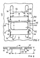
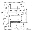
- 1 to 3 is a holding device designated 4 illustrated for a vapor hose, not shown.
- a frame with 40 a sliding element with 41, an opening in the sliding element 41 with 42, four guide elements on the displacement element 41 with 60 to 63, two stabilizing elements on the sliding element 41 with 64 and 65, embossing on the sliding element 41 with 66 designated, two guide rails on the frame 40 with 50 and 51, four guide slots frame 40 with 70 to 73, two stops on frame 40 with 75 and 76 and a top of the Frame 40 with 30 and one facing away from the top 30 Underside of the frame 40 designated 31.
- the frame 40 has a substantially rectangular recess 32, which are on the long sides outside in each two guide slots 70 and 71 and 72 and 73 continues.
- the two guide slots 71 and 72 are from the stop 76 separated and the second guide slots 72 and 73 from the stop 75. Both stops 75 and 76 are sufficient to the recess 32.
- the by the distance between the two stops 75 and 76 defined expansion of the recess 32 in the longitudinal direction is designated A.
- the frame 40 On the underside 31 of the frame 40 are on opposite Sides of the recess 32 lying and in the longitudinal direction extending guide rails 50 and 51 formed, the straight on the edge of the guide slots 70 and 72 or Continue 71 and 73. If the frame 40 is made of a sheet metal exists, this can be done by bending the edge of the recess 32 including the guide slots 70 to 73 from the top 30 of the frame 40 to the bottom 31 happen.
- a displacement element 41 is fitted into the recess 32 and used that in the longitudinal direction of the recess 32 along an axis in the two illustrated by two arrows Directions is displaceable.
- the sliding element 41 has two guide elements 60 and on each side 63 or 61 and 62 on that on an associated guide rail 50 or 51 of the frame 40 can slide along.
- the guide elements 60 and 63 on the Guide rail 50 and the guide elements 61 and 62 of the guide rail 51 have the guide elements 60 to 63 on the side of the guide rails facing away from the recess 32 50 and 51 each to the bottom 31 of the frame 40 out. If the sliding part 41 made of a metal sheet there is, for example, by deformation by bending the sheet.
- An opening 42 is provided in the displacement element 41 for example, is at least approximately rectangular in shape and, measured in the longitudinal direction of the recess 32 of the frame 40, has a smaller dimension (width) b than a length B orthogonal thereto is preferred the length B of the opening 42 in the sliding part 41 practically as large as the width of the recess 32 in the frame 40.
- Die Width b of the opening 42 is at least as large as that Diameter with a circular cross section or in general the clear width of the cross section of the not shown Steam hose, so the steam hose through the opening 42 can be pushed through.
- the Width b is about the same size as the clear width of the cross-section of the vapor hose so that the vapor hose is on abuts the edge of the opening 42.
- This edge of the opening 42 preferably sits completely or at least partially towards-from the top 30 to the bottom 31 of the frame 40 downwards in extensions 67 and 68. These extensions 67 and 68 strike when shifted of the displacement element 41 in the recess 32 in one end position each on the assigned stops 75 or 76 of the frame 40.
- the maximum shift distance the displacement element 41 is thus equal to A-b.
- the displacement element 41 can, however, also be dimensioned in this way be that the guide elements 60 to 63 at the ends of the assigned guide slots 70 to 73 and thus define the end position of the displacement element 41.
- the vapor hose can thus be connected to the displacement element 41 back and forth in the direction of displacement by the distance A-b be moved. Furthermore, the vapor hose can also be used in the Opening 42 perpendicular to the direction of displacement of the displacement element 41 be moved back and forth.
- the maximal Displacement distance for this degree of freedom of movement is equal to the length b of the opening 42 minus the diameter the vapor hose, but at least B-b.
- the vapor hose can practically be in any position within the recess 32 are brought into the frame 40. Thereby can laterally, i.e. extending parallel to the frame 40 Dimensional tolerances for the assembly of the vapor hose compensated become. This compensation of dimensional tolerances can expected dimensional tolerances by dimensioning the Dimensions A and B can be adjusted.
- the frictional force of the displaced displacement element 41 on the frame 40 is chosen larger than the restoring force through the stretched vapor hose so that the sliding element 41 also remains in a set position.
- the embossments 66 in the Sliding element 41 is provided, which against the frame 40th to press.
- FIGS. 4 and 5 show two side views, rotated 90 degrees relative to one another, of a vapor hose 3 provided with a fastening element 43.
- the fastening element 43 is provided at a second end 31 of the vapor hose 3 and surrounds it Vapor hose 3 in the form of a sleeve or clamp, preferably made of a bendable metal sheet.
- two supporting elements 44 and 45 or 46 and 48 and 49 or 49 and 49 project outward from the vapor hose 4 on opposite sides of the same height, seen in the longitudinal direction of the vapor hose 4.
- the distances between support elements 44 and 46, 46 and 48, 45 and 47 and 47 and 49 lying one above the other are all the same and are designated by d.
- This common distance d corresponds approximately to the depth of the opening 42 in the displacement element 41 of the holding device 4 according to FIGS. 1 to 3, which depth is essentially determined by the length of the extensions 67 and 68 and the thickness of the displacement part 41.
- the vapor hose 4 can now have its second end 31 be securely attached to the slide member 41 by the vapor hose 3 with the fastener 43 such is inserted into the opening 42 that the support elements 44 to 49 show in the longitudinal direction of the opening 42, and then is rotated by 90 degrees so that four of the support elements 44 to 49 on the two opposite edges the opening 42 at the top and bottom of the sliding element 41 are supported.
- the distance by which second end 31 of the vapor hose 3 from the displacement element 41 protrudes upwards.
- the support elements 44 to 48 can in particular by partially punching out of holes in the metal sheet of the fastener 43 and folding up the punched-out parts to the outside getting produced.
- the fastening element 43 also has two stops 52 to 53, which are 90 degrees to the support elements 44 to 49 are staggered. These stops 52 and 53 offer a protection against that the vapor hose 3 through too far the opening 42 is pulled through and is thereby destroyed.
- the fastening element 43 can be in two parts or also in one part be trained.
- the vapor hose 4 consists of a flexible material and is preferably a flexible hose or tube Aluminum, which is available on the market in a manner known per se is, for example from Westaflex.
- FIG. 6 now shows an overall view of a vapor discharge for removing vapors W from a muffle 2 one Cooker.
- the flexible vapor hose 3 is with its first End 30 using a clamp 10 on a muffle socket 20 of the oven muffle 2 attached.
- With its second end 31 is the vapor hose 3 again with the help of a fastener 43 attached to a sliding element 41, that is slidable in the frame 40.
- the fastening element 43 has only four Support elements 44 to 47.
- the fastener 43 can of course also have more support elements to a variable distance between the second end. 31 of the vapor hose 3 to be able to adjust upwards.
- the frame 40 is preferably part of a muffle cover plate 6 which is preferably formed from sheet metal and the furnace muffle 2 separates from an overlying hob 9.
- a muffle cover plate 6 which is preferably formed from sheet metal and the furnace muffle 2 separates from an overlying hob 9.
- On the edge of the Hob 9 or in hob 9 itself is at least one Vapor outlet opening 7 provided with the second End 31 of the vapor hose 3 connected via a connector 8 is.
- the connector 8 can, for example Plastic exist and is in the vapor hose 3 inserted its second end 31. At the hob 9 the connector 8 inserted or clipped.
- assemble the vapor discharge preferably first the connector 8 at the vapor outlet opening 7 and the hob 9 attached and then the flexible vapor hose 3 via the sliding holding device 4 moved until the second end 31 comes to lie directly under the connector 8. Then the second end 31 of the vapor hose 3 is inserted the fastener 43 through the opening 42 of the displacement element 41 over the connecting piece of the connector 8 pushed. You get a gas-tight and easy to. assembling vapor discharge.
Landscapes
- Engineering & Computer Science (AREA)
- Chemical & Material Sciences (AREA)
- Combustion & Propulsion (AREA)
- Mechanical Engineering (AREA)
- General Engineering & Computer Science (AREA)
- Muffle Furnaces And Rotary Kilns (AREA)
- Baking, Grill, Roasting (AREA)
- Electrical Discharge Machining, Electrochemical Machining, And Combined Machining (AREA)
Description
- FIG 1
- eine Ausführungsform einer Haltevorrichtung für einen Wrasenschlauch in einer Draufsicht von oben,
- FIG 2
- eine Draufsicht auf diese Haltevorrichtung von unten,
- FIG 3
- eine Längsansicht dieser Haltevorrichtung,
- FIG 4
- ein Befestigungselement am Wrasenschlauch in einer Seitenansicht,
- FIG 5
- das Befestigungselement der FIG 5 in einer um 90 Grad gedrehten Seitenansicht und
- FIG 6
- eine Gesamtansicht einer Wrasenabführung.
Wrasenschlauch 3 in Form einer Hülse oder Schelle, vorzugsweise aus einem biegbaren Metallblech. Am Befestigungselement 43 ragen nun an gegenüberliegenden Seiten jeweils zwei auf, in Längsrichtung des Wrasenschlauchs 4 gesehen, gleicher Höhe befindliche Stützelemente 44 und 45 bzw. 46 und 48 bzw. 49 und 49 nach außen von dem Wrasenschlauch 4 weg. Die Abstände zwischen jeweils übereinanderliegenden Stütelementen 44 und 46, 46 und 48, 45 und 47 und 47 und 49 sind alle gleich und mit d bezeichnet. Dieser gemeinsame Abstand d entspricht etwa der im wesentlichen durch die Länge der Fortsätze 67 und 68 und die Dicke des Verschiebeteils 41 bestimmten Tiefe der Öffnung 42 im Verschiebeelement 41 der Haltevorrichtung 4 gemäß den FIG 1 bis 3.
- 2
- Ofenmuffel
- 3
- Wrasenschlauch
- 4
- Haltevorrichtung
- 6
- Muffelabdeckplatte
- 7
- Wrasenaustrittsöffnung
- 8
- Anschlußstück
- 9
- Kochfeld
- 10
- Schelle
- 20
- Muffelstutzen
- 30
- Oberseite
- 31
- Unterseite
- 32
- Aussparung
- 40
- Rahmen
- 41
- Verschiebeelement
- 42
- Öffnung
- 43
- Befestigungselement
- 44 bis 49
- Stützelement
- 50,51
- Führungsschiene
- 52,53
- Anschläge
- 60 bis 63
- Führungselement
- 64,65
- Stabilisierungselement
- 66
- Prägung
- 67, 68
- Fortsatz
- 70,71,72,73
- Führungsschlitz
- 75,76
- Anschlag
- d
- Abstand
- b
- Breite
- 1
- Länge
- A
- Verschiebestrecke
Claims (14)
- Wrasenabführung zum Abführen von Wrasen aus einer Ofenmuffel (2) mita) einem flexiblen Wrasenschlauch (3), der mit, einem ersten Ende (30) an die Ofenmuffel (2) anschließbar ist, undb) einer ortsfesten Haltevorrichtung (4) zum Halten des Wrasenschlauchs (3) an seinem zweiten Ende (31) derart, daß der Wrasenschlauch (3) an seinem zweiten Ende (31) in der ortsfesten Haltevorrichtung in wenigstens einer vorgegebenen Richtung verschiebbar ist.
- Wrasenabführung nach Anspruch 1, bei der der Wrasenschlauch (3) aus Aluminium besteht.
- Wrasenabführung nach Anspruch 1 oder Anspruch 2, bei der die Haltevorrichtung (4) einen Rahmen (40) und ein in dem Rahmen (4) verschiebbares Verschiebeelement (41) mit einer Öffnung (42) zur Aufnahme des zweiten Endes (31) des Wrasenschlauches (3) umfaßt.
- Wrasenabführung nach Anspruch 3, bei der der Rahmen (40) zwei im wesentlichen parallel verlaufende Führungsschienen (50,51) auf verschiedenen Seiten der Öffnung (42) des Verschiebeelements (41) umfaßt und das Verschiebeelement (41) wenigstens zwei Führungselemente (60,61,62,63) aufweist, wobei jeweils wenigstens ein Führungselement (60 bis 62) entlang jeweils einer Führungsschiene (50,51) führbar ist.
- Wrasenabführung nach Anspruch 4, bei der das Verschiebeelement (41) auf der von den Führungselementen (60 bis 63) abgewandten Seite auf gegenüberliegenden Seiten der Öffnung (42) jeweils ein auf dem Rahmen (40) verschiebbar aufliegendes Stabilisierungselement (64,65) aufweist.
- Wrasenabführung nach einem der Ansprüche 3 bis 5, bei der die Öffnung (42) in einer ersten Richtung so breit wie der Querschnitt des Wrasenschlauches (3) ist und in einer zweiten Richtung stärker ausgedehnt ist, so daß der Wrasenschlauch (3) in dieser zweiten Richtung in der Öffnung (42) verschiebbar ist.
- Wrasenabführung nach Anspruch 6, bei der die zweite Richtung, entlang der der Wrasenschlauch (3) in der Öffnung (42) verschiebbar ist, im wesentlichen orthogonal zur Verschieberichtung des Verschiebeelements (41) im Rahmen (40) verläuft.
- Wrasenabführung nach einem der Ansprüche 3 bis 7, bei der die Haltevorrichtung (4) ferner ein am zweiten Ende (31) des Wrasenschlauchs (3) befestigtes Befestigungselement (43) mit wenigstens zwei vom Wrasenschlauch (3) nach außen abstehenden Stützelementen (44,45) zum Abstützen des Wrasenschlauchs (3) auf dem Rand der Öffnung (42) des Verschiebeelements (41) umfaßt.
- Wrasenabführung nach Anspruch 8, bei der das Befestigungselement (43) wenigstens vier Stützelemente (44 bis 47) aufweist, wobei jeweils wenigstens zwei Stützelemente (44,45) in einem Abstand von wenigstens zwei anderen Stützelementen (46,47) entlang einer Längsrichtung des Wrasenschlauchs (3) versetzt angeordnet sind und dieser Abstand etwa der Tiefe der Öffnung (42) im Verschiebeelement (41) entspricht.
- Herd mita) einer Ofenmuffel (2) undb) einer Wrasenabführung nach einem der vorhergehenden Ansprüche,c) wobei das erste Ende (3) des Wrasenschlauchs (3) an die Ofenmuffel (2) angeschlossen ist.
- Herd nach Anspruch 10 mit einer Wrasenabführung nach einem der Ansprüche 3 bis 9 und mit einer Muffelabdeckplatte (6), in der der Rahmen (40) für das Verschiebeelement (41) gebildet ist.
- Herd nach Anspruch 10 oder Anspruch 11 mit einer Wrasenaustrittsöffnung (7) und einem Anschlußstück (8) zum Verbinden des zweiten Endes (31) des Wrasenschlauches (3) mit der Wrasenaustrittsöffnung (7).
- Herd nach Anspruch 12 mit einem Kochfeld (9), wobei die Wrasenaustrittsöffnung (7) am oder im Kochfeld (9) angeordnet ist.
- Herd nach einem der Ansprüche 10 bis 13, ausgebildet als Einbauherd.
Applications Claiming Priority (2)
| Application Number | Priority Date | Filing Date | Title |
|---|---|---|---|
| DE29617057U DE29617057U1 (de) | 1996-10-02 | 1996-10-02 | Wrasenabführung und Herd mit einer solchen Wrasenabführung |
| DE29617057U | 1996-10-02 |
Publications (2)
| Publication Number | Publication Date |
|---|---|
| EP0834702A1 EP0834702A1 (de) | 1998-04-08 |
| EP0834702B1 true EP0834702B1 (de) | 2001-10-24 |
Family
ID=8029981
Family Applications (1)
| Application Number | Title | Priority Date | Filing Date |
|---|---|---|---|
| EP97110169A Expired - Lifetime EP0834702B1 (de) | 1996-10-02 | 1997-06-21 | Wrasenabführung und Herd mit einer solchen Wrasenabführung |
Country Status (2)
| Country | Link |
|---|---|
| EP (1) | EP0834702B1 (de) |
| DE (2) | DE29617057U1 (de) |
Cited By (2)
| Publication number | Priority date | Publication date | Assignee | Title |
|---|---|---|---|---|
| EP2372254A1 (de) | 2010-03-30 | 2011-10-05 | Electrolux Home Products Corporation N.V. | Einheit zur Montage eines Belüftungskanals in einer Gehäusewand eines Haushaltsgeräts und Herds, das eine solche Einheit umfasst |
| EP2474787B1 (de) | 2012-04-13 | 2016-10-12 | V-Zug AG | Dampfgargerät |
Families Citing this family (2)
| Publication number | Priority date | Publication date | Assignee | Title |
|---|---|---|---|---|
| DE102004050614A1 (de) * | 2004-10-18 | 2006-04-20 | BSH Bosch und Siemens Hausgeräte GmbH | Hausgeräteführungsvorrichtung |
| DE102010017126A1 (de) | 2010-05-28 | 2011-12-01 | Miele & Cie. Kg | Gargerät |
Family Cites Families (4)
| Publication number | Priority date | Publication date | Assignee | Title |
|---|---|---|---|---|
| DE3004225C2 (de) * | 1980-02-06 | 1981-12-03 | G. Bauknecht Gmbh, 7000 Stuttgart | Dunstabzugshaube für Abluftbetrieb mit einer schlauchartigen Luftleitvorrichtung |
| DE3225953A1 (de) * | 1982-07-10 | 1984-01-12 | Schmidt, Kranz & Co GmbH Zweigniederlassung Zorge, 3421 Zorge | Absaugarm zum absaugen von rauch und gasen |
| DE3338094A1 (de) * | 1983-10-20 | 1985-05-02 | Licentia Patent-Verwaltungs-Gmbh, 6000 Frankfurt | Back- und bratofen mit einer wrasenabfuehrungseinrichtung |
| IT235885Y1 (it) * | 1995-06-27 | 2000-07-18 | Coral Spa | Condotto universale di collegamento tra un aspiratore ed un elementodi convogliamento dei fumi in posti di lavorazioni industriali. |
-
1996
- 1996-10-02 DE DE29617057U patent/DE29617057U1/de not_active Expired - Lifetime
-
1997
- 1997-06-21 DE DE59705059T patent/DE59705059D1/de not_active Expired - Fee Related
- 1997-06-21 EP EP97110169A patent/EP0834702B1/de not_active Expired - Lifetime
Cited By (2)
| Publication number | Priority date | Publication date | Assignee | Title |
|---|---|---|---|---|
| EP2372254A1 (de) | 2010-03-30 | 2011-10-05 | Electrolux Home Products Corporation N.V. | Einheit zur Montage eines Belüftungskanals in einer Gehäusewand eines Haushaltsgeräts und Herds, das eine solche Einheit umfasst |
| EP2474787B1 (de) | 2012-04-13 | 2016-10-12 | V-Zug AG | Dampfgargerät |
Also Published As
| Publication number | Publication date |
|---|---|
| DE59705059D1 (de) | 2001-11-29 |
| EP0834702A1 (de) | 1998-04-08 |
| DE29617057U1 (de) | 1998-02-05 |
Similar Documents
| Publication | Publication Date | Title |
|---|---|---|
| EP1383967B1 (de) | Abdeckung für eine entwässerungseinrichtung | |
| EP1158185A2 (de) | Schnellbefestigungselement | |
| EP3773075B1 (de) | Vorrichtung zum fixieren eines schubelementes und verfahren zur montage und demontage eines schubelementes | |
| EP3713448B1 (de) | Vorrichtung zum festlegen eines schubelementes und möbel | |
| EP4145003A1 (de) | Vorrichtung zur verbindung von möbelteilen und verfahren zur montage eines möbels | |
| DE20010037U1 (de) | Schnellbefestigungselement | |
| DE19944642A1 (de) | Befestigungsvorrichtung | |
| EP3585210B1 (de) | Schubkasten und verfahren zur montage eines schubkastens | |
| DE112019007932T5 (de) | Positioniereinheit für Nutensteine | |
| DE102016103169B4 (de) | Adapter zur Fixierung eines Bodens an einer Seitenzarge, Schubkasten und Verfahren zur Montage eines Bodens an einem Adapter | |
| EP2642896B1 (de) | Behältnisschiene für einen schubladenbehälter | |
| EP4007096B1 (de) | An einer begrenzungsfläche eines gebäudes festlegbares kabelrinnensystem | |
| EP3071896B1 (de) | Haltevorrichtung für ein gehäuse und verfahren zur montage des gehäuses unter verwendung der haltevorrichtung | |
| EP0834702A1 (de) | Wrasenabführung und Herd mit einer solchen Wrasenabführung | |
| DE29614724U1 (de) | Wandkonsole für Heizkörper | |
| WO2020058000A1 (de) | Schubkasten und einheit aus einer auszugsführung und einem schubkasten | |
| WO1994021970A1 (de) | Standkonsole für heizkörper | |
| EP4536508B1 (de) | Dachhaltegriff für fahrzeuge | |
| DE102004059815B4 (de) | Montageträger für Unterflurdose | |
| EP0901760B1 (de) | Auszugschiene und Ausziehtisch mit einer solchen Auszugschiene | |
| BE1031455B1 (de) | Halterahmen für einen Steckverbinder | |
| DE102010016434B4 (de) | Clip zur Befestigung einer Leiste an einem Trägerteil, insbesondere an einem Kraftfahrzeug | |
| DE102023117769A1 (de) | Führungsvorrichtung | |
| DE3606502C1 (en) | Device for connecting cable channels which abut flush against one another | |
| DE102023130065A1 (de) | Auszugsführung und Verfahren zur Montage einer Auszugsführung |
Legal Events
| Date | Code | Title | Description |
|---|---|---|---|
| PUAI | Public reference made under article 153(3) epc to a published international application that has entered the european phase |
Free format text: ORIGINAL CODE: 0009012 |
|
| 17P | Request for examination filed |
Effective date: 19980126 |
|
| AK | Designated contracting states |
Kind code of ref document: A1 Designated state(s): CH DE FR GB IT LI |
|
| AKX | Designation fees paid |
Free format text: CH DE FR GB IT LI |
|
| RBV | Designated contracting states (corrected) |
Designated state(s): CH DE FR GB IT LI |
|
| 17Q | First examination report despatched |
Effective date: 20000707 |
|
| GRAG | Despatch of communication of intention to grant |
Free format text: ORIGINAL CODE: EPIDOS AGRA |
|
| GRAG | Despatch of communication of intention to grant |
Free format text: ORIGINAL CODE: EPIDOS AGRA |
|
| GRAH | Despatch of communication of intention to grant a patent |
Free format text: ORIGINAL CODE: EPIDOS IGRA |
|
| GRAH | Despatch of communication of intention to grant a patent |
Free format text: ORIGINAL CODE: EPIDOS IGRA |
|
| GRAA | (expected) grant |
Free format text: ORIGINAL CODE: 0009210 |
|
| AK | Designated contracting states |
Kind code of ref document: B1 Designated state(s): CH DE FR GB IT LI |
|
| REG | Reference to a national code |
Ref country code: CH Ref legal event code: NV Representative=s name: TROESCH SCHEIDEGGER WERNER AG Ref country code: CH Ref legal event code: EP |
|
| REF | Corresponds to: |
Ref document number: 59705059 Country of ref document: DE Date of ref document: 20011129 |
|
| REG | Reference to a national code |
Ref country code: GB Ref legal event code: IF02 |
|
| GBT | Gb: translation of ep patent filed (gb section 77(6)(a)/1977) |
Effective date: 20020106 |
|
| ET | Fr: translation filed | ||
| PLBE | No opposition filed within time limit |
Free format text: ORIGINAL CODE: 0009261 |
|
| STAA | Information on the status of an ep patent application or granted ep patent |
Free format text: STATUS: NO OPPOSITION FILED WITHIN TIME LIMIT |
|
| 26N | No opposition filed | ||
| PGFP | Annual fee paid to national office [announced via postgrant information from national office to epo] |
Ref country code: GB Payment date: 20040528 Year of fee payment: 8 |
|
| PGFP | Annual fee paid to national office [announced via postgrant information from national office to epo] |
Ref country code: FR Payment date: 20040618 Year of fee payment: 8 |
|
| PG25 | Lapsed in a contracting state [announced via postgrant information from national office to epo] |
Ref country code: GB Free format text: LAPSE BECAUSE OF NON-PAYMENT OF DUE FEES Effective date: 20050621 |
|
| PGFP | Annual fee paid to national office [announced via postgrant information from national office to epo] |
Ref country code: CH Payment date: 20050622 Year of fee payment: 9 |
|
| PG25 | Lapsed in a contracting state [announced via postgrant information from national office to epo] |
Ref country code: FR Free format text: LAPSE BECAUSE OF NON-PAYMENT OF DUE FEES Effective date: 20060228 |
|
| GBPC | Gb: european patent ceased through non-payment of renewal fee |
Effective date: 20050621 |
|
| REG | Reference to a national code |
Ref country code: FR Ref legal event code: ST Effective date: 20060228 |
|
| PG25 | Lapsed in a contracting state [announced via postgrant information from national office to epo] |
Ref country code: LI Free format text: LAPSE BECAUSE OF NON-PAYMENT OF DUE FEES Effective date: 20060630 Ref country code: CH Free format text: LAPSE BECAUSE OF NON-PAYMENT OF DUE FEES Effective date: 20060630 |
|
| REG | Reference to a national code |
Ref country code: CH Ref legal event code: PL |
|
| PGFP | Annual fee paid to national office [announced via postgrant information from national office to epo] |
Ref country code: IT Payment date: 20090619 Year of fee payment: 13 |
|
| PGFP | Annual fee paid to national office [announced via postgrant information from national office to epo] |
Ref country code: DE Payment date: 20090625 Year of fee payment: 13 |
|
| PG25 | Lapsed in a contracting state [announced via postgrant information from national office to epo] |
Ref country code: IT Free format text: LAPSE BECAUSE OF NON-PAYMENT OF DUE FEES Effective date: 20100621 |
|
| PG25 | Lapsed in a contracting state [announced via postgrant information from national office to epo] |
Ref country code: DE Free format text: LAPSE BECAUSE OF NON-PAYMENT OF DUE FEES Effective date: 20110101 |