EP0834701A1 - Baking oven with internally ventilated door seal - Google Patents
Baking oven with internally ventilated door seal Download PDFInfo
- Publication number
- EP0834701A1 EP0834701A1 EP97115980A EP97115980A EP0834701A1 EP 0834701 A1 EP0834701 A1 EP 0834701A1 EP 97115980 A EP97115980 A EP 97115980A EP 97115980 A EP97115980 A EP 97115980A EP 0834701 A1 EP0834701 A1 EP 0834701A1
- Authority
- EP
- European Patent Office
- Prior art keywords
- door seal
- air
- oven
- door
- seal
- Prior art date
- Legal status (The legal status is an assumption and is not a legal conclusion. Google has not performed a legal analysis and makes no representation as to the accuracy of the status listed.)
- Granted
Links
Images

Classifications
-
- F—MECHANICAL ENGINEERING; LIGHTING; HEATING; WEAPONS; BLASTING
- F24—HEATING; RANGES; VENTILATING
- F24C—DOMESTIC STOVES OR RANGES ; DETAILS OF DOMESTIC STOVES OR RANGES, OF GENERAL APPLICATION
- F24C15/00—Details
- F24C15/006—Arrangements for circulation of cooling air
-
- F—MECHANICAL ENGINEERING; LIGHTING; HEATING; WEAPONS; BLASTING
- F24—HEATING; RANGES; VENTILATING
- F24C—DOMESTIC STOVES OR RANGES ; DETAILS OF DOMESTIC STOVES OR RANGES, OF GENERAL APPLICATION
- F24C15/00—Details
- F24C15/02—Doors specially adapted for stoves or ranges
- F24C15/021—Doors specially adapted for stoves or ranges sealings for doors or transparent panel
Definitions
- the invention relates to an oven with an oven muffle, one oven door and one between the oven door and the front of the oven muffle arranged door seal.
- Door seals for ovens that lock the oven door against the Sealing the front of the oven muffle are in many Embodiments known. You are at the front of the Oven muffle or attached to the oven door and either as angled, laterally open silicone hoses or designed as metal mesh strands.
- silicone seals also for pyrolysis devices were used, this was with a significant design effort connected to the front of the device to be designed so that sufficient in the area of the seal low temperatures prevail, i.e. that of silicone seals maximum tolerable limit temperatures of Do not exceed 250 to 270 ° C.
- pyrolysis devices are currently mostly used metal mesh seals filled with glass mesh are used, that during pyrolytic self-cleaning withstand the very high operating temperatures. Due to the high thermal expansion of this type of seal however, when attaching the seal Special arrangements are made to ensure satisfactory To ensure sealing. Also are these seals are heavy in their porous surface structure cleaned and hardened grease with time, which reduces the sealing effect. About that assembly is also difficult.
- the invention lies in consideration of the above State of the art based on the technical problem, an oven with improved door seal, in particular for pyrolysis devices or other ovens with very high To create operating temperatures.
- This problem is in an oven of the type described Art solved in that he has a door seal ventilation system for cooling the door seal with in your Air flowing inside.
- the door seal as a hollow profile with a continuous interior formed and has an air inlet opening and Air outlet opening.
- a door seal air duct with a blower is provided in the area of the air inlet opening the door seal has a higher air pressure than in the area of the air outlet opening of the door seal generate so that cooling air due to the air pressure difference positively guided through the interior of the door seal flows.
- Components of the invention are thus a hollow profile trained door seal and a coordinated Air routing, which is generally called a door seal ventilation system can designate.
- a door seal ventilation system By the inside of the hollow profile flowing air can act on the door seal Temperatures even at higher operating temperatures of the oven are kept so low that the maximum compatible with the respective sealing material Temperatures are not exceeded. This makes one weakening of material due to high temperatures counteracted and thus the life of the door seal elevated. It is also possible to use materials with a lot good sealing properties, but relatively low maximum tolerable temperatures as standard in ovens to use.
- the door seal designed as a hollow profile is preferably closed on the side.
- the door seal For the function of the door seal, it is sufficient if it has one only air inlet opening to enter through the Door seal air duct generated and to the air inlet opening guided cooling air and a single air outlet to exit through the door seal has flowed cooling air.
- the door seal also has several air inlet openings and / or include air outlet openings can. For the sake of clarity, the following is however predominantly from “the air inlet opening” and “the air outlet opening” spoken.
- the door seal can in principle be made in one piece be.
- the air inlet opening and the air outlet opening are located here essentially side by side.
- a one piece Training the door seal leads to the fact that there is a strong temperature gradient in the direction of flow of the cooling air trains. Therefore the door seal is preferred divided into two sealing strands, each Sealing strip as a hollow profile with a continuous Interior is formed and at least one each Air inlet opening and at least one air outlet opening having.
- the corresponding ones are in each case Air inlet openings and the corresponding ones Air outlet openings of the sealing strands in areas with the same air pressure.
- both strands are essentially the same length are, i.e. one half of the circumference of the oven door seal against the front of the oven muffle. It can be a common at the corresponding ends Air inlet opening and / or a common one Air outlet opening should be available.
- An advantageous design of the door seal can provide that they are at their air inlet opening and / or their Air outlet opening for connecting the door seal the door seal air duct has a sealing edge.
- This sealing edge works with one on the seal side Provided end of the door seal air duct, opposite the air inlet and / or air outlet opening Sealing surface together. This makes a closed one Connection space formed and a forced routing of the cooling air and therefore sufficient to cool the door seal large air transition between the door seal air duct and the air inlet opening and / or the air outlet opening causes.
- a well sealing connection of the air inlet and / or Air outlet openings of the door seal to the door seal air duct is particularly advantageous if the Door seal, as is preferably suggested, on the Oven door is attached and thus a larger constructive and spatial separation of seal and air supply exists as with one on the front of the oven muffle attached door seal. An attachment of the Ventilated door seal on the front of the oven muffle is also possible.
- the air can exit the cooling air from the door seal Air outlet opening as a hole or for example slot-shaped material recess without a specially shaped one Sealing edge be realized. The same can apply to the realization of the air inlet opening.
- the inside diameter of the hollow profile is approx. 6 to 8 mm.
- the outer diameter measures approximately 10 to 12 mm.
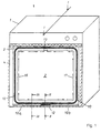
- Fig. 1 shows an oven 1 according to the invention with a Oven muffle 2, an oven door shown in dashed lines 4 and one between the oven door 4 and the Front 3 of the oven muffle 2 arranged door seal 10.
- the hollow profile 11 with a continuous interior trained door seal 10 two sealing strands 10a and 10b, which are essentially the same length and each one half of the circumference of the oven door 4 against the Seal the front 3 of the oven muffle 2.
- the two Sealing strands 10a and 10b each have at their ends a common air inlet opening 12 and a common one Air outlet opening 13, which, based on the lower or upper horizontal section of the door seal 10, are each arranged essentially in the middle.
- the arrows 16 and 17 mark the respective predetermined by the sealing strip 10a or 10b Partial flow path of the cooling air inside the door seal 10th
- the door seal ventilation system 30 which consists of the internally ventilated door seal 10 and one Door seal air duct 20 exists.
- the door seal air duct 20 includes the elements used to cool the The door seal generates and guides the required cooling air the door seal. To do this, it points outside the Oven muffle 2 arranged fan 21, for example a radial fan or a cross flow fan can be and in the case shown between one Oven muffle wall 7 and a rear oven outer plate 6c lies.
- a first flow path section 24 of the door seal air duct 20 for the cooling air from the blower 21 to the door seal 10 is determined by an outflow channel 29a which through the oven muffle wall 7, a lower oven outer plate 6a, the rear oven outer plate 6c and lateral outer sheets is formed.
- the flow path from the blower 21 to the door seal 10 is considered as a whole Pressure side 22 of the door seal air duct 20 designated. There is a pressure side 22 in comparison to the surroundings of the oven 1 increased air pressure.
- the air inlet opening 12 of the door seal 10 is on the pressure side 22 of the door seal air duct 20 is arranged.
- 23 under suction side the path from the door seal 10 to the suction side connection to understand the blower 21.
- the oven muffle wall 7, an upper oven outer plate 6b, the rear Oven outer plate 6c and side outer plates form an inflow channel 29b, which has a second flow path section 28 of the door seal air duct 20 for the cooling air to the blower 21 determined.
- the air outlet 13 of the door seal 10 is on the suction side 23 of the door seal air duct 20 is arranged.
- the cooling of the door seal 10 is effected in that Cooling air due to a between the air inlet opening 12 and the air outlet opening 13 existing air pressure difference flows through the hollow profile 11. It is advantageous if the door seal air duct 20 as shown a defined print page 22 and a defined one Has suction side 23. Due to the arrangement of the air outlet opening 13 on the suction side 23 is the differential pressure and thus increases the flow and the cooling effect.
- a door seal air duct can also be used be, whose blowers the cooling air in the area of the rear oven outer plate 6c immediately sucks the environment, then the air outlet 13 is opened directly into the ambient air, so that the differential pressure only from the overpressure on the pressure side 22 of the air duct 20 results.
- the continuous cooling of the door seal 10 has the significant advantage that even with pyrolysis or other ovens with very high operating temperatures for example based on silicone rubber, can be used without this cooling cannot withstand the high operating temperatures would.
- the cooling air flows in the vertical sections of the door seal 10 from the bottom up
- the thermal flow behavior supports air transportation. Exploiting the thermal flow behavior of air has the advantage that the blower 21 can be made smaller. Also an embodiment in which the inlet opening 12 in the upper horizontal section of the door seal 10 and the outlet opening 13 in the lower horizontal section the door seal 10 is located, however, under May be beneficial.
- the door seal cooling air is thus a subset of the Cooling air of the jacket cooling. This will be part of the heated jacket cooling air on the pressure side 22 of the Blower 21 before leaving the oven 1 on the Door seal air duct 20 of the air inlet opening 12 fed.
- the equipment of the oven 1 with only one of both Door seal and blower cooling fans 21 reduces the space to be accommodated outside the oven muffle 2 technical equipment, lowers manufacturing costs and reduces the need for repairs Oven 1.
- the door seal ventilation system 30 is the pressure side 22 advantageously at the lower horizontal section and the suction side 23 at the upper horizontal section of the Door seal 10 connected. This arrangement will the part of the door seal not used for cooling Jacket cooling air in the lower front area of the oven 1 released into the ambient air. This will Operator looking through the oven door into the oven muffle 2 not from the jacket cooling air flow Blown face.
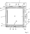
- FIG. 3 and 4 are cross sections through the lower horizontal section the door seal 10 along the lines II-II and III-III from Fig. 1. They illustrate the interaction the door seal 10 and the door seal air duct 20 within the door seal ventilation system 30.
- Fig. 3 shows the connection of the door seal 10 to the door seal air duct 20
- Fig. 4 shows the arrangement outside represents the connection area.
- both figures is designed as a hollow profile 11, with one of the Attachment serving profile extension 14 equipped
- Door seal 10 can be seen by means of an oven door side provided, cross-section hook-shaped mounting rail 8 is attached to the oven door 4.
- the oven door 4 has a suitable groove for receiving the door seal so that it does not protrude so far.
- the storage in a groove has a warping effect and thermal expansion-related migration of the door seal opposite.
- Fig. 3 is the air inlet opening 12 of the door seal 10 seen in cross section. It can be clearly seen that the hollow profile 11 of the door seal 10 on one side Air inlet opening 12 is open.
- the air inlet opening 12 has a thickened sealing edge 15 on the ring-shaped in the spatial training is, for example, lip-shaped or bead-like can be.
- the sealing edge 15 acts with an air duct side provided sealing surface 25 under training a closed connection space 18 together in such a way that he closes the oven door 4 against the from the front 3 of the oven muffle 2 and the lower one Oven outer plate 6a formed sealing surface 25 pressed and forms a flat connection contact with it.
- the cooling air enters the terminal space 18 and thus in the air inlet opening 12 of the door seal 10.
- FIG 4 shows one outside the air inlet opening 12 lying cross section through the lower horizontal section the door seal 10. It can be seen that the Door seal 10 formed here without an exit gap Sealing surface 25 is present.
- the figure shows optional here existing, for example, slit-shaped Outlet openings 26 on the front of the lower outer plate 6a, through which part of the cooling air which the Jacket cooling of the oven muffle 2 is used in the ambient air exit.
- the cooling air throughput depends on the door seal 10 of numerous influencing factors, in particular of the strength of the blower 21, the cross section of the outflow channel 29a, the dimension of the outlet gap 31, the Size of the air inlet opening 12, the diameter of the Hollow profile 11 and the dimensions of the optional outlet openings 26 from.
- the influencing factors can Specialist in order to vary in order the required cooling air throughput through the door seal and the cooling air flow rate that may be required to realize for jacket cooling.
Abstract
Description
Die Erfindung betrifft einen Backofen mit einer Backofenmuffel, einer Backofentür und einer zwischen Backofentür und Frontseite der Backofenmuffel angeordneten Türdichtung.The invention relates to an oven with an oven muffle, one oven door and one between the oven door and the front of the oven muffle arranged door seal.
Türdichtungen für Backöfen, die die Backofentür gegen die Frontseite der Backofenmuffel abdichten, sind in vielen Ausführungsformen bekannt. Sie sind an der Frontseite der Backofenmuffel oder an der Backofentür angebracht und entweder als abgewinkelte, seitlich offene Silikonschläuche oder als Metallgewebestränge ausgebildet.Door seals for ovens that lock the oven door against the Sealing the front of the oven muffle are in many Embodiments known. You are at the front of the Oven muffle or attached to the oven door and either as angled, laterally open silicone hoses or designed as metal mesh strands.
Im Stand der Technik ist vor allem bei herkömmlichen Backöfen ohne pyrolytische Selbstreinigung der Einbau von Silikondichtungen standardmäßig vorgesehen, da sie einfach und kostengünstig herzustellen sind, eine relativ geringe Wärmeausdehnung haben und eine sehr gute Abdichtwirkung aufweisen. Außerdem ist bei Silikondichtungen vorteilhaft, daß sie aufgrund ihrer glatten Oberfläche leicht zu reinigen sind. Die von Silikondichtungen maximal verträglichen Temperaturen von 250 bis 270°C sind jedoch relativ niedrig. Sie werden deshalb in der Regel nicht in Backöfen mit pyrolytischer Selbstreinigung (im folgenden als Pyrolysegeräte bezeichnet) eingesetzt, bei denen Betriebstemperaturen bis zu 550°C auftreten.The state of the art is mostly conventional Ovens without pyrolytic self-cleaning the installation of Silicone seals are provided by default as they are simple and are inexpensive to manufacture, a relative have low thermal expansion and a very good sealing effect exhibit. Also with silicone seals advantageous that they are due to their smooth surface are easy to clean. The maximum of silicone seals tolerable temperatures of 250 to 270 ° C are however relatively low. Therefore, you will usually not in ovens with pyrolytic self-cleaning (in hereinafter referred to as pyrolysis equipment) used where operating temperatures up to 550 ° C occur.
Soweit in Einzelfällen Silikondichtungen auch bei Pyrolysegeräten verwendet wurden, war dies mit einem erheblichen konstruktiven Aufwand verbunden, um die Gerätefront so auszubilden, daß im Bereich der Dichtung ausreichend niedrige Temperaturen herrschen, d.h. die von Silikondichtungen maximal verträglichen Grenztemperaturen von 250 bis 270°C nicht überschritten werden.So far, in individual cases, silicone seals also for pyrolysis devices were used, this was with a significant design effort connected to the front of the device to be designed so that sufficient in the area of the seal low temperatures prevail, i.e. that of silicone seals maximum tolerable limit temperatures of Do not exceed 250 to 270 ° C.
Aus diesem Grund werden bei Pyrolysegeräten derzeit meistens mit Glasgewebe gefüllte Metallgewebedichtungen eingesetzt, die den während der pyrolytischen Selbstreinigung herrschenden sehr hohen Betriebstemperaturen standhalten. Aufgrund der hohen Wärmeausdehnung dieses Dichtungstyps müssen jedoch bei der Befestigung der Dichtung besondere Vorkehrungen getroffen werden, um eine zufriedenstellende Abdichtung zu gewährleisten. Außerdem sind diese Dichtungen schwer von in ihre poröse Oberflächenstruktur eingedrungenem Fett zu reinigen und verhärten mit der Zeit, wodurch die Dichtwirkung nachläßt. Darüber hinaus ist die Montage schwierig.For this reason, pyrolysis devices are currently mostly used metal mesh seals filled with glass mesh are used, that during pyrolytic self-cleaning withstand the very high operating temperatures. Due to the high thermal expansion of this type of seal however, when attaching the seal Special arrangements are made to ensure satisfactory To ensure sealing. Also are these seals are heavy in their porous surface structure cleaned and hardened grease with time, which reduces the sealing effect. About that assembly is also difficult.
Der Erfindung liegt unter Berücksichtigung des genannten Standes der Technik das technische Problem zugrunde, einen Backofen mit verbesserter Türdichtung, insbesondere für Pyrolysegeräte oder andere Backöfen mit sehr hohen Betriebstemperaturen zu schaffen.The invention lies in consideration of the above State of the art based on the technical problem, an oven with improved door seal, in particular for pyrolysis devices or other ovens with very high To create operating temperatures.
Dieses Problem wird bei einem Backofen der eingangs beschriebenen Art dadurch gelöst, daß er ein Türdichtungslüftungssystem zur Kühlung der Türdichtung mit in ihrem Innern strömender Luft aufweist. Dabei ist die Türdichtung als Hohlprofil mit einem durchgehenden Innenraum ausgebildet und weist eine Lufteintrittsöffnung und eine Luftaustrittsöffnung auf. Eine Türdichtungsluftführung mit einem Gebläse ist vorgesehen, um im Bereich der Lufteintrittsöffnung der Türdichtung einen höheren Luftdruck als im Bereich der Luftaustrittsöffnung der Türdichtung zu erzeugen, so daß Kühlluft aufgrund der Luftdruckdifferenz zwangsgeführt durch den Innenraum der Türdichtung strömt.This problem is in an oven of the type described Art solved in that he has a door seal ventilation system for cooling the door seal with in your Air flowing inside. Here is the door seal as a hollow profile with a continuous interior formed and has an air inlet opening and Air outlet opening. A door seal air duct with a blower is provided in the area of the air inlet opening the door seal has a higher air pressure than in the area of the air outlet opening of the door seal generate so that cooling air due to the air pressure difference positively guided through the interior of the door seal flows.
Bestandteile der Erfindung sind somit eine als Hohlprofil ausgebildete Türdichtung und eine darauf abgestimmte Luftführung, die man insgesamt als Türdichtungslüftungssystem bezeichnen kann. Durch die im Inneren des Hohlprofils strömende Luft können die auf die Türdichtung einwirkenden Temperaturen auch bei höheren Betriebstemperaturen des Backofens so niedrig gehalten werden, daß die vom jeweiligen Dichtungsmaterial maximal verträglichen Temperaturen nicht überschritten werden. Dadurch wird einer durch hohe Temperaturen bedingten Materialschwächung entgegengewirkt und somit die Lebensdauer der Türdichtung erhöht. Außerdem ist es möglich, Materialien mit sehr guten Dichtungseigenschaften, aber relativ niedrigen maximal verträglichen Temperaturen standardmäßig in Backöfen einzusetzen. Die als Hohlprofil ausgebildete Türdichtung ist bevorzugt seitlich geschlossen.Components of the invention are thus a hollow profile trained door seal and a coordinated Air routing, which is generally called a door seal ventilation system can designate. By the inside of the hollow profile flowing air can act on the door seal Temperatures even at higher operating temperatures of the oven are kept so low that the maximum compatible with the respective sealing material Temperatures are not exceeded. This makes one weakening of material due to high temperatures counteracted and thus the life of the door seal elevated. It is also possible to use materials with a lot good sealing properties, but relatively low maximum tolerable temperatures as standard in ovens to use. The door seal designed as a hollow profile is preferably closed on the side.
Die Elemente und Merkmale der nachfolgenden Erläuterung der Erfindung und der abhängigen Patentansprüche können einzeln oder in Kombination miteinander eingesetzt werden.The elements and features of the explanation below the invention and the dependent claims can be used individually or in combination.
Für die Funktion der Türdichtung genügt es, wenn sie eine einzige Lufteintrittsöffnung zum Eintritt der durch die Türdichtungsluftführung erzeugten und zu der Lufteintrittsöffnung geführten Kühlluft und eine einzige Luftaustrittsöffnung zum Austritt der durch die Türdichtung geströmten Kühlluft aufweist. Es ist jedoch selbstverständlich, daß die Türdichtung auch mehrere Lufteintrittsöffnungen und/oder Luftaustrittsöffnungen umfassen kann. Aus Gründen der Verständlichkeit wird im folgenden jedoch überwiegend von "der Lufteintrittsöffnung" und "der Luftaustrittsöffnung" gesprochen.For the function of the door seal, it is sufficient if it has one only air inlet opening to enter through the Door seal air duct generated and to the air inlet opening guided cooling air and a single air outlet to exit through the door seal has flowed cooling air. However, it goes without saying that the door seal also has several air inlet openings and / or include air outlet openings can. For the sake of clarity, the following is however predominantly from "the air inlet opening" and "the air outlet opening" spoken.
Die Türdichtung kann prinzipiell einteilig ausgebildet sein. Dabei liegen die Lufteintrittsöffnung und die Luftaustrittsöffnung im wesentlichen nebeneinander. Eine einteilige Ausbildung der Türdichtung führt jedoch dazu, daß sich in Strömungsrichtung der Kühlluft ein starker Temperaturgradient ausbildet. Deshalb ist die Türdichtung bevorzugt in zwei Dichtungsstränge aufgeteilt, wobei jeder Dichtungsstrang als Hohlprofil mit einem durchgehenden Innenraum ausgebildet ist und jeweils mindestens eine Lufteintrittsöffnung und mindestens eine Luftaustrittsöffnung aufweist. Dabei liegen die jeweils entsprechenden Lufteintrittsöffnungen und die jeweils entsprechenden Luftaustrittsöffnungen der Dichtungsstränge in Bereichen mit jeweils gleichem Luftdruck.The door seal can in principle be made in one piece be. The air inlet opening and the air outlet opening are located here essentially side by side. A one piece Training the door seal, however, leads to the fact that there is a strong temperature gradient in the direction of flow of the cooling air trains. Therefore the door seal is preferred divided into two sealing strands, each Sealing strip as a hollow profile with a continuous Interior is formed and at least one each Air inlet opening and at least one air outlet opening having. The corresponding ones are in each case Air inlet openings and the corresponding ones Air outlet openings of the sealing strands in areas with the same air pressure.
Um eine gleichmäßige Durchströmung und damit Kühlung der Türdichtung zu realisieren, ist es bei einer in zwei Dichtungsstränge aufgeteilten Türdichtung ferner vorteilhaft, wenn beide Stränge im wesentlichen gleich lang sind, d.h. jeweils eine Hälfte des Umfanges der Backofentür gegen die Frontseite der Backofenmuffel abdichten. Dabei kann an den jeweils entsprechenden Enden eine gemeinsame Lufteintrittsöffnung und/oder eine gemeinsame Luftaustrittsöffnung vorhanden sein. To ensure an even flow and thus cooling the Realizing the door seal is one in two Seal strands divided door seal further advantageous if both strands are essentially the same length are, i.e. one half of the circumference of the oven door seal against the front of the oven muffle. It can be a common at the corresponding ends Air inlet opening and / or a common one Air outlet opening should be available.
Eine vorteilhafte Ausbildung der Türdichtung kann vorsehen, daß sie an ihrer Lufteintrittsöffnung und/oder ihrer Luftaustrittsöffnung zum Anschließen der Türdichtung an die Türdichtungsluftführung einen Dichtrand aufweist. Dieser Dichtrand wirkt mit einer an dem dichtungsseitigen Ende der Türdichtungsluftführung vorgesehenen, der Lufteintritts- und/oder Luftaustrittsöffnung gegenüberliegenden Dichtfläche zusammen. Dadurch wird ein geschlossener Anschlußraum gebildet und eine Zwangsführung der Kühlluft und somit ein zur Kühlung der Türdichtung ausreichend großer Luftübergang zwischen der Türdichtungsluftführung und der Lufteintrittsöffnung und/oder der Luftaustrittsöffnung bewirkt.An advantageous design of the door seal can provide that they are at their air inlet opening and / or their Air outlet opening for connecting the door seal the door seal air duct has a sealing edge. This sealing edge works with one on the seal side Provided end of the door seal air duct, opposite the air inlet and / or air outlet opening Sealing surface together. This makes a closed one Connection space formed and a forced routing of the cooling air and therefore sufficient to cool the door seal large air transition between the door seal air duct and the air inlet opening and / or the air outlet opening causes.
Ein gut dichtender Anschluß der Lufteintritts- und/oder Luftaustrittsöffnungen der Türdichtung an die Türdichtungsluftführung ist besonders dann von Vorteil, wenn die Türdichtung, wie vorzugsweise vorgeschlagen wird, an der Backofentür angebracht ist und somit eine größere konstruktive und räumliche Trennung von Dichtung und Luftzufuhr besteht als bei einer an der Frontseite der Backofenmuffel befestigten Türdichtung. Eine Befestigung der innenbelüfteten Türdichtung an der Frontseite der Backofenmuffel ist ebenfalls möglich.A well sealing connection of the air inlet and / or Air outlet openings of the door seal to the door seal air duct is particularly advantageous if the Door seal, as is preferably suggested, on the Oven door is attached and thus a larger constructive and spatial separation of seal and air supply exists as with one on the front of the oven muffle attached door seal. An attachment of the Ventilated door seal on the front of the oven muffle is also possible.
Zum Austritt der Kühlluft aus der Türdichtung kann die Luftaustrittsöffnung auch als eine beispielsweise loch- oder schlitzförmige Materialausnehmung ohne speziell ausgeformten Dichtrand realisiert sein. Entsprechendes kann für die Realisierung der Lufteintrittsöffnung gelten.The air can exit the cooling air from the door seal Air outlet opening as a hole or for example slot-shaped material recess without a specially shaped one Sealing edge be realized. The same can apply to the realization of the air inlet opening.
Aufgrund der oben genannten Vorteile von Silikondichtungen enthält die innenbelüftete Türdichtung eines erfindungsgemäßen Backofens bevorzugt ebenfalls Silikongummi. Because of the above advantages of silicone seals contains the ventilated door seal of an inventive Ovens also prefer silicone rubber.
Besonders bevorzugt besteht sie überwiegend oder praktisch vollständig aus diesem Material.It is particularly preferably predominant or practical entirely from this material.
Um einen ausreichend großen Luftdurchsatz und damit eine ausreichende Kühlung der Türdichtung zu gewährleisten, beträgt der Innendurchmesser des Hohlprofils ca. 6 bis 8 mm. Der äußere Durchmesser mißt etwa 10 bis 12 mm.To have a sufficiently large air flow and therefore one to ensure adequate cooling of the door seal, the inside diameter of the hollow profile is approx. 6 to 8 mm. The outer diameter measures approximately 10 to 12 mm.
Es ist von Vorteil, wenn die Lufteintrittsöffnung in dem unteren Horizontalabschnitt der Türdichtung und die Luftaustrittsöffnung in dem oberen Horizontalabschnitt der Türdichtung liegt. Durch diese Anordnung wird erreicht, daß die Luft im Innern der Türdichtung von unten nach oben strömt.It is advantageous if the air inlet opening in the lower horizontal section of the door seal and the air outlet opening in the upper horizontal section of the Door seal lies. This arrangement achieves that the air inside the door seal from below streams up.
In den Zeichnungen ist ein Ausführungsbeispiel des erfindungsgemäßen Backofens schematisch dargestellt; es zeigen:
- Fig. 1
- eine perspektivische Frontansicht des Backofens mit innenbelüfteter Türdichtung,
- Fig. 2
- einen Querschnitt durch den Backofen entlang der Linie I-I aus Fig. 1,
- Fig. 3
- einen ausschnittsweisen Querschnitt durch das Türdichtungslüftungssystem des Backofens entlang der Linie II-II aus Fig. 1,
- Fig. 4
- einen ausschnittsweisen Querschnitt durch das Türdichtungslüftungssystem des Backofens entlang der Linie III-III aus Fig. 1.
- Fig. 1
- a perspective front view of the oven with ventilated door seal,
- Fig. 2
- 3 shows a cross section through the oven along the line II from FIG. 1,
- Fig. 3
- a partial cross section through the door seal ventilation system of the oven along the line II-II of Fig. 1,
- Fig. 4
- a partial cross section through the door seal ventilation system of the oven along the line III-III of Fig. 1st
Fig. 1 zeigt einen erfindungsgemäßen Backofen 1 mit einer
Backofenmuffel 2, einer gestrichelt dargestellten Backofentür
4 und einer zwischen der Backofentür 4 und der
Frontseite 3 der Backofenmuffel 2 angeordneten Türdichtung
10. In der dargestellten bevorzugten Ausführungsform
weist die als Hohlprofil 11 mit durchgehendem Innenraum
ausgebildete Türdichtung 10 zwei Dichtungsstränge 10a und
10b auf, die im wesentlichen gleich lang sind und jeweils
eine Hälfte des Umfanges der Backofentür 4 gegen die
Frontseite 3 der Backofenmuffel 2 abdichten. Die beiden
Dichtungsstränge 10a und 10b haben an ihren Enden jeweils
eine gemeinsame Lufteintrittsöffnung 12 und eine gemeinsame
Luftaustrittsöffnung 13, die, bezogen auf den unteren
bzw. oberen Horizontalabschnitt der Türdichtung 10,
jeweils im wesentlichen mittig angeordnet sind. Selbstverständlich
können jeweils auch mehrere Lufteintrittsöffnungen
12 und/oder Luftaustrittsöffnungen 13 vorgesehen
sein. Die Pfeile 16 bzw. 17 markieren den jeweiligen,
durch den Dichtungsstrang 10a bzw. 10b vorgegebenen
Teil-Strömungsweg der Kühlluft innerhalb der Türdichtung
10.Fig. 1 shows an
In dem in Fig. 2 dargestellten Querschnitt durch den
Backofen entlang der Linie I-I aus Fig. 1 sind weitere
Details des Türdichtungslüftungssystems 30 zu erkennen,
welches aus der innenbelüfteten Türdichtung 10 und einer
Türdichtungsluftführung 20 besteht. Die Türdichtungsluftführung
20 umfaßt die Elemente, die die zur Kühlung der
Türdichtung erforderliche Kühlluft erzeugen und führt sie
der Türdichtung zu. Dazu weist sie ein außerhalb der
Backofenmuffel 2 angeordnetes Gebläse 21 auf, das beispielweise
ein Radialgebläse oder ein Querstromgebläse
sein kann und in dem dargestellten Fall zwischen einer
Backofenmuffelwand 7 und einem rückwärtigen Backofen-Außenblech
6c liegt. In the cross section shown in Fig. 2 through the
Ovens along the line I-I of Fig. 1 are others
Recognize details of the door
Ein erster Strömungswegabschnitt 24 der Türdichtungsluftführung
20 für die Kühlluft vom Gebläse 21 zur Türdichtung
10 wird durch einen Ausströmkanal 29a bestimmt, der
durch die Backofenmuffelwand 7, ein unteres Backofen-Außenblech
6a, das rückwärtige Backofen-Außenblech 6c und
seitliche Außenbleche gebildet wird. Der Strömungsweg von
dem Gebläse 21 zu der Türdichtung 10 wird insgesamt als
Druckseite 22 der Türdichtungsluftführung 20 bezeichnet.
An der Druckseite 22 herrscht ein im Vergleich zu der Umgebung
des Backofens 1 erhöhter Luftdruck. Die Lufteintrittsöffnung
12 der Türdichtung 10 ist auf der Druckseite
22 der Türdichtungsluftführung 20 angeordnet.A first
In der dargestellten bevorzugten Ausführungsform weist
die Türdichtungsluftführung 20 des Backofens 1 zusätzlich
zu der Druckseite 22 auch eine definierte Saugseite 23
mit einem im Vergleich zu der Umgebung des Backofens 1
erniedrigten Luftdruck auf. Dabei ist unter Saugseite 23
der Weg von der Türdichtung 10 zu dem saugseitigen Anschluß
des Gebläses 21 zu verstehen. Die Backofenmuffelwand
7, ein oberes Backofen-Außenblech 6b, das rückwärtige
Backofen-Außenblech 6c und seitliche Außenbleche
bilden einen Einströmkanal 29b, der einen zweiten Strömungswegabschnitt
28 der Türdichtungsluftführung 20 für
die Kühlluft zum Gebläse 21 hin bestimmt. Die Luftaustrittsöffnung
13 der Türdichtung 10 ist auf der Saugseite
23 der Türdichtungsluftführung 20 angeordnet.In the preferred embodiment shown, points
the door
Die Kühlung der Türdichtung 10 wird dadurch bewirkt, daß
Kühlluft aufgrund einer zwischen der Lufteintrittsöffnung
12 und der Luftaustrittsöffnung 13 bestehenden Luftdruckdifferenz
durch das Hohlprofil 11 strömt. Dabei ist es
vorteilhaft, wenn die Türdichtungsluftführung 20 wie dargestellt
eine definierte Druckseite 22 und eine definierte
Saugseite 23 hat. Durch die Anordnung der Luftaustrittsöffnung
13 auf der Saugseite 23 wird der Differenzdruck
und somit die Strömung und die Kühlwirkung erhöht.The cooling of the
Generell kann auch mit einer Türdichtungsluftführung gearbeitet
werden, deren Gebläse die Kühlluft im Bereich
des rückwärtigen Backofen-Außenbleches 6c unmittelbar aus
der Umgebung ansaugt, wobei dann die Luftaustrittsöffnung
13 unmittelbar in die Umgebungsluft geöffnet ist, so daß
der Differenzdruck nur aus dem Überdruck auf der Druckseite
22 der Luftführung 20 resultiert.In general, a door seal air duct can also be used
be, whose blowers the cooling air in the area
of the rear oven outer plate 6c immediately
sucks the environment, then the
Die kontinuierliche Kühlung der Türdichtung 10 hat den
wesentlichen Vorteil, daß auch bei Pyrolysegeräten oder
anderen Backöfen mit sehr hohen Betriebstemperaturen Türdichtungsmaterialien,
beispielsweise basierend auf Silikongummi,
eingesetzt werden können, die ohne diese Kühlung
den hohen Betriebstemperaturen nicht standhalten
würden.The continuous cooling of the
Bei der dargestellten Ausführungsform strömt die Kühlungsluft
in den vertikalen Abschnitten der Türdichtung
10 von unten nach oben, wobei das thermische Strömungsverhalten
den Lufttransport unterstützt. Das Ausnutzen
des thermischen Strömungsverhaltens der Luft hat den Vorteil,
daß das Gebläse 21 kleiner ausgeführt werden kann.
Auch eine Ausführungsform, bei der sich die Eintrittsöffnung
12 in dem oberen Horizontalabschnitt der Türdichtung
10 und die Austrittsöffnung 13 in dem unteren Horizontalabschnitt
der Türdichtung 10 befindet, kann jedoch unter
Umständen vorteilhaft sein.In the illustrated embodiment, the cooling air flows
in the vertical sections of the
In der dargestellten bevorzugten Ausführungsform dient
ein für eine Mantelkühlung der Backofenmuffel 2 vorgesehenes
Gebläse 21 zugleich als Gebläse 21 der Türdichtungsluftführung
20. Die bei vielen Backöfen vorhandene
Mantelkühlung kühlt die Backofenmuffel 2 nach außen hin
und beugt somit Hitzeschäden an der Backofentechnik sowie
den angrenzenden Möbeln vor. In dieser Ausführungsform
ist die Türdichtungskühlluft somit eine Teilmenge der
Kühlluft der Mantelkühlung. Dabei wird ein Teil der bereits
erwärmten Mantelkühlluft an der Druckseite 22 des
Gebläses 21 vor dem Verlassen des Backofens 1 über die
Türdichtungsluftführung 20 der Lufteintrittsöffnung 12
zugeführt.In the preferred embodiment shown serves
one intended for jacket cooling of the
Die Ausstattung des Backofens 1 mit nur einem sowohl der
Türdichtung- als auch der Mantelkühlung dienenden Gebläse
21 reduziert die außerhalb der Backofenmuffel 2 unterzubringende
technische Ausrüstung, erniedrigt die Herstellungskosten
und verringert die Reparaturanfälligkeit des
Backofens 1. Bei einer derartigen Realisierung des Türdichtungslüftungssystems
30 ist die Druckseite 22 vorteilhafterweise
an dem unteren Horizontalabschnitt und
die Saugseite 23 an dem oberen Horizontalabschnitt der
Türdichtung 10 angeschlossen. Durch diese Anordnung wird
der nicht der Türdichtungskühlung dienende Anteil der
Mantelkühlungsluft in dem unteren Frontbereich des Backofens
1 an die Umgebungsluft abgegeben. Dadurch wird dem
Bediener bei dem Blick durch die Backofentür in die Backofenmuffel
2 nicht von dem Mantelkühlungsluftstrom ins
Gesicht geblasen.The equipment of the
Fig. 3 und 4 sind Querschnitte durch den unteren Horizontalabschnitt
der Türdichtung 10 entlang der Linien II-II
und III-III aus Fig. 1. Sie verdeutlichen das Zusammenwirken
der Türdichtung 10 und der Türdichtungsluftführung
20 innerhalb des Türdichtungslüftungssystems 30. Dabei
zeigt Fig. 3 den Anschluß der Türdichtung 10 an die Türdichtungsluftführung
20, während Fig. 4 die Anordnung außerhalb
des Anschlußbereiches darstellt. In beiden Figuren
ist die als Hohlprofil 11 ausgebildete, mit einem der
Befestigung dienenden Profilfortsatz 14 ausgestattete
Türdichtung 10 zu erkennen, die mittels einer backofentürseitig
vorgesehenen, im Querschnitt hakenförmigen Befestigungsschiene
8 an der Backofentür 4 befestigt ist.
Die Backofentür 4 weist eine passende Nut zur Aufnahme
der Türdichtung auf, damit diese nicht so weit hervorsteht.
Außerdem wirkt die Lagerung in einer Nut dem Verziehen
und wärmeausdehnungsbedingten Wandern der Türdichtung
entgegen.3 and 4 are cross sections through the lower horizontal section
the
In Fig. 3 ist die Lufteintrittsöffnung 12 der Türdichtung
10 im Querschnitt zu sehen. Deutlich zu erkennen ist, daß
das Hohlprofil 11 der Türdichtung 10 einseitig zu der
Lufteintrittsöffnung 12 geöffnet ist. Zum Anschließen der
Lufteintrittsöffnung 12 an die Türdichtungsluftführung 20
weist die Lufteintrittsöffnung 12 einen verdickten Dichtrand
15 auf, der in der räumlichen Ausbildung ringförmig
ist und beispielsweise lippenförmig oder wulstartig geformt
sein kann. Der Dichtrand 15 wirkt mit einer luftführungsseitig
vorgesehenen Dichtfläche 25 unter Ausbildung
eines geschlossenen Anschlußraumes 18 derart zusammen,
daß er beim Schließen der Backofentür 4 gegen die
von der Frontseite 3 der Backofenmuffel 2 und dem unteren
Backofen-Außenblech 6a gebildete Dichtfläche 25 gedrückt
wird und mit dieser einen ebenen Anschlußkontakt bildet.
Durch einen zwischen der Backofenmuffelwand 7 und dem unteren
Backofen-Außenblech 6a im Bereich der Dichtfläche
verbleibenden Austrittsspalt 31, dessen Abmessungen an
die Größe der Lufteintrittsöffnung 12 angepaßt sind,
tritt die Kühlluft in den Anschlußraum 18 und somit in
die Lufteintrittsöffnung 12 der Türdichtung 10 ein.In Fig. 3 is the air inlet opening 12 of the
Der gegebenenfalls vorhandene Anschluß der Luftaustrittsöffnung
13 an die Saugseite 23 der Türdichtungsluftführung
20 kann dem oben beschriebenen Anschluß der Lufteintrittsöffnung
an die Türdichtungsluftführung 20 entsprechend
ausgebildet sein.The possible connection of the air outlet opening
13 to the
Fig. 4 zeigt einen außerhalb der Lufteintrittsöffnung 12
liegenden Querschnitt durch den unteren Horizontalabschnitt
der Türdichtung 10. Es ist zu erkennen, daß die
Türdichtung 10 an der hier ohne Austrittsspalt ausgebildeten
Dichtfläche 25 anliegt. Die Figur zeigt hier optional
vorhandene, beispielsweise schlitzförmig ausgebildete
Austrittsöffnungen 26 an der Frontseite des unteren Außenbleches
6a, durch die ein Teil der Kühlluft, die der
Mantelkühlung der Backofenmuffel 2 dient, in die Umgebungsluft
austritt.4 shows one outside the
Insgesamt hängt der Kühlluftdurchsatz durch die Türdichtung
10 von zahlreichen Einflußfaktoren, insbesondere von
der Stärke des Gebläses 21, dem Querschnitt des Ausströmkanales
29a, der Abmessung des Austrittsspaltes 31, der
Größe der Lufteintrittsöffnung 12, dem Durchmesser des
Hohlprofils 11 und den Abmessungen der optionalen Austrittsöffnungen
26 ab. Diese Einflußfaktoren kann der
Fachmann in ihm geläufiger Art und Weise variieren, um
den benötigten Kühlluftdurchsatz durch die Türdichtung
und den gegebenenfalls erforderlichen Kühlluftdurchsatz
für die Mantelkühlung zu realisieren.Overall, the cooling air throughput depends on the
Claims (12)
dadurch gekennzeichnet, daß
er ein Türdichtungslüftungssystem (30) zur Kühlung der Türdichtung (10) mit in ihrem Inneren strömender Luft aufweist, wobei
characterized in that
he has a door seal ventilation system (30) for cooling the door seal (10) with air flowing inside, wherein
Applications Claiming Priority (2)
| Application Number | Priority Date | Filing Date | Title |
|---|---|---|---|
| DE19641109 | 1996-10-05 | ||
| DE19641109A DE19641109A1 (en) | 1996-10-05 | 1996-10-05 | Oven with ventilated door seal |
Publications (2)
| Publication Number | Publication Date |
|---|---|
| EP0834701A1 true EP0834701A1 (en) | 1998-04-08 |
| EP0834701B1 EP0834701B1 (en) | 2001-11-28 |
Family
ID=7807952
Family Applications (1)
| Application Number | Title | Priority Date | Filing Date |
|---|---|---|---|
| EP97115980A Expired - Lifetime EP0834701B1 (en) | 1996-10-05 | 1997-09-13 | Baking oven with internally ventilated door seal |
Country Status (3)
| Country | Link |
|---|---|
| EP (1) | EP0834701B1 (en) |
| DE (2) | DE19641109A1 (en) |
| ES (1) | ES2168561T3 (en) |
Cited By (4)
| Publication number | Priority date | Publication date | Assignee | Title |
|---|---|---|---|---|
| DE19806281A1 (en) * | 1998-02-16 | 1999-08-19 | Bosch Siemens Hausgeraete | Attachments for door seal of kitchen oven, produced at minimal cost and effort |
| WO2005008138A1 (en) | 2003-07-21 | 2005-01-27 | Lg Electronics,Inc. | Air flow system in oven |
| EP2505924A1 (en) | 2011-03-30 | 2012-10-03 | Electrolux Home Products Corporation N.V. | A cooking oven with a front frame and an oven door swivel-mounted at said front frame |
| EP2905542A1 (en) * | 2014-02-11 | 2015-08-12 | BSH Hausgeräte GmbH | Cooling of door components |
Families Citing this family (2)
| Publication number | Priority date | Publication date | Assignee | Title |
|---|---|---|---|---|
| DE19935836C2 (en) * | 1999-07-29 | 2001-08-09 | Bsh Bosch Siemens Hausgeraete | Cooking appliance with a sealing profile and corresponding sealing profile |
| DE10208334B4 (en) * | 2002-02-27 | 2020-12-17 | BSH Hausgeräte GmbH | Home appliance |
Citations (4)
| Publication number | Priority date | Publication date | Assignee | Title |
|---|---|---|---|---|
| US3812316A (en) * | 1973-03-28 | 1974-05-21 | Gen Electric | Door seal gasket for combined microwave and self-cleaning oven |
| DE2929837B1 (en) * | 1979-07-23 | 1981-01-15 | Donges Stahlbau Gmbh | Tubular edge strip for power operated gate leaves or the like. |
| US4601279A (en) * | 1984-07-10 | 1986-07-22 | Societe De Dietrich | Pyrolytic self-cleaning domestic oven with improved means for protecting electronic panel and controls from heat damages |
| US5085204A (en) * | 1991-07-17 | 1992-02-04 | Moyer James D | Mounting of door gasket |
Family Cites Families (5)
| Publication number | Priority date | Publication date | Assignee | Title |
|---|---|---|---|---|
| US3384067A (en) * | 1966-07-25 | 1968-05-21 | Norris Thermador Corp | Forced air cooling and ventilating system for self-cleaning oven |
| DE8707959U1 (en) * | 1986-06-13 | 1987-10-15 | Exte-Extrudertechnik Gmbh, 5272 Wipperfuerth, De | |
| DE9015034U1 (en) * | 1990-11-01 | 1991-11-14 | Phoenix Ag, 2100 Hamburg, De | |
| GB2262601B (en) * | 1991-12-19 | 1995-02-08 | Stoves Ltd | Improvements in and relating to cookers |
| DE9409895U1 (en) * | 1994-06-18 | 1994-09-08 | Wiesheu Wiwa Gmbh | Oven for heat treatment of food |
-
1996
- 1996-10-05 DE DE19641109A patent/DE19641109A1/en not_active Withdrawn
-
1997
- 1997-09-13 DE DE59705523T patent/DE59705523D1/en not_active Expired - Fee Related
- 1997-09-13 EP EP97115980A patent/EP0834701B1/en not_active Expired - Lifetime
- 1997-09-13 ES ES97115980T patent/ES2168561T3/en not_active Expired - Lifetime
Patent Citations (4)
| Publication number | Priority date | Publication date | Assignee | Title |
|---|---|---|---|---|
| US3812316A (en) * | 1973-03-28 | 1974-05-21 | Gen Electric | Door seal gasket for combined microwave and self-cleaning oven |
| DE2929837B1 (en) * | 1979-07-23 | 1981-01-15 | Donges Stahlbau Gmbh | Tubular edge strip for power operated gate leaves or the like. |
| US4601279A (en) * | 1984-07-10 | 1986-07-22 | Societe De Dietrich | Pyrolytic self-cleaning domestic oven with improved means for protecting electronic panel and controls from heat damages |
| US5085204A (en) * | 1991-07-17 | 1992-02-04 | Moyer James D | Mounting of door gasket |
Cited By (6)
| Publication number | Priority date | Publication date | Assignee | Title |
|---|---|---|---|---|
| DE19806281A1 (en) * | 1998-02-16 | 1999-08-19 | Bosch Siemens Hausgeraete | Attachments for door seal of kitchen oven, produced at minimal cost and effort |
| WO2005008138A1 (en) | 2003-07-21 | 2005-01-27 | Lg Electronics,Inc. | Air flow system in oven |
| EP1649220A1 (en) * | 2003-07-21 | 2006-04-26 | LG Electronics, Inc. | Air flow system in oven |
| EP1649220A4 (en) * | 2003-07-21 | 2012-02-15 | Lg Electronics Inc | Air flow system in oven |
| EP2505924A1 (en) | 2011-03-30 | 2012-10-03 | Electrolux Home Products Corporation N.V. | A cooking oven with a front frame and an oven door swivel-mounted at said front frame |
| EP2905542A1 (en) * | 2014-02-11 | 2015-08-12 | BSH Hausgeräte GmbH | Cooling of door components |
Also Published As
| Publication number | Publication date |
|---|---|
| EP0834701B1 (en) | 2001-11-28 |
| DE19641109A1 (en) | 1998-04-09 |
| ES2168561T3 (en) | 2002-06-16 |
| DE59705523D1 (en) | 2002-01-10 |
Similar Documents
| Publication | Publication Date | Title |
|---|---|---|
| EP2834094A1 (en) | Air duct system for a rail vehicle of passenger traffic | |
| EP2440732B1 (en) | Door sealing system | |
| DE19649073C2 (en) | Device for cooling extruded profiles | |
| EP0834701B1 (en) | Baking oven with internally ventilated door seal | |
| DE202005002132U1 (en) | Frame assembly and air flow limiting device for this purpose | |
| DE4404165C1 (en) | Method and devices for contact tempering a glass sheet | |
| DE2609030B2 (en) | Method and device for guiding air currents emerging from an air-permeable, in particular perforated surface | |
| DE102005006010A1 (en) | Frame assembly and air flow limiting device for this purpose | |
| DE10018268A1 (en) | Airflow control element of heating or conditioning system of motor vehicle has one edge of louver-type airflow control element irregularly constructed and may be serrated or notched | |
| DE2033195C3 (en) | Air outlet device for air conditioning systems | |
| AT514377B1 (en) | air outlet | |
| EP1445230A2 (en) | Elevator shaft door and method for fulfilling fire protection requirements and installing said door | |
| EP2267263A2 (en) | Door seal | |
| DE102008042803A1 (en) | Air flow guiding device for use in e.g. air conditioning system, of building, has two guidance sections, where lower edge of one section, which path-breaks exhaust slot, stands deeper than lower edge of other section pointing to slot | |
| DE2817915C2 (en) | Device for removing exhaust air from buildings | |
| EP1005621B1 (en) | Ventilator for window elements | |
| DE3320993C2 (en) | Ventilation device for arrangement on the inside of building walls | |
| CH660414A5 (en) | VENTILATION DEVICE FOR ARRANGEMENT ON A BUILDING WALL, ESPECIALLY IN LIVING AND WORKING ROOMS. | |
| AT523027A1 (en) | Fastening for a thermal insulation layer in a rail vehicle in integral construction. | |
| DE4105867C2 (en) | Filter device for liquid plastic pressure lines | |
| DE2102505B2 (en) | Window or door frame heat insulating metal batten - uses non-rigid parts and force transmitting rigid parts in insulating layer | |
| DE102019211938B4 (en) | Air guiding arrangement for a vehicle | |
| DE19735674C1 (en) | Automatic ventilation arrangement for mounting on windows | |
| DE1755761B2 (en) | Motor vehicle door seal | |
| DE102008055025A1 (en) | Strand-shaped sealing profile |
Legal Events
| Date | Code | Title | Description |
|---|---|---|---|
| PUAI | Public reference made under article 153(3) epc to a published international application that has entered the european phase |
Free format text: ORIGINAL CODE: 0009012 |
|
| AK | Designated contracting states |
Kind code of ref document: A1 Designated state(s): DE ES FR GB IT |
|
| AX | Request for extension of the european patent |
Free format text: AL;LT;LV;RO;SI |
|
| 17P | Request for examination filed |
Effective date: 19980418 |
|
| AKX | Designation fees paid |
Free format text: DE ES FR GB IT |
|
| RBV | Designated contracting states (corrected) |
Designated state(s): DE ES FR GB IT |
|
| GRAG | Despatch of communication of intention to grant |
Free format text: ORIGINAL CODE: EPIDOS AGRA |
|
| 17Q | First examination report despatched |
Effective date: 20001012 |
|
| GRAG | Despatch of communication of intention to grant |
Free format text: ORIGINAL CODE: EPIDOS AGRA |
|
| GRAH | Despatch of communication of intention to grant a patent |
Free format text: ORIGINAL CODE: EPIDOS IGRA |
|
| RAP1 | Party data changed (applicant data changed or rights of an application transferred) |
Owner name: BSH BOSCH UND SIEMENS HAUSGERAETE GMBH |
|
| GRAH | Despatch of communication of intention to grant a patent |
Free format text: ORIGINAL CODE: EPIDOS IGRA |
|
| GRAA | (expected) grant |
Free format text: ORIGINAL CODE: 0009210 |
|
| AK | Designated contracting states |
Kind code of ref document: B1 Designated state(s): DE ES FR GB IT |
|
| GBT | Gb: translation of ep patent filed (gb section 77(6)(a)/1977) |
Effective date: 20011128 |
|
| REG | Reference to a national code |
Ref country code: GB Ref legal event code: IF02 |
|
| REF | Corresponds to: |
Ref document number: 59705523 Country of ref document: DE Date of ref document: 20020110 |
|
| ET | Fr: translation filed | ||
| REG | Reference to a national code |
Ref country code: ES Ref legal event code: FG2A Ref document number: 2168561 Country of ref document: ES Kind code of ref document: T3 |
|
| PGFP | Annual fee paid to national office [announced via postgrant information from national office to epo] |
Ref country code: GB Payment date: 20020814 Year of fee payment: 6 |
|
| PGFP | Annual fee paid to national office [announced via postgrant information from national office to epo] |
Ref country code: ES Payment date: 20020918 Year of fee payment: 6 |
|
| PLBE | No opposition filed within time limit |
Free format text: ORIGINAL CODE: 0009261 |
|
| STAA | Information on the status of an ep patent application or granted ep patent |
Free format text: STATUS: NO OPPOSITION FILED WITHIN TIME LIMIT |
|
| PGFP | Annual fee paid to national office [announced via postgrant information from national office to epo] |
Ref country code: DE Payment date: 20021015 Year of fee payment: 6 |
|
| 26N | No opposition filed | ||
| PGFP | Annual fee paid to national office [announced via postgrant information from national office to epo] |
Ref country code: FR Payment date: 20030819 Year of fee payment: 7 |
|
| PG25 | Lapsed in a contracting state [announced via postgrant information from national office to epo] |
Ref country code: GB Free format text: LAPSE BECAUSE OF NON-PAYMENT OF DUE FEES Effective date: 20030913 |
|
| PG25 | Lapsed in a contracting state [announced via postgrant information from national office to epo] |
Ref country code: ES Free format text: LAPSE BECAUSE OF NON-PAYMENT OF DUE FEES Effective date: 20030915 |
|
| PG25 | Lapsed in a contracting state [announced via postgrant information from national office to epo] |
Ref country code: DE Free format text: LAPSE BECAUSE OF NON-PAYMENT OF DUE FEES Effective date: 20040401 |
|
| GBPC | Gb: european patent ceased through non-payment of renewal fee |
Effective date: 20030913 |
|
| REG | Reference to a national code |
Ref country code: ES Ref legal event code: FD2A Effective date: 20030915 |
|
| PG25 | Lapsed in a contracting state [announced via postgrant information from national office to epo] |
Ref country code: FR Free format text: LAPSE BECAUSE OF NON-PAYMENT OF DUE FEES Effective date: 20050531 |
|
| REG | Reference to a national code |
Ref country code: FR Ref legal event code: ST |
|
| PG25 | Lapsed in a contracting state [announced via postgrant information from national office to epo] |
Ref country code: IT Free format text: LAPSE BECAUSE OF NON-PAYMENT OF DUE FEES;WARNING: LAPSES OF ITALIAN PATENTS WITH EFFECTIVE DATE BEFORE 2007 MAY HAVE OCCURRED AT ANY TIME BEFORE 2007. THE CORRECT EFFECTIVE DATE MAY BE DIFFERENT FROM THE ONE RECORDED. Effective date: 20050913 |