EP0834041B1 - Verfahren zur entsorgung von problemabfaellen, organischen oder chemischen abfaellen und anlage zur durchfuehrung des verfahrens - Google Patents
Verfahren zur entsorgung von problemabfaellen, organischen oder chemischen abfaellen und anlage zur durchfuehrung des verfahrens Download PDFInfo
- Publication number
- EP0834041B1 EP0834041B1 EP96921905A EP96921905A EP0834041B1 EP 0834041 B1 EP0834041 B1 EP 0834041B1 EP 96921905 A EP96921905 A EP 96921905A EP 96921905 A EP96921905 A EP 96921905A EP 0834041 B1 EP0834041 B1 EP 0834041B1
- Authority
- EP
- European Patent Office
- Prior art keywords
- waste
- portions
- liquid
- fractions
- buffer portion
- Prior art date
- Legal status (The legal status is an assumption and is not a legal conclusion. Google has not performed a legal analysis and makes no representation as to the accuracy of the status listed.)
- Expired - Lifetime
Links
Images


Classifications
-
- C—CHEMISTRY; METALLURGY
- C10—PETROLEUM, GAS OR COKE INDUSTRIES; TECHNICAL GASES CONTAINING CARBON MONOXIDE; FUELS; LUBRICANTS; PEAT
- C10L—FUELS NOT OTHERWISE PROVIDED FOR; NATURAL GAS; SYNTHETIC NATURAL GAS OBTAINED BY PROCESSES NOT COVERED BY SUBCLASSES C10G OR C10K; LIQUIFIED PETROLEUM GAS; USE OF ADDITIVES TO FUELS OR FIRES; FIRE-LIGHTERS
- C10L5/00—Solid fuels
- C10L5/40—Solid fuels essentially based on materials of non-mineral origin
- C10L5/48—Solid fuels essentially based on materials of non-mineral origin on industrial residues and waste materials
-
- B—PERFORMING OPERATIONS; TRANSPORTING
- B09—DISPOSAL OF SOLID WASTE; RECLAMATION OF CONTAMINATED SOIL
- B09B—DISPOSAL OF SOLID WASTE NOT OTHERWISE PROVIDED FOR
- B09B3/00—Destroying solid waste or transforming solid waste into something useful or harmless
- B09B3/30—Destroying solid waste or transforming solid waste into something useful or harmless involving mechanical treatment
- B09B3/35—Shredding, crushing or cutting
-
- B—PERFORMING OPERATIONS; TRANSPORTING
- B09—DISPOSAL OF SOLID WASTE; RECLAMATION OF CONTAMINATED SOIL
- B09B—DISPOSAL OF SOLID WASTE NOT OTHERWISE PROVIDED FOR
- B09B3/00—Destroying solid waste or transforming solid waste into something useful or harmless
- B09B3/70—Chemical treatment, e.g. pH adjustment or oxidation
-
- F—MECHANICAL ENGINEERING; LIGHTING; HEATING; WEAPONS; BLASTING
- F23—COMBUSTION APPARATUS; COMBUSTION PROCESSES
- F23G—CREMATION FURNACES; CONSUMING WASTE PRODUCTS BY COMBUSTION
- F23G5/00—Incineration of waste; Incinerator constructions; Details, accessories or control therefor
- F23G5/02—Incineration of waste; Incinerator constructions; Details, accessories or control therefor with pretreatment
-
- F—MECHANICAL ENGINEERING; LIGHTING; HEATING; WEAPONS; BLASTING
- F23—COMBUSTION APPARATUS; COMBUSTION PROCESSES
- F23G—CREMATION FURNACES; CONSUMING WASTE PRODUCTS BY COMBUSTION
- F23G2201/00—Pretreatment
- F23G2201/70—Blending
-
- Y—GENERAL TAGGING OF NEW TECHNOLOGICAL DEVELOPMENTS; GENERAL TAGGING OF CROSS-SECTIONAL TECHNOLOGIES SPANNING OVER SEVERAL SECTIONS OF THE IPC; TECHNICAL SUBJECTS COVERED BY FORMER USPC CROSS-REFERENCE ART COLLECTIONS [XRACs] AND DIGESTS
- Y02—TECHNOLOGIES OR APPLICATIONS FOR MITIGATION OR ADAPTATION AGAINST CLIMATE CHANGE
- Y02E—REDUCTION OF GREENHOUSE GAS [GHG] EMISSIONS, RELATED TO ENERGY GENERATION, TRANSMISSION OR DISTRIBUTION
- Y02E50/00—Technologies for the production of fuel of non-fossil origin
- Y02E50/10—Biofuels, e.g. bio-diesel
-
- Y—GENERAL TAGGING OF NEW TECHNOLOGICAL DEVELOPMENTS; GENERAL TAGGING OF CROSS-SECTIONAL TECHNOLOGIES SPANNING OVER SEVERAL SECTIONS OF THE IPC; TECHNICAL SUBJECTS COVERED BY FORMER USPC CROSS-REFERENCE ART COLLECTIONS [XRACs] AND DIGESTS
- Y02—TECHNOLOGIES OR APPLICATIONS FOR MITIGATION OR ADAPTATION AGAINST CLIMATE CHANGE
- Y02E—REDUCTION OF GREENHOUSE GAS [GHG] EMISSIONS, RELATED TO ENERGY GENERATION, TRANSMISSION OR DISTRIBUTION
- Y02E50/00—Technologies for the production of fuel of non-fossil origin
- Y02E50/30—Fuel from waste, e.g. synthetic alcohol or diesel
-
- Y—GENERAL TAGGING OF NEW TECHNOLOGICAL DEVELOPMENTS; GENERAL TAGGING OF CROSS-SECTIONAL TECHNOLOGIES SPANNING OVER SEVERAL SECTIONS OF THE IPC; TECHNICAL SUBJECTS COVERED BY FORMER USPC CROSS-REFERENCE ART COLLECTIONS [XRACs] AND DIGESTS
- Y10—TECHNICAL SUBJECTS COVERED BY FORMER USPC
- Y10S—TECHNICAL SUBJECTS COVERED BY FORMER USPC CROSS-REFERENCE ART COLLECTIONS [XRACs] AND DIGESTS
- Y10S241/00—Solid material comminution or disintegration
- Y10S241/38—Solid waste disposal
-
- Y—GENERAL TAGGING OF NEW TECHNOLOGICAL DEVELOPMENTS; GENERAL TAGGING OF CROSS-SECTIONAL TECHNOLOGIES SPANNING OVER SEVERAL SECTIONS OF THE IPC; TECHNICAL SUBJECTS COVERED BY FORMER USPC CROSS-REFERENCE ART COLLECTIONS [XRACs] AND DIGESTS
- Y10—TECHNICAL SUBJECTS COVERED BY FORMER USPC
- Y10S—TECHNICAL SUBJECTS COVERED BY FORMER USPC CROSS-REFERENCE ART COLLECTIONS [XRACs] AND DIGESTS
- Y10S516/00—Colloid systems and wetting agents; subcombinations thereof; processes of
- Y10S516/924—Significant dispersive or manipulative operation or step in making or stabilizing colloid system
- Y10S516/929—Specified combination of agitation steps, e.g. mixing to make subcombination composition followed by homogenization
- Y10S516/93—Low shear followed by high shear
Definitions
- the present invention relates to a method of processing liquid, solid and/or viscous, problematic, organic chemical wastes for the disposal thereof, if possible using the calorific value of the waste, and a plant for carrying out the method.
- problematic waste materials are difficult to handle, as they are in a solid or pastose form. Such materials are difficult to feed into a combustion furnace under stable conditions, so that a fairly constant and sufficiently high combustion temperature can be maintained. In order to ensure a uniform and adjustable feeding of the waste material, it is advantageous, if the material is easily converted into a pumpable material.
- EP patent No. 73.787 discloses a method of processing a nonpumpable, solid or viscous problematic waste material, such as discarded paints, paint sludge, greasy wastes, distillation residues, which may contain oil sludge, organic compounds and the like, wherein the waste is subjected to a mechanical reduction in size and simultaneously or subsequently dispersed with water to saturation at mechanical mixing, whereby a pumpable dispersion is obtained, which can be used as a fuel.
- this method cannot be used for all types of waste.
- Certain types of particularly active wastes may cause problems in form of heavy exothermic reactions creating explosions merely by being vigorously ground.
- WO publication No. 91/01185 discloses a method for utilizing residues and waste waters from paint shops and lacquer processing installations, in particular lacquer and paint sludges, and colorant waste from the automobile industry, i.a. by utilizing the calorific value of the organic compounds contained therein.
- the varying and possibly mechanically drained residues are collected separately in closed transport containers from the different places, in which the waste occurs, and transported to a central processing and utilization plant.
- the residues, containing volatile organic compounds and/or water under the selected process conditions are dried and ground in a heated, continuously driven contact drier at 120°C to 250°C under a slight vacuum and while being kneaded and mixed.
- DE patent No. 3.900.482 discloses a method for the disposal of lacquer and paint sludges and colorant wastes, in particular from the automobile industry, wherein the wastes, subsequent to any thorough separation of volatile solvents and possibly while being cooled, are ground and mixed with at least the same quantity of coal dust and possibly with alkaline additives, preferably quicklime and/or limestone powder, whereafter it may be burnt.
- This method cannot either be used for the most difficult types of chemical wastes, in particular such wastes leaving a solid mass which is difficult to grind or cannot be ground at all, subsequent to removal of any solvents.
- EP patent application No. 288.913 discloses a method for disposal of acid-soluble materials, wherein the materials initially are dissolved in a strong acid, whereafter the solution is fed into an incineration plant.
- this method is generally not usable with varying types of chemical wastes.
- FR published specification No. 2.702,488 discloses a method for the preparation of fuel especially from industrial waste, in which portions of a reasonably homogeneous composition are prepared, a large number of chemical and physical analyses are performed on each portion, the amounts of material from the available, analyzed portions which can be combined to obtain pastose or viscous fuel are determined, solid wastes are ground to a particle size of between 10 or 25 mm and amounts thereof are added to the other constituents and admixed to a fuel material having a viscosity of preferably 150 poise, i.e. 15 Pa.s.
- Some of the analyses performed are chemical analyses of different harmful substance, such as chlorine, sulphur and heavy metals to ensure that the end fuel is within the the maximum limit values set by the authorities.
- the object of the invention is to provide a universally applicable method of processing various types of chemical wastes under the formation of a pumpable dispersion of the waste, which, without any risk of explosions, may be fed through a nozzle into a combustion furnace, for instance a rotary furnace for cement production.
- a further object of the invention is to provide a plant for carrying out of the method.
- the invention relates to a waste processing plant for carrying out the method according to the invention, said waste processing plant being characterised by the subject-matter stated claim 11.
- a preferred embodiment of the waste processing plant is stated in claim 12.
- the waste is supplied to the waste processing plant as portions, preferably in barrels, from which the liquid phase is drained. Each of these drained portions is emptied separately into a tank via the inlet opening thereof, whereby the waste supplied to the container will remain in small portions. As a result, the risk of explosions is considerably reduced compared to plants, in which the individual portions are mixed immediately.
- each of the viscous or solid waste portions in the individual tanks is subjected to a compatibility test and mixed in accordance with the method according to the invention, until a mixed and workable buffer portion with the desired mixture of wastes is obtained.
- This waste mixture is advantageously led from the outlet opening in the outer wall of the container to the inlet of an intermediate mixer.
- the capacity of the intermediate mixer is comparatively large, as defined in claim 14.
- the mixture being fed to the intermediate mixer is diluted by the waste material already present in the mixer, whereby any explosive mixture fed into the outlet opening of the container is diluted at least by five times in the intermediate mixer.
- the intermediate mixer is connected to an end mixer, which may grind the waste material with a high shear by means of the power-driven stirring means provided in the end mixer.
- the upper part of the container is lifted off, if this is retained to the lower part by means of its weight as defined in claim 16.
- the upper part may also be retained to the lower part by means of bolts bursting at a load corresponding to the maximum allowable pressure in the interior of the container.
- the container may advantageously be made of steel.
- the inner face of the lower part may be coated with a chemically resistant material.
- the method according to the invention makes it possible to convert problematic, organic wastes into a pumpable, storage stable, and transportable dispersion, which can be used as a valuable fuel, for instance in a rotary furnace for cement production.
- dispersion is to be understood as broadly as possible, as in fact it covers emulsions, suspensions, mixtures, dispersions, and solutions.
- solvents which may comprise organic solvents of various types and possibly water, the method is considerably more all round applicable than the method according to EP 73.787.
- An essential feature of the method is that by combining different waste types, the dissimilarities thereof are utilized to obtain the desired pumpable, combustible dispersion, which at least as regards the handling thereof may be considered homogeneous.
- the preparation of a homogeneous or uniform dispersion ensures a homogeneous calorific value ensuring a stable combustion at a stable combustion temperature.
- One advantage of the mixture is that a problem is avoided occurring at the conventional destruction of chemical wastes, for instance as at Merunekemi in Nyborg, Denmark, i.e. that explosions easily happen when a high concentration of a highly active substance is fed too quickly into combustion furnace.
- the polar phase is at the bottom, but it may at times be at the top.
- the intermediate level between the non-polar phase and the polar phase often one or more transition phases are present. It is thus possible to separate the solvent mixture into a number of fractions (I,II ...), each fraction subsequently being transferred to a reservoir.
- the sources of the wastes received determine whether sufficient solvent is available for carrying out the method without additionally purchased solvent being used. In most cases, it is only necessary to add water to the intermediate mixer in step f) to obtain the desired pumpability. However, if distribution of the types of wastes received is not satisfactory, and/or if a particularly problematic waste type is received, the addition of selected types of solvents is advantageous.
- Wastes usually in form of solid or pastose residues, which are difficult to handle are generally received in large or small portions, the composition of which is more or less known.
- the waste types may be:
- Wastes from the paint and lacquer industry may comprise binder residues, faulty or imperfect binders and discarded paints.
- the individual waste portions are received at the waste processing plant, said portions are placed separately in containers, for instance in adjacent vessels or tanks arranged in a common chamber, preferably being gasproof, and in which the waste can be handled by means of an excavator operated from the outside.
- the operator may supervise the process course either through windows, a tv-monitor or in a another way.
- a protective atmosphere of an inert gas for instance N 2 and or CO 2 , may be provided in the common chamber, whereby the risk of exothermic oxidation processes is reduced.
- an inert gas for instance N 2 and or CO 2
- the common chamber and the associated piping systems form a closed system with the inert atmosphere, which may be connected to the atmosphere via a gas filter.
- waste portions are compatible with one of the fractions, and these may be dissolved or softened in the solvent immediately under the formation of a more or less pumpable dispersion.
- the most suitable solvent fraction is added, whereafter the individual portions are mixed.
- the portions being compatible with the same solvent fraction may be mixed directly.
- the portions, which are only swellable can then be added, until a critical ratio is reached determined by mixing small samples thereof.
- the obtained solvent containing waste portions may then be mixed with solvent containing waste portion of a different type (I,II ). This can be made in the same manner as described above, i.e. after a test has shown how much one portion can "tolerate" of the other portion.
- the mixing may either be carried out in the individual tanks by means of the excavator or another shovel or bucket means, or in a special mixing means, also called an intermediate mixer.
- the initial mixing described above, taking place in the individual tanks by means of a shovel or bucket means, may be carried out in a comparatively cautious manner, i.e. involving a moderate shear.
- a moderate shear i.e. involving a moderate shear.
- the intermediate mixer may advantageously have a relatively large capacity, typically 5-20 m 3 , such as approximately 10 m 3 so as to contain a large amount of waste acting as a buffer portion.
- a buffer portion may advantageously act to equalize the heterogeneousness of the incoming waste portions, whereby the risk of explosions due to too high concentrations of a particularly active waste is avoided. Furthermore, a more uniform calorific value is obtained.
- Using a buffer portion increases the possibility of disposing of the most problematic waste types, which are only slightly compatible with the used solvent mixtures, as small portions thereof can be added very slowly to the buffer portion over a long period of time.
- the intermediate mixer may be any type of mixer ensuring a thorough mixing combined with a moderate shear.
- fine-grained solid particles of a maximum size of 100 ⁇ m , preferably maximum 60 ⁇ m, is present.
- Such particles are present in some instances, such as pigments from paints, but they can be added as required to the individual tank or to the buffer portion in the intermediate mixer, e.g in form of coal dust, filter dust, cellulose waste, fine-grained plastic granulate, bentonite or the like.
- the admixed and harmonized waste portions with added solvent present in the intermediate mixer is gradually led to grinding in an end mixer, wherein the material is subjected to stirring conditions involving a high shear.
- a minor portion of the mixed buffer portion may advantageously be removed, for instance 10-50 per cent, preferably 20 per cent, for further processing in the end mixer.
- additional solvent may be added in the end mixer, often in form of water, to obtain the desired viscosity.
- centistokes 100 stokes
- 1 poise 0.1 Pa ⁇ s
- buffer portion particularly denotes a comparatively large portion of mixed wastes containing liquid fraction as required.
- buffer does not necessarily refer to the size of the waste portion, but merely indicates that it acts as a buffer balancing the properties of the different types of chemical waste at the mixing thereof and thus the dilution of each single chemical component obtained thereby. Consequently, it is possible to work with small buffer portions, however, ensuring that the contents of the particularly active chemical waste as well as the contents of the waste portions, having a more or less unknown composition, are sufficiently balanced (diluted) in the buffer portion.
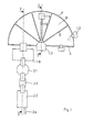
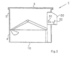
- Fig. 1 illustrates in a diagrammatic and simplified form the waste processing plant in a top view without the upper part
- the container 1 shown in Fig. 1 to 3 comprises a lower part 2 and an upper part 3
- the lower part 2 is shown in details on the Fig. 1, from which it is evident that the part has an outer wall 4, 5 shaped as a segment of a circle, in the embodiment shown as a semicircle.
- the upper part 3 is adapted to fit the outer walls of the lower part and is arranged on top thereof.
- the indicated outer walls 4,5 are preferably vertical.
- the upper part 3 forms the ceiling, whereby the container 1 is a closed container.
- the lower part 2 is divided into a plurality of tanks or vessels 9 open at the top and defined at the bottom by a floor 10 for the entire lower part.
- Each tank is provided with an inlet sluice opening 11 via the circular outer wall 4 for feeding a waste portion 12 to the tank.
- a digging means or an excavator 13 is arranged in a stationary manner in the centre of the circle and provided with a bucket arm 15 having a bucket 14.
- the arm 15 is movably arranged above any of the tanks by revolving about the centre of the circle, whereby it can operate above the upper edges of the individual partition walls 8.
- a control room 30 is shown provided with a control panel 31 for the excavator 13 and a seat 32 for an operator, who can see into the container 1 through a window in the control room 30.
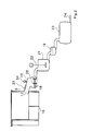
- the outer wall 5 is provided with an outlet opening 17 leading to a trough 18 having a stirring means 20 driven by a motor (not shown) and having an essentially horizontal axis.
- the trough 18 and the stirring means 20 form an intermediate mixer, to which the mixed waste is transferred subsequent to its removal from the container 1.
- the intermediate mixer 18, 20 has a relatively large capacity, e.g. from 5 to 20 m 3 . It may thus contain several admixed waste portions from the tanks 9, and thus forms a buffer portion able to contain at least the waste portions removed from five tanks 9. If one of these waste portions is particularly explosive, said portion is diluted in the intermediate mixer 18,20, whereby the danger of the resulting, pumpable and combustible waste exploding is limited.
- the trough 18 of the intermediate mixer is closed at the top by means of a plate 19 provided with a sight glass 33, and possibly a video camera 34, so that the operator may check the condition of the waste material.
- the waste is passed from the intermediate mixer 18,20 to an end mixer 21, in which it is ground by means of a power-driven stirring means 22, while a high shear is applied.
- the material is passed via a vibration filter 35 to a flow tank 23, from the outlet 24 of which the waste material being a pumpable and combustible mixture is passed to combustion nozzles in a incineration plant (not shown). If the viscosity in the end mixer is too high, liquid may be added, possibly a drained liquid phase from the waste portions.
- the container is made of steel and mounted on a concrete base (not shown).
- the inner faces of the individual tanks are preferably coated with a chemical inert material protecting the steel container against the reactive chemicals in the waste portions.
- the shovel or bucket means 13 is arranged in such a manner that the bucket 14 does not extend quite to the outer walls in the individual tanks 9.
- the upper part 3 preferably rests on the lower part 2 as a result of its weight, whereby it at a major explosion is lifted off of the lower part and thus removes the pressure.
- the upper part may also be attached to the lower part by means bolts (not shown) bursting when a predetermined pressure threshold is exceeded.
- Fig. 4 illustrates in a diagrammatic and simplified form a further embodiment of the container, seen in a top view without the upper part.
- this embodiment is selected, if more tanks than possible in the embodiment shown in Figs. 1 to 3 are desired.
- the parts in Fig. 4 have the same reference numerals as the corresponding parts in Figs. 1-3.
- the ground plan of the container is of a rectangle shape.
- the partition walls 8 of the lower part extend parallel with the short sides 25 of the rectangular.
- a travelling crane 26 is used instead of the excavator 13 of Figs. 1 to 3, said crane being slidable in the longitudinal direction of the rectangle on a track 27 parallel with the long side 28 of the rectangle.
- a plurality of tanks 9 are provided to receive the waste portions, and an outlet opening 17 is provided in a lateral wall 28, said opening passing the waste portions to the intermediate mixer 18, 19, 20, to the end mixer, and further to the flow tank 23.
- a waste processing plant receives a wide range of chemical wastes in solid, paste-like or liquid form, often as heterogeneous mixtures, on a continuous basis. Each type of waste is received in large or small portions, usually in closed containers, typically containing approximately 200 litres.
- Heterogeneous waste portions containing a liquid phase are drained.
- the resulting liquid phases are combined with the incoming liquid waste portions in a solvent setting tank, in which the pooled liquid phases and portions are allowed to stand, whereafter an equilibrium will be obtained, usually in such a manner that incompatible solvents separate into two or more phases.
- a non-polar phase in particular aromatic solvents
- a polar phase containing esters, ketones, alcohols and water is formed at the bottom.
- transition phases with or without a definite interface are also present.
- each individual compound is distributed in the separate phases in a ratio depending on the compatibility of the compound with the other constituents in the phase.
- each phase it is not necessary to know the exact composition of each phase, and for instance two fractions may be chosen, a polar and a non-polar phase, or three or more fractions from different levels may be selected.
- the desired number of fractions (I, II%) are selected and each fraction is accumulated in a separate reservoir.
- phase separation between the combined solvents is carried out in a receiver being filled continuously, each of the separated fractions is thus removed and transferred to its separate reservoir as new amounts of solvent is added to the receiver.
- the equilibrium between the phases is set within approximately one hour, which can be taken into account when dimensioning the receiver. It should, however, be assumed that it is not vital for the carrying out of the method according to the invention that a complete phase equilibrium is present prior to the removal of a solvent fraction.
- One container portion at a time of the solid or semi-solid (viscous) waste portions is fed into one of the tanks in the closed plant shown in Fig. 1-3.
- a test of its compatibility with one or more of the liquid fractions is made.
- said test is carried out by the operator, adding a small portion of the liquid fraction and observing the waste portion in the defined area, to which the liquid fraction has been added.
- the operator performs mixing movements in said area by means of the shovel or bucket means of the plant.
- the compatibility test is positive. If, however, the waste portion and the liquid fraction provide the material with a gritty, heterogeneous surface, the test is negative. If so, the operator repeats the compatibility test with another of the liquid fractions.
- mixing tests with two or more of the waste portion in the tanks may be performed followed by further combination and mixing of the waste portions in the tanks or the waste may be transferred in small portions directly to an intermediate mixer containing e.g. a total of 10 m 3 waste in form of a buffer portion.
- an intermediate mixer containing e.g. a total of 10 m 3 waste in form of a buffer portion.
- the processing in the intermediate mixer and the subsequent processing is carried out as described in EP patent No. 73 787 and shown in the Figure therein.
- the intermediate mixer may be a pawl or paddle mixer designed as a trough provided with one or more shafts having a plurality of radially projecting paddles or plates. Typically, the shafts may rotate at a speed of 20-25 rotations per minute.
- the waste material is processed in the intermediate mixer, additional solvent being added, if required, to obtain of suitable viscosity being determined visually. Usually, only addition of water as the additional solvent is required.
- the processing continues, until the waste material is sufficiently homogenized, said condition being determined visually, homogenous waste having a glossy surface, and a heterogeneous waste having a gritty surface.
- the buffer portion When the buffer portion is homogenized, a portion thereof, for instance of 2 m 3 is taken out of the intermediate mixer. This portion is transferred to a high speed mixer comprising a container provided with a stirring means with a vertical shaft, such as a dissolver.
- the circumferential speed of the stirring means is typically 20-30 m/sec.
- the stirring means in the high speed mixer comminutes any remaining solid lumps and dissolves or disperses these in the solvent. If necessary, additional solvent may be added, for instance water, to obtain the desired viscosity. It is, however, preferably that the necessary additions of solvent has already been carried out in the intermediate mixer.
- An essentially homogeneous mixture is obtained in form of a pumpable dispersion with a viscosity at 20°C of between 0.27 and 0.85 Pa.s, preferably between 0.45 and 0.70 Pa ⁇ s. This portion is transferred to a storage container through a filter.
- the materials accumulated in the filter may be recirculated to the process. By utilizing such a recirculation, the demand on the pumpable dispersion is decreased. A shorter stirring time is thus required in the high speed mixer.
- the pumpable dispersion may be atomized into a combustion furnace, e.g a cement kiln, through a nozzle.
- a combustion furnace e.g a cement kiln
- the use of a cement kiln is advantageous in that an alkaline environment with high temperatures is present so that any metals in the waste will be bound as oxides or collected in electro filters.
- each waste portion may be gradually passed on from the tanks of the plant, however, occasionally some portions cannot initially be mixed with the other portion to obtain a homogeneous mixture. Such portions can be "left", until a suitable waste portion being compatible therewith is received. Variations in the different liquid solvent fractions may also occur, for which reason the operator occasionally may test, if the difficult waste portion has obtained compatibility with one of the liquid solvent fractions present in the reservoirs at the time in question. In particularly difficult cases, it is possible to add a particularly suitable additional solvent, although this - naturally - should be avoided for economic reasons.
- the present example describes a practical, small scale test carried out in the course of two days.
- a conventional mortar mixer without mixer arms was used for the initial mixing and for the subsequent formation of a buffer portion.
- some bricks i.e. die-shaped stones of a size of approximately 10 x 10 x 10 cm 3 , were placed in the mortar mixer.
- the material was stirred in an open, bowl-shaped container by means of a drilling machine provided with a stirring propeller at high speed, approximately 1000 rotations per minute.
- Tests in the mortar mixer were carried out in the open air at 3-15°C.
- the final homogenizing was carried out at room temperature.
- the initial materials were stored in the open.
- the obtained dispersion samples were stored at room temperature, if not indicated otherwise.
- the dispersions prepared in the mortar mixer were stored in the open.
- a basic mixture were prepared by mixing 2 kg of distillation residue from paint distillation (sample 8), 200 g of synthetic resin waste (sample 2), 1 kg of hard resin waste (sample 4), 1 kg of solvent-containing sludge (sample 5), and about 2 litre of toluene.
- This mixture was processed in the mortar mixer with eight bricks (approx. 10 cm x 10 cm x 10 cm) for half an hour. One litre of water was then added, the mixture was stirred for yet half an hour. The resulting mixture was dark-grey going on black.
- sample 1 and sample 3 The mixture was built up by additional portions of distillation residues of 1 kg (sample 1 and sample 3) and glycol mixture (sample 6). Subsequent to yet another hour's mixing, a sample on 0.5 litre was taken out and shaken for 20 minutes by means of the drilling machine provided with a propeller at the top speed, 1000 rotations per minute. A homogenous, greyish black, viscous mass was obtained which did not display any phase separation.
- the order of the feeding of the individual waste materials was determined during the test on the basis of the evaluation of the material in the mortar mixer.
- the surface of the material is an essential feature, as a uniform colour and a high gloss is a sign of good compatibility between the mixed materials.
- a gritty surface structure indicates a limited compatibility.
- dispersion A + B 1 litre of dispersion A and 1 litre of dispersion B were mixed for 15 minutes under vigorous stirring to form the dispersion A + B.
- Dispersions A, B and A + B displayed no differences in appearance. On the surface and in particular at the edges, a very thin water layer was visible. After a seven-day period at room temperature, no changes were apparent, and specifically no phase separation. Dispersions were viscous having been left to settle for one day. The dispersion became liquid when slightly stirred. The main portions of the dispersions stored in the open were liquid and had a slightly foamlike surface produced by degassing of the air saturated dispersion. These samples did not display any phase dispersion.
- the initial materials and the dispersions were analyzed for determining important parameters, such as the calorific value, the water content, the ash content, the chlorine content, and the content of heavy metals.
- the analysis results obtained are stated above at the description of the individual samples, only the analysis results above the limit of detection being stated.
- the analysis results for the dispersions A, B, and A+B appear from Table 2 below.
- the calorific values for the obtained dispersions A and A+B 21.87 MJ/kg (approx. 5200 kcal/kg) and 19.4 MJ/kg (approx. 4600 kcal/kg), respectively, are within the range of the minimum requirement (20.9 MJ/kg or 5000 kcal/kg) for liquid fuel substitutes for use in the cement industry.
- the calorific value for methanol is approximately 5000 kcal/kg.
- the water contents in the prepared dispersions are uniform and between 20 and 22 per cent.
- the comparatively high ash content in the dispersions mainly comes from the high quantity of ash in sample 8 and 10.
- the content of PCB in the initial materials and in the dispersions is below 0.5 ppm.
- the chlorine content in the prepared dispersions is below 1%.
- the sulphur content of 1.7% in dispersion A, the 3.7% in dispersion B, and the 2.1 % in dispersion A+B is practically exclusively from the photochemical salts in sample 10.
- the content of heavy metals appears from Table 4. Moreover, the content of Hg, Se, Te, Tl and V were determined, said contents being below the limit of detection in all of the analyses, viz. Hg ⁇ 0.2 ppm, Se ⁇ 0.2 ppm, Te ⁇ 1 ppm, Tl ⁇ 0.2 ppm and V ⁇ 0.5 ppm.
- Example 2 The method described in Example 2 may be carried out on a large scale by initially using a mixer having volume of approximately 4 m 3 instead of the mortar mixer and by subsequently using a high speed mixer of approximately 2 m 3 provided with a mixing head having paddles rotating with a peripheral speed of 26 m/s and an engine power of approx. 92 kW (125 h.p.).
Landscapes
- Engineering & Computer Science (AREA)
- Chemical & Material Sciences (AREA)
- Environmental & Geological Engineering (AREA)
- General Chemical & Material Sciences (AREA)
- General Health & Medical Sciences (AREA)
- Toxicology (AREA)
- Health & Medical Sciences (AREA)
- Chemical Kinetics & Catalysis (AREA)
- Oil, Petroleum & Natural Gas (AREA)
- Organic Chemistry (AREA)
- Mechanical Engineering (AREA)
- General Engineering & Computer Science (AREA)
- Processing Of Solid Wastes (AREA)
- Fertilizers (AREA)
- Solid Fuels And Fuel-Associated Substances (AREA)
Claims (19)
- Verfahren zur Verarbeitung von flüssigen, festen und/oder viskosen problematischen, organischen, chemischen Abfällen zu deren Entsorgung, falls möglich unter Verwendung des Brennwerts des Abfalls, umfassend die folgenden Schritte:a) die verschiedenen Abfalltypen, umfassend flüssige Anteile, feste oder viskose Anteile und mehrphasige Anteile werden in großen oder kleinen separaten Anteilen gesammelt,b) die flüssigen Phasen werden von mehrphasigen Anteilen abgetrennt, um weitere flüssige Anteile bzw. feste oder viskose Anteile zu erhalten,c) die flüssigen Abfallanteile werden vereint, und das entstandene flüssige Gemisch wird zur Trennung in eine Anzahl von Fraktionen (I, II, ...) stehen gelassen, wobei jede Fraktion danach in einen Sammelbehälter transferiert wird,d) alle viskosen oder festen Abfallanteile werden einem Kompatibilitätstest unterzogen, um zu bestimmen, ob der Abfallanteil in einer der flüssigen Fraktionen löslich oder quellfähig ist, wobei die Kompatibilitätstests ausgeführt werden durch Zugeben einer kleinen Probe von flüssigen Fraktionen,e) die Abfallanteile, die Löslichkeit oder Quellfähigkeit mit einer der flüssigen Fraktionen aufweisen, bezeichnet als Abfalltyp (I, II, ...), werden mit einer Menge der Fraktion gemischt, wobei gewährleistet wird, daß ein bearbeitbares Gemisch erhalten wird, wodurch eine Anzahl von Gemischen erhalten wird, jeweils bezeichnet als die relevanten Gemischtypen (I, II, ...),f) die verschiedenen Gemische werden graduell während der weiteren Verarbeitung gemischt, falls erforderlich, nach vorangehenden Mischversuchen von Proben davon, und gegebenenfalls unter Zumischen von zusätzlicher Flüssigkeit, so daß als Ergebnis ein gemischter und bearbeitbarer Pufferanteil erhalten wird, wobei der Pufferanteil eine Kombination der Gemischtypen (I, II, ...) enthält, und wobei überschüssige Abfallanteile oder -gemische zum Mischen mit nachfolgenden Abfallanteilen oder -gemischen stehengelassen werden,g) der Pufferanteil oder ein Teil davon wird einer Zerkleinerung bei hoher Scherung unterzogen, um ein pumpfähiges brennbares Material zu bilden, das als ein Brennstoff verwendet werden kann.
- Verfahren nach Anspruch 1, dadurch gekennzeichnet, daß die viskosen oder festen Abfallanteile in einen geschlossenen, gasdichten Raum, der mit mehreren Tanks ausgestattet ist, eingebracht werden, wobei jeder Anteil bei Ankunft in einen separaten Tank eingebracht wird.
- Verfahren nach Anspruch 2, dadurch gekennzeichnet, daß es möglich ist, mittels eines von außerhalb des gasdichten Raums bedienbaren Schaufel- oder Eimermittels Material von einem Tank zu einem anderen zu transportieren, einfache Mischbewegungen in den einzelnen Tanks auszuführen, und weiterhin, daß mittels des Schaufel- oder Eimermittels Anteile zum Einlaß eines Mischmittels transportiert werden können, worin der Pufferanteil behandelt wird.
- Verfahren nach einem der vorhergehenden Ansprüche, dadurch gekennzeichnet, daß es bei Umgebungstemperatur ausgeführt wird.
- Verfahren nach einem der vorhergehenden Ansprüche, dadurch gekennzeichnet, daß zusätzliches Lösungsmittel, ausgewählt aus polaren organischen Lösungsmitteln, nicht-polaren organischen Lösungsmitteln und Wasser, zugegeben wird zuzur Verwendung in einem oder mehreren der nachfolgenden Schritte d) - g).1) dem vereinten Gemisch vor dem Stehenlassen davon gemäß Schritt c) von Anspruch 1,2) zu einer oder mehreren der beim Trennen des flüssigen Gemisches gebildeten Fraktionen (I, II, ...) und/oder3) als unabhängige Fraktionen
- Verfahren nach einem der vorhergehenden Ansprüche, dadurch gekennzeichnet, daß zu dem Pufferanteil ein feinkörniges Material zugegeben wird, wobei das Material eine Teilchengröße von im wesentlichen weniger als 60 µm hat.
- Verfahren nach Anspruch 6, dadurch gekennzeichnet, daß daß das feinkörnige Material ausgewählt wird aus Kohlestaub, Filterstaub, Celluloseabfall, feinkörnigem Kunststoffgranulat und Bentonit.
- Verfahren nach einem der vorhergehenden Ansprüche dadurch gekennzeichnet, daß der Pufferanteil in einer Mischvorrichtung verarbeitet wird, um eine Dispersion mit einem glatten, nicht-grießartigen Aussehen zu erhalten, wobei eine Probe davon zur Verarbeitung gemäß Schritt g) entnommen wird, wonach und gemäß den Schritten a) - f) zusätzliches Abfallmaterial zu dem Pufferanteil zugegeben wird und danach eine erneute Verarbeitung erfolgt, um die gewünschte Dispersion zu erhalten.
- Verfahren nach einem der vorhergehenden Ansprüche dadurch gekennzeichnet, daß eine pumpfähige Dispersion mit einer Viskosität von nicht mehr als 1,0 Pa·s bei 20°C hergestellt wird.
- Verfahren nach Anspruch 9, dadurch gekennzeichnet, daß die pumpfähige Dispersion eine Viskosität zwischen 0,27 und 0,85 Pa s bei 20°C hat.
- Anlage zur Verarbeitung von flüssigen, festen und/oder viskosen problematischen, organischen, chemischen Abfällen zu deren Entsorgung, falls möglich unter Verwendung des Brennwerts des Abfalls, umfassend:a) ein Mittel zum Sammeln der verschiedenen Abfalltypen, umfassend flüssige Anteile, feste oder viskose Anteile und mehrphasige Anteile in großen oder kleinen separaten Anteilen,b) ein Mittel zum Auftrennen der mehrphasigen Anteile, um weitere flüssige Anteile bzw. feste oder viskose Anteile zu erhalten,c1) ein Mittel zum Vereinen der flüssigen Abfallanteile und zum Halten des entstandenen flüssigen Gemisches, wenn diese zur Trennung in eine Anzahl von Fraktionen (I, II, ...) stehengelassen werden,c2) eine Anzahl von Sammelbehältern mit Mitteln zum Transportieren aller Fraktionen (I, II, ...) zu und aus ihrem Sammelbehälter,d) ein Mittel, um alle viskosen oder festen Abfallanteile einem Kompatibilitätstest zu unterziehen, um zu bestimmen, ob der Abfallanteil in einer der flüssigen Fraktionen löslich oder quellfähig ist, wobei die Kompatibilitätstests ausgeführt werden durch Zugeben einer kleinen Probe von flüssigen Fraktionen,e) ein Mittel zum Mischen derjeniger Abfallanteile, die Löslichkeit oder Quellfähigkeit mit einer der flüssigen Fraktionen aufweisen, bezeichnet als Abfalltyp (I, II, ...), mit einer Menge der Fraktion, wobei gewährleistet wird, daß ein bearbeitbares Gemisch erhalten wird, wodurch eine Anzahl von Gemischen erhalten wird, jeweils bezeichnet als die relevanten Gemischtypen (I, II, ...),f) ein Mittel zum Mischen der verschiedenen Gemische graduell während der weiteren Verarbeitung, falls erforderlich, nach vorangehenden Mischversuchen von Proben davon, und gegebenenfalls unter Zumischen von zusätzlicher Flüssigkeit, so daß als Ergebnis ein gemischter und bearbeitbarer Pufferanteil erhalten wird, wobei der Pufferanteil eine Kombination der Gemischtypen (I, II, ...) enthält, und wobei überschüssige Abfallanteile oder -gemische zum Mischen mit nachfolgenden Abfallanteilen oder -gemischen stehengelassen werden,g) ein Mittel zum Unterziehen des Pufferanteils oder eines Teils davon einer Zerkleinerung bei hoher Scherung, um ein pumpfähiges brennbares Material zu bilden, das als ein Brennstoff verwendet werden kann.
- Abfallverarbeitungsanlage nach Anspruch 11, dadurch gekennzeichnet,daß sie einen geschlossenen Behälter umfaßt, welcher aus einem Unterteil mit einem Boden und bevorzugt senkrechten Außenwänden und einem die Decke bildenden Oberteil gebildet ist, wobei das Oberteil an den Oberkanten der Außenwände angeordnet ist und darauf passend ausgelegt ist,daß das Unterteil durch Innentrennwände in mehrere Tanks oder Gefäße unterteilt ist, welche nach oben offen sind und durch die Außenwände des Unterteils begrenzt sind,daß im wesentlichen jeder Tank mit einer Schleusen-Einlaßöffnung durch eine Außenwand versehen ist, um dem Tank einen Abfallanteil zuzuführen,daß eine Auslaßöffnung durch eine Außenwand vorhanden ist,daß ein im Inneren des Behälters vorhandenes und von außen zu bedienendes Schaufel- oder Eimermittel zum Transport von Material aus den Abfallanteilen oberhalb der Trennwände zwischen den einzelnen Tanks und dem Auslaß vorgesehen ist.
- Abfallverarbeitungsanlage nach Anspruch 12, dadurch gekennzeichnet, daß eine Zwischenmischvorrichtung mit der Auslaßöffnung verbunden ist, und daß der Abfall von der Auslaßöffnung zum Einlaßende der Zwischenmischvorrichtung geführt wird.
- Abfallverarbeitungsanlage nach Anspruch 13, dadurch gekennzeichnet, daß die Kapazität der Zwischenmischvorrichtung relativ groß ist, typischerweise zwischen 5-20 m3, beispielsweise 10 m3, wodurch sie eine große Abfallmenge, die einen Pufferanteil bildet, enthalten kann, und daß sie als ein Trog mit einem Kraft-getriebenen Rührmittel ausgebildet ist.
- Abfallverarbeitungsanlage nach den Ansprüchen 13 und 14, dadurch gekennzeichnet, daß das Auslaßende der Zwischenmischvorrichtung mit einer Endmischvorrichtung, zu der das Abfallmaterial zum Zerkleinern geführt wird, verbunden ist, wobei die Endmischvorrichtung mit einem Kraft-getriebenen Rührmittel ausgestattet ist, welches das Abfallmaterial einer hohen Scherung unterzieht.
- Abfallverarbeitungsanlage nach einem der Ansprüche 12-15, dadurch gekennzeichnet, daß das Oberteil des Behälters durch sein Gewicht auf dem Unterteil gehalten ist.
- Abfallverarbeitungsanlage nach einem der Ansprüche 12-16, dadurch gekennzeichnet, daß der Behälter aus Stahl ist und gegebenenfalls auf der Innenseite des Unterteils mit einem chemisch beständigen Material beschichtet ist.
- Abfallverarbeitungsanlage nach einem der Ansprüche 12-17, dadurch gekennzeichnet, daß der Grundriß des Behälters als ein Kreisausschnitt gebildet ist und die Trennwände des Unterteils als Radien in dem Kreis verlaufen, und daß das Schaufel- oder Eimermittel ein Bagger ist, der im Kreismittelpunkt stationär angeordnet ist und mit einem Eimerarm, der einen Eimer aufweist, ausgestattet ist, wobei der Arm durch Drehen um den Kreismittelpunkt über jedem der Tanks positionierbar ist und ein maximale Reichweite hat, wobei der Eimer nicht vollständig an die Innenseite der kreisförmigen Außenwand stößt.
- Abfallverarbeitungsanlage nach einem der Ansprüche 12-17, dadurch gekennzeichnet, daß der Grundriß des Behälters rechteckig ist, die Trennwände des Unterteils parallel zu den kurzen Seiten des Rechtecks verlaufen, und daß das Schaufel- oder Eimermittel ein Laufkran ist, der in Längsrichtung des Rechtecks auf einer Laufbahn parallel zu den langen Seiten des Rechtecks beweglich ist.
Applications Claiming Priority (3)
| Application Number | Priority Date | Filing Date | Title |
|---|---|---|---|
| DK72195 | 1995-06-23 | ||
| DK72195A DK171956B1 (da) | 1995-06-23 | 1995-06-23 | Fremgangsmaade til behandling af problematisk organisk kemisk affald samt anlaeg til brug ved fremgangsmaaden |
| PCT/DK1996/000264 WO1997001064A1 (en) | 1995-06-23 | 1996-06-18 | A method of processing problematic, organic, chemical wastes, and a plant for carrying out the method |
Publications (2)
| Publication Number | Publication Date |
|---|---|
| EP0834041A1 EP0834041A1 (de) | 1998-04-08 |
| EP0834041B1 true EP0834041B1 (de) | 1999-03-24 |
Family
ID=8096780
Family Applications (1)
| Application Number | Title | Priority Date | Filing Date |
|---|---|---|---|
| EP96921905A Expired - Lifetime EP0834041B1 (de) | 1995-06-23 | 1996-06-18 | Verfahren zur entsorgung von problemabfaellen, organischen oder chemischen abfaellen und anlage zur durchfuehrung des verfahrens |
Country Status (8)
| Country | Link |
|---|---|
| US (1) | US5980592A (de) |
| EP (1) | EP0834041B1 (de) |
| AT (1) | ATE178132T1 (de) |
| AU (1) | AU6298296A (de) |
| DE (1) | DE69601877D1 (de) |
| DK (1) | DK171956B1 (de) |
| ES (1) | ES2130834T3 (de) |
| WO (1) | WO1997001064A1 (de) |
Families Citing this family (4)
| Publication number | Priority date | Publication date | Assignee | Title |
|---|---|---|---|---|
| US20030147797A1 (en) * | 2001-02-26 | 2003-08-07 | Basok Boris Iv. | Pulse energy transformation |
| WO2002102714A1 (en) * | 2001-06-19 | 2002-12-27 | Pulse, Llc. | Treatment of organic waste and sludge |
| US7128780B2 (en) * | 2001-10-05 | 2006-10-31 | E. I. Du Pont De Nemours And Company | Process for producing building materials from raw paint sludge |
| KR20190022889A (ko) * | 2017-05-26 | 2019-03-06 | 노벨리스 인크. | 디코팅 시스템에서의 사이클론 먼지의 단광을 위한 시스템 및 방법 |
Family Cites Families (13)
| Publication number | Priority date | Publication date | Assignee | Title |
|---|---|---|---|---|
| US3951849A (en) * | 1971-09-07 | 1976-04-20 | Basic Incorporated | Production of dispersions of fine powders |
| US4164396A (en) * | 1976-04-28 | 1979-08-14 | The General Engineering Company (Radcliffe) Limited | Production of combustible products from waste materials |
| US4133273A (en) * | 1978-01-26 | 1979-01-09 | International Mechanical Contractors, Inc. | System for the disposal of sludge, hazardous and other wastes |
| US4320709A (en) * | 1980-09-29 | 1982-03-23 | Pyro-Sciences, Inc. | Hazardous materials incineration system |
| DK459080A (da) * | 1980-10-29 | 1982-04-30 | B Faurholdt | Fremgangsmaade og anlaeg til forbraending af kemisk affald lagret i fade |
| NO150372C (no) * | 1981-03-06 | 1984-10-03 | Dentor En As | Fremgangsmaate ved destruksjon av problemavfall |
| US5191155A (en) * | 1987-03-14 | 1993-03-02 | Grillo-Werke Ag | Process for nonpolluting destruction of polychlorinated waste materials |
| US4715300A (en) * | 1987-04-27 | 1987-12-29 | Stauffer Chemical Company | Method of disposing of materials by dissolving in acid and then incinerating |
| DE3924312C2 (de) * | 1989-07-22 | 1994-06-09 | Gfr Aufbereitung Reststoffe | Verfahren und Vorrichtung zur Verwertung von Reststoffen, Lack- und Farbschlämmen |
| EP0439645A1 (de) * | 1990-01-30 | 1991-08-07 | Officine Metalmeccaniche Nova S.P.A. | Verfahren zur gesteuerten Zuführung von Stadt- und/oder Sondermüll in einer Verbrennungsanlage und Vorrichtung zur Durchführung des Verfahrens |
| GB9206718D0 (en) * | 1992-03-25 | 1992-05-13 | Collier Philip J | Apparatus for treating or processing waste |
| US5269234A (en) * | 1992-10-20 | 1993-12-14 | Continental Cement Company | Method for processing solid, Hazardous waste material for use as a fuel |
| FR2702488A1 (fr) * | 1993-03-10 | 1994-09-16 | Flamme Jean Luc | Procédé de fabrication d'un combustible, procédé de chauffage mettant en Óoeuvre ce combustible et brûleur adapté à la mise en Óoeuvre du procédé. |
-
1995
- 1995-06-23 DK DK72195A patent/DK171956B1/da not_active IP Right Cessation
-
1996
- 1996-06-18 AT AT96921905T patent/ATE178132T1/de not_active IP Right Cessation
- 1996-06-18 ES ES96921905T patent/ES2130834T3/es not_active Expired - Lifetime
- 1996-06-18 AU AU62982/96A patent/AU6298296A/en not_active Abandoned
- 1996-06-18 WO PCT/DK1996/000264 patent/WO1997001064A1/en not_active Ceased
- 1996-06-18 EP EP96921905A patent/EP0834041B1/de not_active Expired - Lifetime
- 1996-06-18 DE DE69601877T patent/DE69601877D1/de not_active Expired - Lifetime
- 1996-06-23 US US08/981,422 patent/US5980592A/en not_active Expired - Fee Related
Also Published As
| Publication number | Publication date |
|---|---|
| AU6298296A (en) | 1997-01-22 |
| WO1997001064A1 (en) | 1997-01-09 |
| DK72195A (da) | 1996-12-24 |
| US5980592A (en) | 1999-11-09 |
| ATE178132T1 (de) | 1999-04-15 |
| DE69601877D1 (de) | 1999-04-29 |
| ES2130834T3 (es) | 1999-07-01 |
| DK171956B1 (da) | 1997-08-25 |
| EP0834041A1 (de) | 1998-04-08 |
Similar Documents
| Publication | Publication Date | Title |
|---|---|---|
| Pinasseau et al. | Best available techniques (BAT) reference document for waste treatment industrial emissions directive 2010/75/EU (integrated pollution prevention and control) | |
| EP0834041B1 (de) | Verfahren zur entsorgung von problemabfaellen, organischen oder chemischen abfaellen und anlage zur durchfuehrung des verfahrens | |
| EP1109633B1 (de) | Verfahren und anlage zum vorbehandeln und aufbereiten von kommunalen und industriellen abfällen zur herstellung von verwendbaren produkten | |
| KR101780672B1 (ko) | 분리형 세척수단을 포함하는 오염토양 정화장치 및 정화방법 | |
| UA55449C2 (uk) | Спосіб холодної переробки міського сміття і/або стічних вод в інертні матеріали та установка для його здійснення | |
| JP5110700B2 (ja) | 可燃性廃棄物の燃料化システム及び燃料化方法 | |
| CN1887762A (zh) | 固体废物浆渣新型处理方法 | |
| KR19990076618A (ko) | 폐기혼합물의분리법 | |
| JPH0237395B2 (de) | ||
| CN108203218A (zh) | 一种含油污泥的无害化处理工艺 | |
| JP5110699B2 (ja) | 可燃性廃棄物の燃料化システム及び燃料化方法 | |
| JPH0839099A (ja) | 含油廃棄物の処理法とそれに用いる廃棄物処理装置 | |
| US6125774A (en) | Industrial waste combustion process | |
| JP3094400B2 (ja) | 産業廃棄物混合燃料の製造方法および産業廃棄物の再利用方 | |
| JP3873223B2 (ja) | 煤塵中の重金属溶出防止方法 | |
| JP3235949U (ja) | 廃油含浸廃材チップからなる複合燃料の製造装置 | |
| EP0073787B1 (de) | Verfahren zur vernichtung von problemabfällen | |
| WO1990011144A1 (en) | Elimination of and beneficial use of harmful wastes | |
| Sudell | Evaluation of the BEST™ solvent extraction sludge treatment technology twenty-tour hour test | |
| Ghosh et al. | Pre-processing of Wastes into AFRs | |
| Jones | The BEST® solvent extraction process treatment of soil, sediment, and sludges | |
| McDonagh et al. | Handling and disposal of oily waste from oil spills at sea | |
| Amsoneit | A centralized hazardous waste treatment plant: The facilities of the ZVSMM at Schwabach as an example | |
| CN118221327A (zh) | 燃煤电站协同油泥减量化处理的系统及方法 | |
| Ayala | Used Oil Derived Fuel Utilization for the Production of Portland Cement |
Legal Events
| Date | Code | Title | Description |
|---|---|---|---|
| PUAI | Public reference made under article 153(3) epc to a published international application that has entered the european phase |
Free format text: ORIGINAL CODE: 0009012 |
|
| 17P | Request for examination filed |
Effective date: 19971216 |
|
| AK | Designated contracting states |
Kind code of ref document: A1 Designated state(s): AT BE CH DE DK ES FI FR GB GR IE IT LI LU NL PT SE |
|
| GRAG | Despatch of communication of intention to grant |
Free format text: ORIGINAL CODE: EPIDOS AGRA |
|
| 17Q | First examination report despatched |
Effective date: 19980525 |
|
| GRAG | Despatch of communication of intention to grant |
Free format text: ORIGINAL CODE: EPIDOS AGRA |
|
| GRAH | Despatch of communication of intention to grant a patent |
Free format text: ORIGINAL CODE: EPIDOS IGRA |
|
| GRAH | Despatch of communication of intention to grant a patent |
Free format text: ORIGINAL CODE: EPIDOS IGRA |
|
| GRAA | (expected) grant |
Free format text: ORIGINAL CODE: 0009210 |
|
| AK | Designated contracting states |
Kind code of ref document: B1 Designated state(s): AT BE CH DE DK ES FI FR GB GR IE IT LI LU NL PT SE |
|
| PG25 | Lapsed in a contracting state [announced via postgrant information from national office to epo] |
Ref country code: SE Free format text: THE PATENT HAS BEEN ANNULLED BY A DECISION OF A NATIONAL AUTHORITY Effective date: 19990324 Ref country code: NL Free format text: LAPSE BECAUSE OF FAILURE TO SUBMIT A TRANSLATION OF THE DESCRIPTION OR TO PAY THE FEE WITHIN THE PRESCRIBED TIME-LIMIT Effective date: 19990324 Ref country code: LI Free format text: LAPSE BECAUSE OF FAILURE TO SUBMIT A TRANSLATION OF THE DESCRIPTION OR TO PAY THE FEE WITHIN THE PRESCRIBED TIME-LIMIT Effective date: 19990324 Ref country code: IT Free format text: LAPSE BECAUSE OF FAILURE TO SUBMIT A TRANSLATION OF THE DESCRIPTION OR TO PAY THE FEE WITHIN THE PRESCRIBED TIME-LIMIT;WARNING: LAPSES OF ITALIAN PATENTS WITH EFFECTIVE DATE BEFORE 2007 MAY HAVE OCCURRED AT ANY TIME BEFORE 2007. THE CORRECT EFFECTIVE DATE MAY BE DIFFERENT FROM THE ONE RECORDED. Effective date: 19990324 Ref country code: GR Free format text: LAPSE BECAUSE OF NON-PAYMENT OF DUE FEES Effective date: 19990324 Ref country code: FR Free format text: LAPSE BECAUSE OF FAILURE TO SUBMIT A TRANSLATION OF THE DESCRIPTION OR TO PAY THE FEE WITHIN THE PRESCRIBED TIME-LIMIT Effective date: 19990324 Ref country code: FI Free format text: LAPSE BECAUSE OF NON-PAYMENT OF DUE FEES Effective date: 19990324 Ref country code: CH Free format text: LAPSE BECAUSE OF FAILURE TO SUBMIT A TRANSLATION OF THE DESCRIPTION OR TO PAY THE FEE WITHIN THE PRESCRIBED TIME-LIMIT Effective date: 19990324 Ref country code: BE Free format text: LAPSE BECAUSE OF FAILURE TO SUBMIT A TRANSLATION OF THE DESCRIPTION OR TO PAY THE FEE WITHIN THE PRESCRIBED TIME-LIMIT Effective date: 19990324 Ref country code: AT Free format text: LAPSE BECAUSE OF FAILURE TO SUBMIT A TRANSLATION OF THE DESCRIPTION OR TO PAY THE FEE WITHIN THE PRESCRIBED TIME-LIMIT Effective date: 19990324 |
|
| REF | Corresponds to: |
Ref document number: 178132 Country of ref document: AT Date of ref document: 19990415 Kind code of ref document: T |
|
| REG | Reference to a national code |
Ref country code: CH Ref legal event code: EP |
|
| REG | Reference to a national code |
Ref country code: IE Ref legal event code: FG4D |
|
| REF | Corresponds to: |
Ref document number: 69601877 Country of ref document: DE Date of ref document: 19990429 |
|
| PG25 | Lapsed in a contracting state [announced via postgrant information from national office to epo] |
Ref country code: LU Free format text: LAPSE BECAUSE OF NON-PAYMENT OF DUE FEES Effective date: 19990618 Ref country code: IE Free format text: LAPSE BECAUSE OF NON-PAYMENT OF DUE FEES Effective date: 19990618 |
|
| PG25 | Lapsed in a contracting state [announced via postgrant information from national office to epo] |
Ref country code: PT Free format text: LAPSE BECAUSE OF FAILURE TO SUBMIT A TRANSLATION OF THE DESCRIPTION OR TO PAY THE FEE WITHIN THE PRESCRIBED TIME-LIMIT Effective date: 19990624 Ref country code: DK Free format text: LAPSE BECAUSE OF FAILURE TO SUBMIT A TRANSLATION OF THE DESCRIPTION OR TO PAY THE FEE WITHIN THE PRESCRIBED TIME-LIMIT Effective date: 19990624 |
|
| PG25 | Lapsed in a contracting state [announced via postgrant information from national office to epo] |
Ref country code: DE Free format text: LAPSE BECAUSE OF FAILURE TO SUBMIT A TRANSLATION OF THE DESCRIPTION OR TO PAY THE FEE WITHIN THE PRESCRIBED TIME-LIMIT Effective date: 19990625 |
|
| REG | Reference to a national code |
Ref country code: ES Ref legal event code: FG2A Ref document number: 2130834 Country of ref document: ES Kind code of ref document: T3 |
|
| EN | Fr: translation not filed | ||
| NLV1 | Nl: lapsed or annulled due to failure to fulfill the requirements of art. 29p and 29m of the patents act | ||
| REG | Reference to a national code |
Ref country code: CH Ref legal event code: PL |
|
| PLBE | No opposition filed within time limit |
Free format text: ORIGINAL CODE: 0009261 |
|
| STAA | Information on the status of an ep patent application or granted ep patent |
Free format text: STATUS: NO OPPOSITION FILED WITHIN TIME LIMIT |
|
| 26N | No opposition filed | ||
| REG | Reference to a national code |
Ref country code: IE Ref legal event code: MM4A |
|
| PGFP | Annual fee paid to national office [announced via postgrant information from national office to epo] |
Ref country code: GB Payment date: 20010607 Year of fee payment: 6 |
|
| PGFP | Annual fee paid to national office [announced via postgrant information from national office to epo] |
Ref country code: ES Payment date: 20010621 Year of fee payment: 6 |
|
| REG | Reference to a national code |
Ref country code: GB Ref legal event code: IF02 |
|
| PG25 | Lapsed in a contracting state [announced via postgrant information from national office to epo] |
Ref country code: GB Free format text: LAPSE BECAUSE OF NON-PAYMENT OF DUE FEES Effective date: 20020618 |
|
| PG25 | Lapsed in a contracting state [announced via postgrant information from national office to epo] |
Ref country code: ES Free format text: LAPSE BECAUSE OF NON-PAYMENT OF DUE FEES Effective date: 20020619 |
|
| REG | Reference to a national code |
Ref country code: ES Ref legal event code: PC2A |
|
| GBPC | Gb: european patent ceased through non-payment of renewal fee |
Effective date: 20020618 |
|
| REG | Reference to a national code |
Ref country code: ES Ref legal event code: FD2A Effective date: 20030711 |