EP0833028B1 - Butée d'arrêt de glissière de guidage pour arrêt de fenêtre ou de porte - Google Patents
Butée d'arrêt de glissière de guidage pour arrêt de fenêtre ou de porte Download PDFInfo
- Publication number
- EP0833028B1 EP0833028B1 EP97114306A EP97114306A EP0833028B1 EP 0833028 B1 EP0833028 B1 EP 0833028B1 EP 97114306 A EP97114306 A EP 97114306A EP 97114306 A EP97114306 A EP 97114306A EP 0833028 B1 EP0833028 B1 EP 0833028B1
- Authority
- EP
- European Patent Office
- Prior art keywords
- window
- fork
- slot
- sliding guide
- stop member
- Prior art date
- Legal status (The legal status is an assumption and is not a legal conclusion. Google has not performed a legal analysis and makes no representation as to the accuracy of the status listed.)
- Expired - Lifetime
Links
Images


Classifications
-
- E—FIXED CONSTRUCTIONS
- E05—LOCKS; KEYS; WINDOW OR DOOR FITTINGS; SAFES
- E05C—BOLTS OR FASTENING DEVICES FOR WINGS, SPECIALLY FOR DOORS OR WINDOWS
- E05C17/00—Devices for holding wings open; Devices for limiting opening of wings or for holding wings open by a movable member extending between frame and wing; Braking devices, stops or buffers, combined therewith
- E05C17/02—Devices for holding wings open; Devices for limiting opening of wings or for holding wings open by a movable member extending between frame and wing; Braking devices, stops or buffers, combined therewith by mechanical means
- E05C17/04—Devices for holding wings open; Devices for limiting opening of wings or for holding wings open by a movable member extending between frame and wing; Braking devices, stops or buffers, combined therewith by mechanical means with a movable bar or equivalent member extending between frame and wing
- E05C17/12—Devices for holding wings open; Devices for limiting opening of wings or for holding wings open by a movable member extending between frame and wing; Braking devices, stops or buffers, combined therewith by mechanical means with a movable bar or equivalent member extending between frame and wing consisting of a single rod
- E05C17/24—Devices for holding wings open; Devices for limiting opening of wings or for holding wings open by a movable member extending between frame and wing; Braking devices, stops or buffers, combined therewith by mechanical means with a movable bar or equivalent member extending between frame and wing consisting of a single rod pivoted at one end, and with the other end running along a guide member
- E05C17/28—Devices for holding wings open; Devices for limiting opening of wings or for holding wings open by a movable member extending between frame and wing; Braking devices, stops or buffers, combined therewith by mechanical means with a movable bar or equivalent member extending between frame and wing consisting of a single rod pivoted at one end, and with the other end running along a guide member with braking, clamping or securing means at the connection to the guide member
-
- E—FIXED CONSTRUCTIONS
- E05—LOCKS; KEYS; WINDOW OR DOOR FITTINGS; SAFES
- E05D—HINGES OR SUSPENSION DEVICES FOR DOORS, WINDOWS OR WINGS
- E05D15/00—Suspension arrangements for wings
- E05D15/48—Suspension arrangements for wings allowing alternative movements
- E05D15/52—Suspension arrangements for wings allowing alternative movements for opening about a vertical as well as a horizontal axis
- E05D15/5202—Suspension arrangements for wings allowing alternative movements for opening about a vertical as well as a horizontal axis with non-horizontally extending checks
Definitions
- the invention relates to a window or a door with an opening limiter the preamble of claim 1.
- Opening limiters equipped with such sliding guide stop pieces are has been known for a long time and in many different designs. you will be so-called swing-wing windows and doors to limit the Opening angle of their wings about the lateral vertical axis also assigned, like windows with bottom-hung sashes, which are not exclusively but mainly as so-called skylight windows are used.
- Has sliding guide stopper in which an elongated hole for guiding a Head bolt is pivotally received.
- the sliding guide stop consists essentially of a housing and a limited slidably guided fork body, which has a passage for either releases or closes the head bolt.
- the fork body under a cover of the elongated hole guide of the head bolt Housing by a spring in a position closing the openings acted upon by a locking mechanism with a rotary bolt Displacement of the fork body can be opened.
- the headed bolt lies there in the open end position of the window or door leaf on one by the Limit stop end formed immediately next to that by the Fork body formed closure of the opening for the head bolt.
- the nature of the opening restrictor according to FR-A 2115731 an inclination of the tilting arm and / or safety arm does not. Also is the construction with a housing, a matching lid and the spring-loaded fork body is relatively complex and complicated Manufacturing.
- the invention is therefore based on the object of creating a window with one to provide a simply constructed opening limiter, which on the one hand easily for each of the three different types of installation mentioned between The sash and frame of windows and doors are suitable, but at the same time also has the simplest possible structure.
- Opening limiter is basically provided so that their Move the stop arms on the horizontal level between the sash and frame
- these opening limiters can be installed in the bottom hung windows be that they lie between the sash and frame and their Move the raising and / or securing arms on vertical levels.
- bottom-hung windows also possible so that they with their Extension arms and / or safety arms on the arms removed from the tilt axis - Attack the upper - horizontal frame and wing spars.
- the opening limiter While maintaining a structurally compact design of the sliding guide stop its functional reliability in the respective state of use the opening limiter optimized because in the transition area between the Elongated hole of the stop piece and the fork slot of the fork body one positive interlocking is present, which is undesirable and unintentional disengagement of the extension and / or securing arm protruding head bolt from the stop piece.
- the closest limit to the fork legs Bulge can according to the invention on the fork body at a elastically evasive tongue are formed, the free end of a hook facing the filler with a Cross flank and a sloping flank is.
- This configuration ensures that after assembly the sliding guide stop piece between the Stop piece itself and the fork body housed Filler piece at least after a few displacements of the Fork piece automatically then in its proper Functional position comes when it is during the Assembly process is not yet in this proper Functional position is.
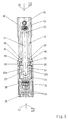
- a window 1 is shown in a vertical section in FIG. 1 shown, which consists of a frame 2 and a wing 3rd consists, for example, of light metal hollow profiles are manufactured.
- Wing 3 movably suspended on frame 2.
- FIG. 1 A window similar to FIG. 1 is also the one in FIG See drawing. Different in both figures Drawing only the opening limiter 5 installed.
- the Opening limiter 5 At the bottom-hung window design according to Fig. 1 has the Opening limiter 5 its installation location in the area between an upright leg of the frame 2 and the adjacent, upright leg of the wing 3.
- a mounting base 6th of the opening limiter 5 on the inside of an upright Leg of the frame 2 is mounted stationary.
- an issuing and / or Ficherarm 8 at its upper end on a vertical plane pivotally suspended one at its lower end Head bolt 9 per se known embodiment carries.
- This Head pin 9 acts with a sliding guide stop piece 10 together, which on an upright spar concerned of the frame 2 adjacent upright spar of the wing 3 is mounted.
- the head pin 9 at the front end of the exhibiting and / or Securing arm 8 therefore also engages in the sliding guide stop piece 10 on the upper horizontal spar of the wing 3 on.
- the raising and securing arm 8 do not move on a horizontal plane. Rather, he will due to the tilting of the wing 3 around its lower Tilt axis 4 in the length range between the journal 7 and the head pin 9 elastically bent, because namely upper horizontal spar of wing 3 over the possible Tilt angle along an arc around the tilt axis 4 relocated, so it sinks into the room all the more, than its tilt angle with respect to the frame 2 enlarged.
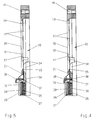
- the best and simplest is the actual one Slideway stop piece 10 as a molded part from a rigid Material, e.g. Die-cast zinc or brass, manufacture because then for him in a single operation its practical use necessary shapes can be conveyed.
- a rigid Material e.g. Die-cast zinc or brass
- an elongated hole 11 is formed, which is in the direction of a longitudinal median plane 12-12 extends to which the sliding guide stopper 10 itself is designed symmetrically.
- the slot 11 has one Limit stop end 13, with each of the shaft of the Head bolt 9 of the raising and / or securing arm 8 in System occurs when the window or door leaf 3 its predetermined opening end position reached.
- FIGS. 4 to 6, 8, 11 and 13 it can be seen that the passage extension 14 of the Elongated holes 11 in the sliding guide stop 10 with their upper opening edges 15 on another, namely one is lower level than the upper longitudinal edges 16 of the elongated hole 11 itself.
- the transition from the elongated hole 11 into the Passage extension 14 is thus quasi like a stage 17 designed.
- At the end sections facing level 17 18 of the flanks flanking the slot 11 closes so to a certain extent on the sliding guide stop piece 10 Trough, which there also through step-like to the outside remote areas 19 is limited.
- a special fork body 21 is added, which in Direction to the limit stop end 13 of the elongated hole is open, and in such a way that its through the two Fork legs 22a and 22b laterally delimited fork slot 23 one of the elongated hole 11 in the sliding guide stop piece 10 has the corresponding width.
- the fork body 21 is with the free ends of its two fork legs 22a and 22b End sections 18 of the slot 11 in the sliding guide stop 10 flanking longitudinal strips or the there located steps 17 which extend in the vertical direction, as well as the areas 19 that are stepped sideways turned to.
- the Fork body 21 designed so that the upper edges of his Fork slot 23 are at the same level as the upper ones Longitudinal edges 16 of the elongated hole 11.
- connection of the fork body 21 with the sliding guide stop 10 is provided to be longitudinally displaceable to a limited extent. I.e. the fork body 21 can be relative to the sliding guide stop 10 between that of FIGS. 3 to 5 and 11 respectively and 12 apparent clutch position and that of FIG. 13 and 14 removable longitudinal position. in the the former case is the passage extension 14 to Slotted hole 11 in the sliding guide connector 10 or locked. In the other case, however, it is released.
- the fork body 21 also be a To manufacture molded part so that it with a single Operation its final and operational shape receives.
- it should have a limited elasticity Material, for example by injection molding Hard plastic must be made available so that it can focus on simplest way, especially in the manner of a snap / snap connection, can be attached to the sliding guide stop piece 10.
- Hard plastic must be made available so that it can focus on simplest way, especially in the manner of a snap / snap connection, can be attached to the sliding guide stop piece 10.
- the fork body 21 first in the position shown in FIGS. 6 and 7 on Apply the sliding guide stop piece 10. Then he lets himself go brought about by a unilaterally applied pressure elastic deformation from the position according to FIGS. 6 and 7 bring into the connection position according to FIGS. 8 and 9.
- An important training measure is also that the fork body 21 on the sliding guide stopper 10 constantly in the direction of its closed position (see FIGS. 3 to 5 and 11 and 12 of the drawing) with an elastic Preload is supported.
- This can, as again from the Fig. 3 to 5 and 11 and 12 emerges by housing a filler 26 from an elastically compliant Material can be reached in a cavity 27, which between the sliding guide connector 10 and the Fork body 21 is limited.
- the filler 26 can advantageously are formed by a helical compression spring.
- An elastomer block can also be used as well use which is a correspondingly large and durable Elastic behavior shows up.
- the sloping edge 34 is oriented on the hook 32 so that this when moving the fork body 21 in the direction of its closed position according to FIGS. 3 to 5 on the in Cavity 27 received filler 26 can slide away (see e.g. Figs. 8 and 11) until the transverse flank 33 snaps back end of the filler 26 (Fig. 11).
- Filler 26 and fork body 21 thereby take automatically their proper functional position to each other. I.e. by Pushing the fork body 21 back into its release or Decoupling position (Fig. 13 and 14), the filler 26th (Helical compression spring / elastomulti block) properly biased.
- Both the fork body 21 and namely the sliding guide stopper 10 contain each a profile passage 35 directed transversely to its main plane and 36.
- the profile passage 35 is in the Fork body 21 and has by the operating handle 29th protruding tongue 31 around an approximately U-shaped contour or U-shaped profile, which in each case clearly from FIG. 10, 12 and 14 can be seen.
- the profile passage 36 in the sliding guide stop 10 essentially one Rectangular contour, in which areas a nose 37 protrudes.
- the sliding guide stop 10 for the purpose of creating an installation possibility in undercut profiled grooves on wing 3 of windows or doors 1 have base parts 40 formed on the longitudinal side with which he can get into the undercut areas of these grooves can be inserted.
- base parts 40 formed on the longitudinal side with which he can get into the undercut areas of these grooves can be inserted.
- a suitable clamping or Screw in the punch screw is merely a definition within these profile grooves necessary in a threaded hole 41 or even in several threaded holes 41 of the sliding guide stop piece 10 a suitable clamping or Screw in the punch screw.
Landscapes
- Engineering & Computer Science (AREA)
- Mechanical Engineering (AREA)
- Wing Frames And Configurations (AREA)
- Window Of Vehicle (AREA)
- Closing And Opening Devices For Wings, And Checks For Wings (AREA)
Claims (6)
- Elément d'arrêt coulissant (10) pour limitateur d'ouverture (5) de battants de fenêtres et portes (3), notamment pour bras d'orientation de battants à charnière inférieure et / ou bras de sécurité, disposés de manière à pouvoir au moins coulisser le long d'une traverse dormante (2) d'une fenêtre (1) ou d'une porte.caractérisé en ce quepourvu d'un trou longitudinal (11),dans lequel un pivot (9) situé à l'extrémité libre du bras d'orientation et / ou de sécurité (8) s'insère de manière à pouvoir pivoter, coulisser et s'incliner,le pivot (9) du bras d'orientation et / ou de sécurité (8) pouvant s'engrener ou se désengrener avec l'élément d'arrêt coulissant en un point éloigné de la butée de limitation du trou longitudinal (7),une extension (14) de passage de la tête du pivot (9) est prévue à l'extrémité de l'élément d'arrêt en contact avec la butée de limitation (13) du trou longitudinal (11), ou proche de celle-ci.Cette extension de passage (14) peut être débloquée ou bloquée au moyen d'un corps en forme de fourche capable de coulisser de manière limitée dans le sens longitudinal de l'élément d'arrêt (10) et dont l'ouverture est orientée vers la butée de limitation (13),Le corps en forme de fourche (21) en contact avec l'élément d'arrêt (10) est toujours soutenu par une prétension élastique (26) dans le sens de sa position de fermeture.
- Elément d'arrêt coulissant (10) selon la revendication 1, caractérisé en ce queLa largeur de la rainure de la fourche (23) du corps en forme de fourche (21) correspond à celle du trou longitudinal (11) de l'élément d'arrêt (10),Les bords d'ouverture supérieurs (15) de l'extension de passage (14) du trou longitudinal (11) de l'élément d'arrêt (10) sont plus bas que les bords longitudinaux supérieurs (16) du trou longitudinal (11),Au moins les montants de la fourche (22a, 22b) du corps en forme de fourche (21) sont reçus dans un enfoncement de l'élément d'arrêt (10), dont la profondeur correspond à la distance entre le plan des bords d'ouverture supérieurs (15) de l'extension de passage (14à et le plan des bords longitudinaux supérieurs (16) du trou longitudinal (11)Au dessus de l'extension de passage (14), les bords longitudinaux (16) du trou longitudinal (11) sont progressivement (19) décalés et élargis vers l'extérieurLes extrémités libres des montants de la fourche (22a, 22b) du corps en forme de fourche (21) peuvent être insérées eentre les cames finales pour ainsi atteindre une position de bloquage au-dessus de l'extension de passge (14).
- Elément d'arrêt coulissant (10) selon les revendications 1 ou 2,
caractérisé en ce que
il a été conçu comme une moulure à partir d'un matériau rigide comme du zink ou du laiton coulé sous pression,le corps en forme de fourche (21) étant également une moulure, mais à partir d'un matériau à élasticité limitée, comme du plastique coulé par injection.Les deux moulures présentent des contre-dépouilles (24, 25) qui s'étendent dans le sens longitudinal et se complètent l'une l'autre,grâce à ces contre-dépouilles, les moulures peuvent s'engrener l'une dans l'autre avec translation limitée, uniquement sous la forme d'un raccordement par encliquetement / crantage. - élément d'arrêt coulissant (10) selon l'une ou l'autre des revendications 1 à 3,
caractérisé en ce queaux points de raccordement avec ses montants de fourche (22a, 22b, le corps en forme de fourche (21) est surélevé, formant une poignée de manipulation (29) ainsi qu'une indentation (28) sur la face inférieure.l'élément d'arrêt (10) présente une indentation (30) près de son extension de passage (14),les indentations (28,30) délimitent ensemble un espace creux recevant une pièce de remplissage (26) constituée d'un matériau élastique, comme par exemple un ressort cylindrique de compression ou un bloc élastomère, en guise de membre de placement et de soutien pour le corps en forme de fourche (21). - Elément d'arrêt coulissant (10) selon l'une ou l'autre des revendications 1 à 4,
caractérisé en ce que
dans le corps en forme de fourche (21), la limitation de l'indentation (28) la plus proche des montants de la fourche (22a, 22b) est en contact avec une languette (31) élastique et déviable dont l'extrémité libre forme un crochet orienté vers la pièce de remplissage (26), avec un flanc transversal (33) et un flanc diagonal (34). - Elément d'arrêt coulissant (10) selon l'une ou l'autre des revendications 1 à 5,
caractérisé en ce que
le corps en forme de fourche (21) et l'élément d'arrêt (10) sont pourvus d'une section de passage profilée (35 et 36) orientée transversalement vers leur plan principal,ces sections de passage profilées (35 et 36) se recouvrent l'une l'autre lorsque le corps en forme de fourche (21) est en position de bloquage - déplacement,un corps de verrouillage (38) approprié peut être inséré de manière amovible dans les sections de passage profilées (35, 36) se recouvrant l'une l'autre.
Applications Claiming Priority (2)
| Application Number | Priority Date | Filing Date | Title |
|---|---|---|---|
| DE29616844U DE29616844U1 (de) | 1996-09-27 | 1996-09-27 | Gleitführungs-Anschlagstück für Öffnungsbegrenzer von Fenster- und Türflügeln |
| DE29616844U | 1996-09-27 |
Publications (2)
| Publication Number | Publication Date |
|---|---|
| EP0833028A1 EP0833028A1 (fr) | 1998-04-01 |
| EP0833028B1 true EP0833028B1 (fr) | 2000-11-08 |
Family
ID=8029819
Family Applications (1)
| Application Number | Title | Priority Date | Filing Date |
|---|---|---|---|
| EP97114306A Expired - Lifetime EP0833028B1 (fr) | 1996-09-27 | 1997-08-19 | Butée d'arrêt de glissière de guidage pour arrêt de fenêtre ou de porte |
Country Status (3)
| Country | Link |
|---|---|
| EP (1) | EP0833028B1 (fr) |
| AT (1) | ATE197486T1 (fr) |
| DE (2) | DE29616844U1 (fr) |
Cited By (1)
| Publication number | Priority date | Publication date | Assignee | Title |
|---|---|---|---|---|
| DE202024101127U1 (de) | 2024-03-07 | 2024-04-02 | Siegenia-Aubi Kg | Fenster- oder Türflügel mit Öffnungsbegrenzer |
Families Citing this family (5)
| Publication number | Priority date | Publication date | Assignee | Title |
|---|---|---|---|---|
| GB2421267A (en) * | 2004-12-17 | 2006-06-21 | Clearview Windows Ltd | A sash window tilt restrictor arm arrangement |
| ITBO20060897A1 (it) * | 2006-12-29 | 2008-06-30 | Gsg Int Spa | Infisso con apertura a vasistas. |
| DE102007021979B3 (de) * | 2007-05-10 | 2008-08-07 | Hautau Gmbh | Gleitvorrichtung für Schiebe- oder Abstellschiebeflügel |
| DE202016001421U1 (de) * | 2016-03-07 | 2016-04-22 | Siegenia-Aubi Kg | Ausstellvorrichtung |
| CN110128003B (zh) * | 2019-06-18 | 2023-11-14 | 新沂市引河石英材料有限公司 | 一种自清洁的高纯熔融石英加工用除杂装置 |
Family Cites Families (5)
| Publication number | Priority date | Publication date | Assignee | Title |
|---|---|---|---|---|
| FR1227781A (fr) * | 1959-06-18 | 1960-08-24 | Dispositif de sécurité pour fenêtre basculante | |
| FR2115731A5 (fr) * | 1970-11-27 | 1972-07-07 | Ferco Usine Ferrures | |
| FR2456199A1 (fr) * | 1979-05-11 | 1980-12-05 | Ferco Int Usine Ferrures | Dispositif de verrouillage de compas decrochable de fenetre, porte ou analogue |
| FR2632344B1 (fr) * | 1988-06-02 | 1990-08-17 | Ferco Int Usine Ferrures | Compas entrebailleur pour fenetre s'ouvrant a l'italienne, a l'australienne, pivotante ou a ouvertures analogues |
| DE9403993U1 (de) * | 1994-03-10 | 1994-05-05 | Roto Frank Ag | Dachfenster |
-
1996
- 1996-09-27 DE DE29616844U patent/DE29616844U1/de not_active Expired - Lifetime
-
1997
- 1997-08-19 EP EP97114306A patent/EP0833028B1/fr not_active Expired - Lifetime
- 1997-08-19 DE DE59702597T patent/DE59702597D1/de not_active Expired - Lifetime
- 1997-08-19 AT AT97114306T patent/ATE197486T1/de not_active IP Right Cessation
Cited By (1)
| Publication number | Priority date | Publication date | Assignee | Title |
|---|---|---|---|---|
| DE202024101127U1 (de) | 2024-03-07 | 2024-04-02 | Siegenia-Aubi Kg | Fenster- oder Türflügel mit Öffnungsbegrenzer |
Also Published As
| Publication number | Publication date |
|---|---|
| EP0833028A1 (fr) | 1998-04-01 |
| ATE197486T1 (de) | 2000-11-11 |
| DE59702597D1 (de) | 2000-12-14 |
| DE29616844U1 (de) | 1997-02-20 |
Similar Documents
| Publication | Publication Date | Title |
|---|---|---|
| DE2920581C2 (de) | Zusatzverriegelung, insbesondere Mittelverriegelung, für Fenster, Türen od.dgl. | |
| DE19846308C2 (de) | Abdicht- und Verriegelungsvorrichtung für Fenster oder Türen | |
| CH624729A5 (fr) | ||
| EP3102759B1 (fr) | Ferrure d'un battant de fenêtres ou de portes, au moins relevable et coulissant | |
| EP0833028B1 (fr) | Butée d'arrêt de glissière de guidage pour arrêt de fenêtre ou de porte | |
| EP3055472B1 (fr) | Ferrure d'un battant de fenêtres ou de portes au moins relevables, mais de préférence également coulissants | |
| EP0440987B2 (fr) | Crémone | |
| DE2261946A1 (de) | Beschlag fuer aus metall- oder kunststoffprofilen gefertigte fenster und tueren od.dgl | |
| AT512327B1 (de) | Hebe/schiebetür | |
| DE10157826A1 (de) | Beschlag an einem Flügel oder einem festen Rahmen eines Fensters, einer Tür oder dergleichen | |
| EP1264954B1 (fr) | Système de verouillage | |
| EP0945581A2 (fr) | Ferrure pour fenêtres ou portes | |
| EP0945579A2 (fr) | Dispositif de ventilation | |
| EP3798390A1 (fr) | Installation de pliage | |
| EP0657608B1 (fr) | Serrure pour fenêtre pivotante d'une caravane | |
| DE8201403U1 (de) | Eckumlenkung für Treibstangenbeschläge von Fenstern, Türen od. dgl. | |
| EP0672811B1 (fr) | Verrouillage de fausse manoeuvre pour une tringle de commande d'une fenêtre, d'une porte ou similaire | |
| EP1091065A2 (fr) | Elément de verrouillage pour une ferrure de verrouillage d'un vantail mobile d'une fenêtre ou d'une porte | |
| EP1231345B1 (fr) | Dispositif de verrouillage et renvoi d'angle contrôlés | |
| DE2411114C3 (de) | Beschlag für einen aus profilierten Rahmenteilen bestehenden Flügel von Fenstern, Türen od. dgl. | |
| EP0220391B2 (fr) | Dispositif de sécurité pour tringles de manoeuvre | |
| DE19857384C2 (de) | Befestigungsmittel zum Verbinden eines Flügelrahmens mit einem Blendrahmen zu einem nicht öffenbaren Fenster | |
| EP2362047B1 (fr) | Porte à levage coulissante ou fenêtre à levage coulissant | |
| DE8624314U1 (de) | Ausstellvorrichtung für den wenigstens drehbaren Flügel eines Fensters, einer Tür od.dgl. | |
| DE1759040C3 (de) | Beschlag für Fenster oder Türen |
Legal Events
| Date | Code | Title | Description |
|---|---|---|---|
| PUAI | Public reference made under article 153(3) epc to a published international application that has entered the european phase |
Free format text: ORIGINAL CODE: 0009012 |
|
| AK | Designated contracting states |
Kind code of ref document: A1 Designated state(s): AT BE CH DE ES FR GB IT LI NL |
|
| AX | Request for extension of the european patent |
Free format text: AL;LT;LV;RO;SI |
|
| 17P | Request for examination filed |
Effective date: 19980417 |
|
| AKX | Designation fees paid |
Free format text: AT BE CH DE ES FR GB IT LI NL |
|
| RBV | Designated contracting states (corrected) |
Designated state(s): AT BE CH DE ES FR GB IT LI NL |
|
| 17Q | First examination report despatched |
Effective date: 19990916 |
|
| GRAG | Despatch of communication of intention to grant |
Free format text: ORIGINAL CODE: EPIDOS AGRA |
|
| GRAG | Despatch of communication of intention to grant |
Free format text: ORIGINAL CODE: EPIDOS AGRA |
|
| GRAH | Despatch of communication of intention to grant a patent |
Free format text: ORIGINAL CODE: EPIDOS IGRA |
|
| GRAH | Despatch of communication of intention to grant a patent |
Free format text: ORIGINAL CODE: EPIDOS IGRA |
|
| GRAA | (expected) grant |
Free format text: ORIGINAL CODE: 0009210 |
|
| AK | Designated contracting states |
Kind code of ref document: B1 Designated state(s): AT BE CH DE ES FR GB IT LI NL |
|
| PG25 | Lapsed in a contracting state [announced via postgrant information from national office to epo] |
Ref country code: NL Free format text: LAPSE BECAUSE OF FAILURE TO SUBMIT A TRANSLATION OF THE DESCRIPTION OR TO PAY THE FEE WITHIN THE PRESCRIBED TIME-LIMIT Effective date: 20001108 Ref country code: IT Free format text: LAPSE BECAUSE OF FAILURE TO SUBMIT A TRANSLATION OF THE DESCRIPTION OR TO PAY THE FEE WITHIN THE PRE;WARNING: LAPSES OF ITALIAN PATENTS WITH EFFECTIVE DATE BEFORE 2007 MAY HAVE OCCURRED AT ANY TIME BEFORE 2007. THE CORRECT EFFECTIVE DATE MAY BE DIFFERENT FROM THE ONE RECORDED.SCRIBED TIME-LIMIT Effective date: 20001108 Ref country code: ES Free format text: THE PATENT HAS BEEN ANNULLED BY A DECISION OF A NATIONAL AUTHORITY Effective date: 20001108 |
|
| REF | Corresponds to: |
Ref document number: 197486 Country of ref document: AT Date of ref document: 20001111 Kind code of ref document: T |
|
| REG | Reference to a national code |
Ref country code: CH Ref legal event code: EP |
|
| GBT | Gb: translation of ep patent filed (gb section 77(6)(a)/1977) |
Effective date: 20001108 |
|
| REG | Reference to a national code |
Ref country code: CH Ref legal event code: NV Representative=s name: PA ALDO ROEMPLER |
|
| REF | Corresponds to: |
Ref document number: 59702597 Country of ref document: DE Date of ref document: 20001214 |
|
| ET | Fr: translation filed | ||
| NLV1 | Nl: lapsed or annulled due to failure to fulfill the requirements of art. 29p and 29m of the patents act | ||
| PG25 | Lapsed in a contracting state [announced via postgrant information from national office to epo] |
Ref country code: BE Free format text: LAPSE BECAUSE OF NON-PAYMENT OF DUE FEES Effective date: 20010831 |
|
| PLBE | No opposition filed within time limit |
Free format text: ORIGINAL CODE: 0009261 |
|
| STAA | Information on the status of an ep patent application or granted ep patent |
Free format text: STATUS: NO OPPOSITION FILED WITHIN TIME LIMIT |
|
| 26N | No opposition filed | ||
| REG | Reference to a national code |
Ref country code: GB Ref legal event code: IF02 |
|
| BERE | Be: lapsed |
Owner name: SIEGENIA-FRANK K.G. Effective date: 20010831 |
|
| REG | Reference to a national code |
Ref country code: CH Ref legal event code: PCAR Free format text: ALDO ROEMPLER PATENTANWALT;BRENDENWEG 11 POSTFACH 154;9424 RHEINECK (CH) |
|
| PGFP | Annual fee paid to national office [announced via postgrant information from national office to epo] |
Ref country code: AT Payment date: 20090827 Year of fee payment: 13 |
|
| PGFP | Annual fee paid to national office [announced via postgrant information from national office to epo] |
Ref country code: CH Payment date: 20100830 Year of fee payment: 14 |
|
| PGFP | Annual fee paid to national office [announced via postgrant information from national office to epo] |
Ref country code: FR Payment date: 20100901 Year of fee payment: 14 |
|
| PGFP | Annual fee paid to national office [announced via postgrant information from national office to epo] |
Ref country code: GB Payment date: 20100825 Year of fee payment: 14 |
|
| PG25 | Lapsed in a contracting state [announced via postgrant information from national office to epo] |
Ref country code: AT Free format text: LAPSE BECAUSE OF NON-PAYMENT OF DUE FEES Effective date: 20100819 |
|
| REG | Reference to a national code |
Ref country code: CH Ref legal event code: PL |
|
| GBPC | Gb: european patent ceased through non-payment of renewal fee |
Effective date: 20110819 |
|
| PG25 | Lapsed in a contracting state [announced via postgrant information from national office to epo] |
Ref country code: CH Free format text: LAPSE BECAUSE OF NON-PAYMENT OF DUE FEES Effective date: 20110831 Ref country code: LI Free format text: LAPSE BECAUSE OF NON-PAYMENT OF DUE FEES Effective date: 20110831 |
|
| REG | Reference to a national code |
Ref country code: FR Ref legal event code: ST Effective date: 20120430 |
|
| PG25 | Lapsed in a contracting state [announced via postgrant information from national office to epo] |
Ref country code: GB Free format text: LAPSE BECAUSE OF NON-PAYMENT OF DUE FEES Effective date: 20110819 Ref country code: FR Free format text: LAPSE BECAUSE OF NON-PAYMENT OF DUE FEES Effective date: 20110831 |
|
| PGFP | Annual fee paid to national office [announced via postgrant information from national office to epo] |
Ref country code: DE Payment date: 20150831 Year of fee payment: 19 |
|
| REG | Reference to a national code |
Ref country code: DE Ref legal event code: R119 Ref document number: 59702597 Country of ref document: DE |
|
| PG25 | Lapsed in a contracting state [announced via postgrant information from national office to epo] |
Ref country code: DE Free format text: LAPSE BECAUSE OF NON-PAYMENT OF DUE FEES Effective date: 20170301 |