EP0831315A2 - Pressure sensor - Google Patents
Pressure sensor Download PDFInfo
- Publication number
- EP0831315A2 EP0831315A2 EP97116173A EP97116173A EP0831315A2 EP 0831315 A2 EP0831315 A2 EP 0831315A2 EP 97116173 A EP97116173 A EP 97116173A EP 97116173 A EP97116173 A EP 97116173A EP 0831315 A2 EP0831315 A2 EP 0831315A2
- Authority
- EP
- European Patent Office
- Prior art keywords
- diaphragm
- substrate
- strain gage
- pressure sensor
- fixing means
- Prior art date
- Legal status (The legal status is an assumption and is not a legal conclusion. Google has not performed a legal analysis and makes no representation as to the accuracy of the status listed.)
- Granted
Links
Images


Classifications
-
- G—PHYSICS
- G01—MEASURING; TESTING
- G01L—MEASURING FORCE, STRESS, TORQUE, WORK, MECHANICAL POWER, MECHANICAL EFFICIENCY, OR FLUID PRESSURE
- G01L9/00—Measuring steady of quasi-steady pressure of fluid or fluent solid material by electric or magnetic pressure-sensitive elements; Transmitting or indicating the displacement of mechanical pressure-sensitive elements, used to measure the steady or quasi-steady pressure of a fluid or fluent solid material, by electric or magnetic means
- G01L9/0041—Transmitting or indicating the displacement of flexible diaphragms
- G01L9/0051—Transmitting or indicating the displacement of flexible diaphragms using variations in ohmic resistance
- G01L9/0052—Transmitting or indicating the displacement of flexible diaphragms using variations in ohmic resistance of piezoresistive elements
- G01L9/0055—Transmitting or indicating the displacement of flexible diaphragms using variations in ohmic resistance of piezoresistive elements bonded on a diaphragm
Definitions
- the present invention relates to pressure sensors comprising a strain gage mounted on a substrate having flexibility and, more particularly, to pressure sensors utilizing ceramic as the flexible substrate.
- a pressure sensor gained by forming and baking a thick-film resistor in a bridge state on a diaphragm formed of a ceramic plate by a screen print is known, as is disclosed in Japanese Patent Publication No. S62-12458.
- This pressure sensor will not be influenced by the capacity, but when the impressed pressure rises above a certain level, it will cause permanent deformation to the diaphragm, or even worse, break the diaphragm.
- the present invention provides a pressure sensor comprising an insulated diaphragm having a strain gage formed on the surface thereof, and a substrate positioned opposing the surface of the diaphragm mounting the strain gage and whose bottom surface is positioned so as to keep a predetermined distance from said surface mounting the strain gage, wherein an insulator formed of ceramic materials such as alumina and zirconia, silicon or crystal, and utilizing the same material as the diaphragm as the substrate or metal having the surface opposing the diaphragm insulation-processed.
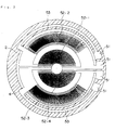
- FIG. 1 is a vertical cross-sectional view explaining the structure of the pressure sensor taken at line B-B of FIG. 2.
- FIG. 2 is a horizontal cross-sectional view taken at line A-A of FIG. 1.
- the strain gage pressure sensor 1 of the present invention structured by layering a insulated diaphragm 2 forming a strain gage comprising a resistor 5 on its surface and a insulated substrate 3 with an adhesive having a predetermined thickness.
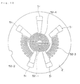
- Electrode pads 51, resistors 52-1 through 52-4 and a lead wire 53 for connecting the resistors and the electrode pads are formed on the surface of the diaphragm by screen printing and the like.
- the mechanical deformation of the diaphragm occurring by the impression of stress such as pressure changes the resist value of the resistor 52 forming the strain gage, and converts to a change in electric output of the bridge.
- insulators such as ceramic (sinter) of alumina or zirconia, silicon (Si), crystal and the like
- the diaphragm 2 and the substrate 3 is connected, for example, by applying and baking low-melting glass paste.
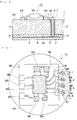
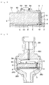
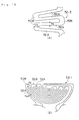
- FIG. 7 and FIG. 8 are utilized to explain a structure of another embodiment of a strain gage-type pressure sensor utilizing the strain gage-type pressure sensor described above.
- FIG. 7 is an upper view of the strain gage-type pressure sensor
- FIG. 8 is a partial cross-sectional side view of the same.
- the present embodiment solves such problem by printing the pattern of the strain gage using a ruthenium tetroxide (RuO 2 ) paste or silver-palladium (Ag-Pd) alloy paste, and then baking it to form the strain gage to be mounted on the diaphragm 2.
- RuO 2 ruthenium tetroxide
- Ag-Pd silver-palladium
- the present embodiment utilizes a glass having a higher melting point than the sealing glass for said protective material, and baked the protective material with a condition that differs from that recommended for said glass material, in order to reduce the strength of said over-coating glass.
- FIG. 15 The structure of said embodiment is shown in FIG. 15.
- the resistance value of the resistor structured by this printing pattern is adjusted by a trimming and the like by a laser in order to gain an output voltage proportionate to the pressure added to the diaphragm.
- the adhesive 4 utilizes a low-melting glass for example as its material, and adheres the substrate 3 and the diaphragm 2 so that a gap of about 50 ⁇ m is formed.
- the surface of the strain gage is covered by a glass having high melting point or high-temperature ceramic. Therefore, the protective material will not melt even when the sealing material is being baked at the time of assembling, and the deterioration of the coating could be prevented.
- the coating material has high insulating ability and mechanical strength, so a highly reliable pressure sensor could be gained.
- the ceramic of alumina or zirconia and silicon used in the present invention works as a perfect elastic body against stress showing characters such as high flexural strength, high resistance, small mechanical hysteresis and so on. Therefore, when utilized as a diaphragm of a strain gage-type pressure sensor, a pressure sensor with high accuracy and repeatability could be gained.
- the output error caused by the change in air pressure according to the height the pressure sensor is placed when used in a closed cycle such as a refrigeration cycle could be prevented.
- a low-humidity, inert atmosphere is formed inside said gap, so the strain gage is free from dampproofing and corrosion of migration and the like caused by the contamination from the peripheral portion.
- the substrate 3 could prevent the rapid discharge of the pressure medium.
- a simple structured electric circuit converting the difference in pressure to an electric output is gained having exceeded electrical characters than the capacitance-operated types.
- the resistors have no angle of the return portions and bend portions to form a circle so that no micro crack will occur, gaining high reliability. Further, the reduction of the distance between the resistance pattern in some areas will be prevented, improving the productivity and showing high reliability in use.
- the surface of the strain gage is covered by a glass having high melting point or high-temperature ceramic. Therefore, the protective material would not melt even when the sealing material is being baked at the time of assembling, and the deterioration of the coating could be prevented.
- the coating material has high insulating ability and mechanical strength, so a highly reliable pressure sensor could be gained.
Abstract
Description
Claims (25)
- A pressure sensor comprising:an insulating diaphragm having a strain gage mounted on the surface thereof; anda substrate positioned opposing the surface of said diaphragm mounting the strain gage, the bottom surface thereof positioned so as to maintain a predetermined gap between said surface of the diaphragm mounting the strain gage; whereinan insulating body formed of ceramic such as alumina or zirconia, silicon or crystal is used as the diaphragm.
- The pressure sensor of claim 1 wherein said substrate is either formed of the same material as said diaphragm, or the surface opposing the diaphragm is formed of insulated metal.
- The pressure sensor of claim 1 wherein said diaphragm and said substrate are fixed using a fixing means.
- The pressure sensor of claim 1 wherein:said substrate is either formed of the same material as said diaphragm, or the surface opposing the diaphragm is formed of insulated metal; andsaid diaphragm and said substrate are fixed using a fixing means.
- The pressure sensor of claim 1 wherein:said diaphragm and said substrate are fixed using a fixing means; andsaid fixing means is an adhesive comprising a low-melting glass or a thermosetting resin.
- The pressure sensor of claim 1 wherein:said substrate is either formed of the same material as said diaphragm, or the surface opposing the diaphragm is formed of insulated metal;said diaphragm and said substrate are fixed using a fixing means; andsaid fixing means is an adhesive comprising a low-melting glass or a thermosetting resin.
- The pressure sensor of claim 1 wherein:said diaphragm and said substrate are fixed using a fixing means;said fixing means is an adhesive comprising a low-melting glass or a thermosetting resin; anda gap forming member having a predetermined diameter is included in said adhesive.
- The pressure sensor of claim 1 wherein:said substrate is either formed of the same material as said diaphragm, or the surface opposing the diaphragm is formed of insulated metal;said diaphragm and said substrate are fixed using a fixing means;said fixing means is an adhesive comprising a low-melting glass or a thermosetting resin; anda gap forming member having a predetermined diameter is included in said adhesive.
- The pressure sensor of claim 1 wherein said gap is formed by forming a concave on the bottom surface of said substrate.
- The pressure sensor of claim 1 wherein:said substrate is either formed of the same material as said diaphragm, or the surface opposing the diaphragm is formed of insulated metal; andsaid gap is formed by forming a concave on the bottom surface of said substrate.
- The pressure sensor of claim 1 wherein:said diaphragm and said substrate are fixed using a fixing means; andsaid gap is formed by forming a concave on the bottom surface of said substrate.
- The pressure sensor of claim 1 wherein:said substrate is either formed of the same material as said diaphragm, or the surface opposing the diaphragm is formed of insulated metal;said diaphragm and said substrate are fixed using a fixing means; andsaid gap is formed by forming a concave on the bottom surface of said substrate.
- The pressure sensor of claim 1 wherein:said diaphragm and said substrate are fixed using a fixing means;said fixing means is an adhesive comprising a low-melting glass or a thermosetting resin; andsaid gap is formed by forming a concave on the bottom surface of said substrate.
- The pressure sensor of claim 1 wherein:said substrate is either formed of the same material as said diaphragm, or the surface opposing the diaphragm is formed of insulated metal;said diaphragm and said substrate are fixed using a fixing means;said fixing means is an adhesive comprising a low-melting glass or a thermosetting resin; andsaid gap is formed by forming a concave on the bottom surface of said substrate.
- A pressure sensor comprising:an insulating diaphragm having a strain gage mounted on the surface thereof; anda substrate positioned opposing the surface of said diaphragm mounting the strain gage, the bottom surface thereof positioned so as to maintain a predetermined gap between said surface of the diaphragm mounting the strain gage; whereinan electric circuit wiring pattern is formed on the surface of said substrate.
- A pressure sensor comprising:an insulating diaphragm having a strain gage mounted on the surface thereof; anda substrate positioned opposing the surface of said diaphragm mounting the strain gage, the bottom surface thereof positioned so as to maintain a predetermined gap between said surface of the diaphragm mounting the strain gage; whereina circuit board having an electric circuit wiring pattern is adhered to the surface of said substrate.
- A pressure sensor comprising:an insulating diaphragm having a strain gage mounted on the surface thereof; anda substrate positioned opposing the surface of said diaphragm mounting the strain gage, the bottom surface thereof positioned so as to maintain a predetermined gap between said surface of the diaphragm mounting the strain gage; whereinan electric circuit is placed on the surface of said substrate, and said pressure sensor is fixed inside a container through an elastic member.
- A pressure sensor comprising:an insulating diaphragm having a strain gage mounted on the surface thereof; anda substrate positioned opposing the surface of said diaphragm mounting the strain gage, the bottom surface thereof positioned so as to maintain a predetermined gap between said surface of the diaphragm mounting the strain gage; whereinan insulating body formed of ceramic such as alumina or zirconia, silicon or crystal is used as the diaphragm; anda return portion of a resistor for the strain gage formed on said substrate has no angle on the angle portion of said return portion so as to form a circle.
- A pressure sensor comprising:an insulating diaphragm having a strain gage mounted on the surface thereof; anda substrate positioned opposing the surface of said diaphragm mounting the strain gage, the bottom surface thereof positioned so as to maintain a predetermined gap between said surface of the diaphragm mounting the strain gage; whereinan insulating body formed of ceramic such as alumina or zirconia, silicon or crystal is used as the diaphragm; andthe resistance value of a return portion of a resistor for the strain gage formed on said substrate is reduced.
- The pressure sensor of claim 19 wherein the resistance value of the return portion of the resistor for the strain gage formed on said substrate is reduced by forming the return portion by a low resistance material.
- The pressure sensor of claim 19 wherein the resistance value of the return portion of the resistor for the strain gage formed on said substrate is reduced by widening the width of said return portion.
- A pressure sensor comprising:an insulating diaphragm having a strain gage mounted on the surface thereof; anda substrate positioned opposing the surface of said diaphragm mounting the strain gage, the bottom surface thereof positioned so as to maintain a predetermined gap between said surface of the diaphragm mounting the strain gage; whereinan insulating body formed of ceramic such as alumina or zirconia, silicon or crystal is used as the diaphragm; anda resistor for the strain gage mounted on said substrate is formed by printing.
- The pressure sensor of claim 22 wherein a silver-palladium alloy paste material or a ruthenium tetroxide paste material is printed and baked to form said resistor.
- A pressure sensor comprising:an insulating diaphragm having a strain gage mounted on the surface thereof; anda substrate positioned opposing the surface of said diaphragm mounting the strain gage, the bottom surface thereof positioned so as to maintain a predetermined gap between said surface of the diaphragm mounting the strain gage; whereinan insulating body formed of ceramic such as alumina or zirconia, silicon or crystal is used as the diaphragm; anda surface of a resistor for the strain gage mounted on said substrate is covered with a protective material.
- The pressure sensor of claim 24 wherein a glass having higher melting point than the baking temperature of a sealing member is utilized as said protective material.
Applications Claiming Priority (7)
| Application Number | Priority Date | Filing Date | Title |
|---|---|---|---|
| JP24771196 | 1996-09-19 | ||
| JP247711/96 | 1996-09-19 | ||
| JP24771196 | 1996-09-19 | ||
| JP98975/97 | 1997-04-16 | ||
| JP9897597 | 1997-04-16 | ||
| JP9098975A JPH10148591A (en) | 1996-09-19 | 1997-04-16 | Pressure detector |
| US08/927,269 US6003380A (en) | 1996-09-19 | 1997-09-11 | Strain gage pressure sensor wherein a gap is maintained between the diaphragm and the substrate |
Publications (3)
| Publication Number | Publication Date |
|---|---|
| EP0831315A2 true EP0831315A2 (en) | 1998-03-25 |
| EP0831315A3 EP0831315A3 (en) | 1998-12-16 |
| EP0831315B1 EP0831315B1 (en) | 2001-10-17 |
Family
ID=27308809
Family Applications (1)
| Application Number | Title | Priority Date | Filing Date |
|---|---|---|---|
| EP97116173A Expired - Lifetime EP0831315B1 (en) | 1996-09-19 | 1997-09-17 | Pressure sensor |
Country Status (5)
| Country | Link |
|---|---|
| US (1) | US6003380A (en) |
| EP (1) | EP0831315B1 (en) |
| JP (1) | JPH10148591A (en) |
| DE (1) | DE69707386T2 (en) |
| ES (1) | ES2163696T3 (en) |
Cited By (5)
| Publication number | Priority date | Publication date | Assignee | Title |
|---|---|---|---|---|
| WO2001006098A1 (en) * | 1999-07-19 | 2001-01-25 | Siemens Aktiengesellschaft | Device and method for aftertreating the exhaust gas of an internal combustion engine by means of selective catalytic reduction |
| WO2005024370A1 (en) * | 2003-09-02 | 2005-03-17 | Auxitrol S.A. | Protection of a deformable membrane against large deformations in a micromechanical structure |
| WO2007096225A1 (en) * | 2006-02-24 | 2007-08-30 | Commissariat A L'energie Atomique | Pressure sensor with resistive gauges |
| EP3696526A1 (en) | 2008-06-19 | 2020-08-19 | Eltek S.p.A. | Pressure sensor device |
| CN112484630A (en) * | 2020-12-09 | 2021-03-12 | 湖南启泰传感科技有限公司 | Thin film resistance strain pressure sensor and layout optimization method thereof |
Families Citing this family (37)
| Publication number | Priority date | Publication date | Assignee | Title |
|---|---|---|---|---|
| US6782754B1 (en) | 2000-07-07 | 2004-08-31 | Rosemount, Inc. | Pressure transmitter for clean environments |
| WO2002008711A1 (en) * | 2000-07-26 | 2002-01-31 | Robert Bosch Gmbh | Production method for a thin-layer component, especially a thin-layer high pressure sensor, and corresponding thin-layer component |
| US6688185B2 (en) | 2001-08-20 | 2004-02-10 | Autoliv Asp, Inc. | System and method for microstrain measurement |
| JP4111136B2 (en) | 2001-10-02 | 2008-07-02 | 松下電器産業株式会社 | Strain sensor and manufacturing method thereof |
| DE10221219B4 (en) * | 2002-05-13 | 2007-06-28 | Ifm Electronic Gmbh | pressure sensor |
| JP4518467B2 (en) * | 2002-09-17 | 2010-08-04 | 株式会社ハーモニック・ドライブ・システムズ | Torque detection device for wave gear device |
| US7210362B2 (en) * | 2002-11-05 | 2007-05-01 | Tanita Corporation | Diaphragm type load detection sensor, load detection unit and electronic scale using same |
| US7093495B2 (en) * | 2003-07-28 | 2006-08-22 | Cts Corporation | Pressure sensor |
| JP4404297B2 (en) * | 2003-09-03 | 2010-01-27 | 株式会社山武 | Flow sensor |
| US6997059B2 (en) * | 2003-10-07 | 2006-02-14 | Cts Corporation | Pressure sensor |
| US7240558B2 (en) * | 2003-11-19 | 2007-07-10 | Cts Corporation | Pressure sensor |
| US20050103110A1 (en) * | 2003-11-19 | 2005-05-19 | Cts Corporation | Integrated pressure and temperature sensor |
| JP2007516746A (en) * | 2003-12-11 | 2007-06-28 | プロテウス バイオメディカル インコーポレイテッド | Implantable pressure sensor |
| US7347099B2 (en) * | 2004-07-16 | 2008-03-25 | Rosemount Inc. | Pressure transducer with external heater |
| US20090038400A1 (en) * | 2004-09-13 | 2009-02-12 | Pall Corporation | Pressure Sensing Devices and Fluid Assemblies |
| US7295131B2 (en) * | 2005-01-07 | 2007-11-13 | Rosemount Inc. | Diagnostic system for detecting rupture or thinning of diaphragms |
| US7679033B2 (en) * | 2005-09-29 | 2010-03-16 | Rosemount Inc. | Process field device temperature control |
| JP4983176B2 (en) * | 2006-09-14 | 2012-07-25 | セイコーエプソン株式会社 | Manufacturing method of pressure sensor |
| JP5034664B2 (en) * | 2007-05-09 | 2012-09-26 | 株式会社豊田中央研究所 | Force detector |
| WO2009043040A1 (en) * | 2007-09-28 | 2009-04-02 | Endevco Corporation | Silicon sensing structure to detect through-plane motion a plane of material with thermal expansion substantially different from that of silicon |
| US7779698B2 (en) * | 2007-11-08 | 2010-08-24 | Rosemount Inc. | Pressure sensor |
| ITTO20120293A1 (en) | 2012-04-03 | 2013-10-04 | Metallux Sa | PROCEDURE FOR CALIBRATING A CALIBRATION ELEMENT AND ITS DEVICE |
| JP6022881B2 (en) * | 2012-10-04 | 2016-11-09 | 公益財団法人電磁材料研究所 | Strain gauge |
| EP2720019A1 (en) * | 2012-10-10 | 2014-04-16 | Auto Industrial Co., Ltd. | Pressure transducer using ceramic diaphragm |
| US8943896B2 (en) * | 2012-10-10 | 2015-02-03 | Auto Industrial Co., Ltd. | Pressure transducer using ceramic diaphragm |
| ITTO20121130A1 (en) * | 2012-12-21 | 2014-06-22 | Metallux Sa | PRESSURE SENSOR |
| DE102013011157B3 (en) * | 2013-07-04 | 2015-01-08 | Mario Cerino | Sensor element with divided into four segments sensor layer and method for its preparation |
| US9890033B2 (en) * | 2015-04-06 | 2018-02-13 | Honeywell International Inc. | Silicon-on-sapphire device with minimal thermal strain preload and enhanced stability at high temperature |
| JP6492257B2 (en) * | 2015-06-11 | 2019-04-03 | ユニパルス株式会社 | Force transducer and strain gauge used therefor |
| JP2019045205A (en) * | 2017-08-30 | 2019-03-22 | アイシン精機株式会社 | Load detector |
| JP2020053433A (en) * | 2018-09-21 | 2020-04-02 | Koa株式会社 | Strain sensor resistor |
| EP3671159B1 (en) * | 2018-12-21 | 2022-12-21 | Exentis Knowledge GmbH | Body formed by an additive manufacturing method and method for manufacturing the same |
| CN113302465A (en) * | 2019-01-18 | 2021-08-24 | 日本电产新宝株式会社 | Torque detection sensor and power transmission device |
| JP7302767B2 (en) * | 2019-06-27 | 2023-07-04 | ニデックドライブテクノロジー株式会社 | Torque detection sensor and power transmission |
| JP7352877B2 (en) * | 2019-12-16 | 2023-09-29 | ニデックドライブテクノロジー株式会社 | Torque detection sensor and power transmission device |
| JP7396588B2 (en) * | 2019-12-16 | 2023-12-12 | ニデックドライブテクノロジー株式会社 | Strain detection sensor and power transmission device |
| CN112484631B (en) * | 2020-12-09 | 2022-01-11 | 湖南启泰传感科技有限公司 | Film pressure sensor and layout method thereof |
Citations (13)
| Publication number | Priority date | Publication date | Assignee | Title |
|---|---|---|---|---|
| US3078431A (en) * | 1959-07-08 | 1963-02-19 | Ivanhoe P Denyssen | Strain gage and method of manufacture |
| US4079508A (en) * | 1975-08-13 | 1978-03-21 | The Board Of Trustees Of The Leland Stanford Junior University | Miniature absolute pressure transducer assembly and method |
| US4086554A (en) * | 1975-11-12 | 1978-04-25 | Daimler-Benz Aktiengesellschaft | Strain gauge |
| US4311980A (en) * | 1978-10-12 | 1982-01-19 | Fabrica Italiana Magneti Marelli, S.P.A. | Device for pressure measurement using a resistor strain gauge |
| US4399707A (en) * | 1981-02-04 | 1983-08-23 | Honeywell, Inc. | Stress sensitive semiconductor unit and housing means therefor |
| US4481497A (en) * | 1982-10-27 | 1984-11-06 | Kulite Semiconductor Products, Inc. | Transducer structures employing ceramic substrates and diaphragms |
| US4993267A (en) * | 1988-04-08 | 1991-02-19 | General Electric Company | Electronic transducer |
| US5209122A (en) * | 1991-11-20 | 1993-05-11 | Delco Electronics Corporation | Pressurer sensor and method for assembly of same |
| US5224384A (en) * | 1991-06-07 | 1993-07-06 | Maclean-Fogg Company | Resistive strain gauge pressure sensor |
| US5227760A (en) * | 1990-09-29 | 1993-07-13 | Toshihiro Kobayashi | Strain gage |
| US5349867A (en) * | 1991-12-02 | 1994-09-27 | Kavlico Corporation | Sensitive resistive pressure transducer |
| US5481905A (en) * | 1992-11-03 | 1996-01-09 | Philips Electronics North America Corporation | Transducer circuit having negative integral feedback |
| EP0762096A1 (en) * | 1995-09-05 | 1997-03-12 | Motorola, Inc. | Vertically integrated sensor structure and method for making same |
Family Cites Families (5)
| Publication number | Priority date | Publication date | Assignee | Title |
|---|---|---|---|---|
| JPS6212458A (en) * | 1985-07-09 | 1987-01-21 | Fuji Heavy Ind Ltd | Safety device for motor-driven power steering for automobile |
| US4766666A (en) * | 1985-09-30 | 1988-08-30 | Kabushiki Kaisha Toyota Chuo Kenkyusho | Semiconductor pressure sensor and method of manufacturing the same |
| US4617607A (en) * | 1985-12-10 | 1986-10-14 | Kavlico Corporation | High pressure capacitive transducer |
| CN1018844B (en) * | 1990-06-02 | 1992-10-28 | 中国科学院兰州化学物理研究所 | Antirust dry film lubricant |
| US5349865A (en) * | 1993-08-30 | 1994-09-27 | Kavlico Corporation | Wide-pressure-range, adaptable, simplified pressure transducer |
-
1997
- 1997-04-16 JP JP9098975A patent/JPH10148591A/en active Pending
- 1997-09-11 US US08/927,269 patent/US6003380A/en not_active Expired - Fee Related
- 1997-09-17 DE DE69707386T patent/DE69707386T2/en not_active Expired - Fee Related
- 1997-09-17 EP EP97116173A patent/EP0831315B1/en not_active Expired - Lifetime
- 1997-09-17 ES ES97116173T patent/ES2163696T3/en not_active Expired - Lifetime
Patent Citations (13)
| Publication number | Priority date | Publication date | Assignee | Title |
|---|---|---|---|---|
| US3078431A (en) * | 1959-07-08 | 1963-02-19 | Ivanhoe P Denyssen | Strain gage and method of manufacture |
| US4079508A (en) * | 1975-08-13 | 1978-03-21 | The Board Of Trustees Of The Leland Stanford Junior University | Miniature absolute pressure transducer assembly and method |
| US4086554A (en) * | 1975-11-12 | 1978-04-25 | Daimler-Benz Aktiengesellschaft | Strain gauge |
| US4311980A (en) * | 1978-10-12 | 1982-01-19 | Fabrica Italiana Magneti Marelli, S.P.A. | Device for pressure measurement using a resistor strain gauge |
| US4399707A (en) * | 1981-02-04 | 1983-08-23 | Honeywell, Inc. | Stress sensitive semiconductor unit and housing means therefor |
| US4481497A (en) * | 1982-10-27 | 1984-11-06 | Kulite Semiconductor Products, Inc. | Transducer structures employing ceramic substrates and diaphragms |
| US4993267A (en) * | 1988-04-08 | 1991-02-19 | General Electric Company | Electronic transducer |
| US5227760A (en) * | 1990-09-29 | 1993-07-13 | Toshihiro Kobayashi | Strain gage |
| US5224384A (en) * | 1991-06-07 | 1993-07-06 | Maclean-Fogg Company | Resistive strain gauge pressure sensor |
| US5209122A (en) * | 1991-11-20 | 1993-05-11 | Delco Electronics Corporation | Pressurer sensor and method for assembly of same |
| US5349867A (en) * | 1991-12-02 | 1994-09-27 | Kavlico Corporation | Sensitive resistive pressure transducer |
| US5481905A (en) * | 1992-11-03 | 1996-01-09 | Philips Electronics North America Corporation | Transducer circuit having negative integral feedback |
| EP0762096A1 (en) * | 1995-09-05 | 1997-03-12 | Motorola, Inc. | Vertically integrated sensor structure and method for making same |
Cited By (8)
| Publication number | Priority date | Publication date | Assignee | Title |
|---|---|---|---|---|
| WO2001006098A1 (en) * | 1999-07-19 | 2001-01-25 | Siemens Aktiengesellschaft | Device and method for aftertreating the exhaust gas of an internal combustion engine by means of selective catalytic reduction |
| US6519935B2 (en) | 1999-07-19 | 2003-02-18 | Siemens Aktiengesellschaft | Device and method for exhaust-gas aftertreatment in an internal-combustion engine |
| WO2005024370A1 (en) * | 2003-09-02 | 2005-03-17 | Auxitrol S.A. | Protection of a deformable membrane against large deformations in a micromechanical structure |
| WO2007096225A1 (en) * | 2006-02-24 | 2007-08-30 | Commissariat A L'energie Atomique | Pressure sensor with resistive gauges |
| FR2897937A1 (en) * | 2006-02-24 | 2007-08-31 | Commissariat Energie Atomique | Pressure sensor for tire of vehicle, has deformable membrane with insulant material layer, and resistive gauge integrated to insulant material layer and situated below membrane inside cavity which is closed by substrate and membrane |
| US8393223B2 (en) | 2006-02-24 | 2013-03-12 | Commissariat A L'energie Atomique | Pressure sensor with resistance strain gages |
| EP3696526A1 (en) | 2008-06-19 | 2020-08-19 | Eltek S.p.A. | Pressure sensor device |
| CN112484630A (en) * | 2020-12-09 | 2021-03-12 | 湖南启泰传感科技有限公司 | Thin film resistance strain pressure sensor and layout optimization method thereof |
Also Published As
| Publication number | Publication date |
|---|---|
| EP0831315A3 (en) | 1998-12-16 |
| EP0831315B1 (en) | 2001-10-17 |
| US6003380A (en) | 1999-12-21 |
| DE69707386T2 (en) | 2002-05-23 |
| DE69707386D1 (en) | 2001-11-22 |
| JPH10148591A (en) | 1998-06-02 |
| ES2163696T3 (en) | 2002-02-01 |
Similar Documents
| Publication | Publication Date | Title |
|---|---|---|
| EP0831315B1 (en) | Pressure sensor | |
| US7441467B2 (en) | Compression strain sensor | |
| EP0354479B1 (en) | Semiconductor pressure sensor | |
| US4481497A (en) | Transducer structures employing ceramic substrates and diaphragms | |
| US4311980A (en) | Device for pressure measurement using a resistor strain gauge | |
| US4583296A (en) | Electrical inclination sensor and method for its manufacture | |
| US5712428A (en) | Pressure sensor with a solid to minimize temperature-related measurement error | |
| US5335549A (en) | Semiconductor pressure sensor having double diaphragm structure | |
| JP3546059B2 (en) | Pressure sensor components that can be assembled on the mounting surface of a printed wiring board | |
| US5877425A (en) | Semiconductor-type pressure sensor with sensing based upon pressure or force applied to a silicon plate | |
| US5209120A (en) | Semiconductor pressure-detecting apparatus | |
| JP3662018B2 (en) | Pressure sensor for detecting the pressure in the combustion chamber of an internal combustion engine | |
| JP3190333B2 (en) | Pressure sensor for detecting pressure in a combustion chamber of an internal combustion engine | |
| JPH11514153A (en) | Component casing for surface mounting semiconductor components | |
| US6997059B2 (en) | Pressure sensor | |
| US7240558B2 (en) | Pressure sensor | |
| US20050103110A1 (en) | Integrated pressure and temperature sensor | |
| JPH095191A (en) | Capacitance type pressure sensor | |
| CN107490337B (en) | Strain detector and method for manufacturing the same | |
| US7093495B2 (en) | Pressure sensor | |
| JP3607420B2 (en) | Dry type pressure detector | |
| JPH02196938A (en) | Pressure sensor | |
| US7475607B2 (en) | Sensing apparatus with an integrated gasket on a beam component | |
| EP0710827A2 (en) | Combustion pressure sensor and fabrication method thereof | |
| EP1552260B1 (en) | Pressure sensor and production thereof |
Legal Events
| Date | Code | Title | Description |
|---|---|---|---|
| PUAI | Public reference made under article 153(3) epc to a published international application that has entered the european phase |
Free format text: ORIGINAL CODE: 0009012 |
|
| AK | Designated contracting states |
Kind code of ref document: A2 Designated state(s): DE ES FR GB IT NL |
|
| AX | Request for extension of the european patent |
Free format text: AL;LT;LV;RO;SI |
|
| PUAL | Search report despatched |
Free format text: ORIGINAL CODE: 0009013 |
|
| AK | Designated contracting states |
Kind code of ref document: A3 Designated state(s): AT BE CH DE DK ES FI FR GB GR IE IT LI LU MC NL PT SE |
|
| AX | Request for extension of the european patent |
Free format text: AL;LT;LV;RO;SI |
|
| 17P | Request for examination filed |
Effective date: 19990208 |
|
| 17Q | First examination report despatched |
Effective date: 19990324 |
|
| AKX | Designation fees paid |
Free format text: DE ES FR GB IT NL |
|
| GRAG | Despatch of communication of intention to grant |
Free format text: ORIGINAL CODE: EPIDOS AGRA |
|
| GRAG | Despatch of communication of intention to grant |
Free format text: ORIGINAL CODE: EPIDOS AGRA |
|
| GRAH | Despatch of communication of intention to grant a patent |
Free format text: ORIGINAL CODE: EPIDOS IGRA |
|
| GRAH | Despatch of communication of intention to grant a patent |
Free format text: ORIGINAL CODE: EPIDOS IGRA |
|
| GRAA | (expected) grant |
Free format text: ORIGINAL CODE: 0009210 |
|
| AK | Designated contracting states |
Kind code of ref document: B1 Designated state(s): DE ES FR GB IT NL |
|
| REF | Corresponds to: |
Ref document number: 69707386 Country of ref document: DE Date of ref document: 20011122 |
|
| REG | Reference to a national code |
Ref country code: GB Ref legal event code: IF02 |
|
| ET | Fr: translation filed | ||
| REG | Reference to a national code |
Ref country code: ES Ref legal event code: FG2A Ref document number: 2163696 Country of ref document: ES Kind code of ref document: T3 |
|
| PLBE | No opposition filed within time limit |
Free format text: ORIGINAL CODE: 0009261 |
|
| STAA | Information on the status of an ep patent application or granted ep patent |
Free format text: STATUS: NO OPPOSITION FILED WITHIN TIME LIMIT |
|
| PG25 | Lapsed in a contracting state [announced via postgrant information from national office to epo] |
Ref country code: GB Free format text: LAPSE BECAUSE OF NON-PAYMENT OF DUE FEES Effective date: 20020917 |
|
| PG25 | Lapsed in a contracting state [announced via postgrant information from national office to epo] |
Ref country code: ES Free format text: LAPSE BECAUSE OF NON-PAYMENT OF DUE FEES Effective date: 20020918 |
|
| 26N | No opposition filed | ||
| PG25 | Lapsed in a contracting state [announced via postgrant information from national office to epo] |
Ref country code: NL Free format text: LAPSE BECAUSE OF NON-PAYMENT OF DUE FEES Effective date: 20030401 Ref country code: DE Free format text: LAPSE BECAUSE OF NON-PAYMENT OF DUE FEES Effective date: 20030401 |
|
| GBPC | Gb: european patent ceased through non-payment of renewal fee |
Effective date: 20020917 |
|
| PG25 | Lapsed in a contracting state [announced via postgrant information from national office to epo] |
Ref country code: FR Free format text: LAPSE BECAUSE OF NON-PAYMENT OF DUE FEES Effective date: 20030603 |
|
| REG | Reference to a national code |
Ref country code: FR Ref legal event code: ST |
|
| REG | Reference to a national code |
Ref country code: ES Ref legal event code: FD2A Effective date: 20031011 |
|
| PG25 | Lapsed in a contracting state [announced via postgrant information from national office to epo] |
Ref country code: IT Free format text: LAPSE BECAUSE OF NON-PAYMENT OF DUE FEES Effective date: 20050917 |