背景技術
本発明はドイツ連邦共和国特許公開公報第3125640.6号に基づき公知の圧力センサから出発する。この公知の圧力センサにおいては、ピエゾ抵抗形の測定素子、例えばサーメット、導電性プラスチックまたは金属からなる厚膜抵抗が支持体に被着されている。抵抗素子と支持体とは、圧力室内の圧力を測定することができるように圧力室の出来るだけ近くに配置されている。さらに測定信号は、電気的な導線を用いて圧力センサのケーシングの外部に配置された電子評価回路に案内されている。したがってピエゾ抵抗形の素子と電子的な構成部材とはシールドされた導線を用いて互いに接続されなければならず、これには手間がかかる。ピエゾ抵抗形の測定素子は圧力に直接さらされるので、圧力室内の高温にもさらされることになる。この圧力室には約2000℃の温度で火炎が広がる。これによって、ケーシングには歪みが生じてしまうことがある。したがって圧力信号は高温により誤められてしまう。
さらに米国特許第4645965号明細書に開示された圧力センサにおいては、測定センサが圧電性材料から成っている。圧電性の素子としては例えば圧電セラミック素子が使用されている。この圧電セラミック素子は、線材をコンタクト板に溶接することにより接触接続することができる。しかしこれには手間がかかる。ピエゾ抵抗形の素子とは異なり、圧電性の素子では圧力作用時に測定信号が形成される際に電荷ひいては電圧が形成される。この電圧が取出され、評価されるのである。これとは異なり、ピエゾ抵抗形の素子では、電圧が印加され、ピエゾ抵抗形の素子における電気抵抗が圧力作用によって変化させられる。
発明の利点
請求項1に記載の特徴を有する本発明の圧力センサには次のような利点がある。すなわち単結晶のシリコンチップにピエゾ抵抗形の測定素子と電子処理装置とを極めてスペース節約型のコンパクトな構造で配置することができる。センサの感度は、組立てが完了した状態で外部から調節することができる。本発明の圧力センサにおいては従来の技術背景とは異なりレーザ調整はもはや不要である。
従属形式請求項に記載の手段により、請求項1に記載のセンサの有利な手段が得られる。
図面
以下に本発明の実施例を図面につき詳しく説明する。第1図は圧力センサの断面図であり、第2図は回路図であり、第3a図および第3b図は、1変化実施例を断面図と平面図とで示しており、第4図は別の変化実施例の断面図である。
実施例の説明
第1図には内燃機関の燃焼室内の圧力を測定するための圧力センサ11のケーシングが符号10で示されている。このケーシングは中央に、一貫して延びかつ段付けされた孔12を有している。ケーシング10の、燃焼室に面した開口部13はダイヤフラム14によって閉鎖されている。ダイヤフラム14はいわゆるキャップ形ダイヤフラムとして構成されている。ダイヤフラムの縁部は折り曲げられており、ケーシング10の軸部15の端部に被せられていて、そこで溶接固定されている。これによりダイヤフラム14はケーシング10にしっかりと装着されているが、ダイヤフラム14の可動性を保証するために、軸部15の端面16には直接接触していない。したがってダイヤフラム14の曲がった部分は自由に運動することができる。しかしダイヤフラムは、例えばスナップ結合のようなほかの形式によってケーシング10の軸部15に固定することもできる。ダイヤフラム14は、超合金、すなわち、例えばほぼNi50%とCr20%とFe20%との合金から構成されていると特に有利である。ダイヤフラム14の中央部にはプランジャ18の一方の端部が当接しており、プランジャ18の他方の端部は、単結晶のシリコン(Si)チップ20のピエゾ抵抗形の測定素子19に当接している。ピエゾ抵抗形の測定素子とは、圧力作用を受けてその抵抗値を変化させるような素子を意味する。測定素子19は拡散と、半導体技術に基づき公知の他の方法とにより製造されたピエゾ抵抗形の抵抗21から成っている。この抵抗21にはプランジャ18の力が直角方向で導入される。前記の抵抗の製造方法ではシリコンプレートの異種原子とのドーピングが行なわれる。実際にはこの場合例えばホウ素またはリンが使用される。さらに測定素子19は、すぐ近くに配置された第2の抵抗22を有している(第2図)。しかしこの抵抗22には圧力は作用しない。
この抵抗22は抵抗21と同様に前記の方法で製造されている。抵抗22は抵抗21を補完していわゆる半波整流ブリッジ回路を形成している。場合によっては、別の2つの抵抗を加えて都合3つの抵抗を設けてもよい。これらの抵抗には圧力が作用せず、これによりホイートストン形の全波整流ブリッジ回路が得られる。さらにシリコンチップには安定化回路23が形成されていて、これにより測定素子19には安定化されかつ外乱を取り除かれた電圧または電流が供給される。さらに抵抗21,22の測定ブリッジには直流電圧または交流電圧の増幅回路24が作用する。これにより測定信号をミリボルト領域からボルト領域に増幅することができる。しかしその代わりに一般に公知の、増幅作用を有する制御回路がシリコンチップに設けられていてもよい。測定素子19の測定ブリッジの近傍には温度依存型の抵抗25または半導体素子が配置されており、これによってブリッジ抵抗の温度依存性ならびに使用されるピエゾ抵抗形の素子のピエゾ抵抗係数が補償される。さらにシリコンチップには、抵抗27と、例えば並列に接続された抵抗51と、これに直列接続されたツェナーダイオード28とからなる回路網ならびに機能のバランスのためのロジック素子29が設けられている。このためにはロジック素子29から付加的な接続部31がチップから外部へ向かって案内されている。必要に応じて極めて高い電圧と電流とを印加することによりツェナーダイオード28をブレークダウンさせひいては抵抗51を回路網に並列に接続させることができるほどの高い電圧と電流とが前記接続部に加えられるようになっている。これにより、例えば測定素子19への規定の圧力の印加時に、センサのゼロ点と感度とが外部から電気的にバランス可能となる。場合によってはこのようにして温度特性が温度依存型の抵抗25を介して影響されるようになっていてもよい。従来より公知の圧力センサにおいてはこのような形式の機能のバランスは、厚膜ハイブリッド上の抵抗のレーザバランシングによってのみ可能である。しかし厚膜回路は比較的大きな所要スペースを有しており、これによりセンサの外寸法を決定してしまう。
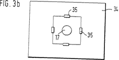
第3図に示した測定素子の実施態様では、シリコン結晶20aからエッチング加工されかつダイヤフラムとして働く薄い部分に4つの抵抗35が形成されている。これらの4つの抵抗35はホイートストン形のブリッジ回路内に接続されており、この場合力はダイヤフラム34の中央に導入され、これにより抵抗35は縦方向または横方向で引張応力または圧縮応力を受ける。この場合チップは第2図に示したように構成されている。第3図に示した配置形式は第1図に示した構成にも同様に使用可能である。この場合プランジャ18は抵抗の1つに載置されることなくホイートストン形のブリッジ回路の中央に作用し、第1図に示した通りシリコンチップ20はエッチング加工されたダイヤフラムを有していない。
プランジャ18はガラスセラミックスからなっていてもよく、これによりダイヤフラムすなわち圧力を測定しようとする圧力室と測定素子19との間の良好な断熱が保証される。プランジャ18の、チップ20に面した端部は円錐状に構成されていてもよい。これによりこの端部は測定素子19の敏感な抵抗とほぼ等しい直径を有することができるか、あるいはダイヤフラム34もしくはホイートストン形のブリッジ回路の中央に載置することができる。これによってプランジャ18を孔12内で案内するにもかかわらず、圧力伝達部分ではプランジャを測定素子19の大きさに制限することが可能になる。プランジャ18から測定素子19への、力のできるだけ正確に規定された導入を保証するために、プランジャ18は少なくともその端部領域17が比較的軟らかい材料から製造されている。これによりプランジャ端部の表面粗さが測定素子19の測定抵抗21に測定誤差として生じてしまうことを阻止できる。この場合、プランジャ端部の端面と測定素子19の表面との間に形状接続が得られる。ここではチップ20に中間素子36が配置されていてもよい。この中間素子は、正確に規定された載着面でプランジャ18の力を極めて均一に測定素子19に導入するために役立つ。しかもその際、測定素子19がプランジャ端部の粗く凹凸のある表面により破壊されたり付加的な横方向緊張が測定素子に生じたりすることはない。中間素子36は、ホウケイ酸ガラスまたは同様にシリコンからなっていると有利である。それというのはこれらの材料は熱膨張係数の点でシリコンチップに適合しておりしかも表面の質が高いからである。ホウケイ酸ガラスとしてはコーニング−グラスワークス社(Firma Corning−Glass Works、米国在)の材料パイレックス(Pyrex)またはショット社(Firma Schott、ドイツ連邦共和国、マインツ在)の材料テンパックス(Tempax)を使用してもよい。中間素子36は、エッチングにより加工されたいわゆる凸構造または第4図に示したようなメサ構造32を有していてもよい。メサ構造には平らな表面はもはや形成されておらず凸部および/または凹部が設けられている。例えばすでに製造過程において、シリコンチップを備えたウェーハと、メサ構造にエッチングされたパイレックスウェーハまたはシリコンウェーハとを陽極ボンディングするか、または直接にボンディングし、つまり両者を機械的に固く結合させ、続いてソーイングすることができる。これにより中間素子36の極めて高い位置調整精度が得られる。
さらに、プランジャ18全体を軟らかな材料から製造することも考えられる。しかしこうすることによりプランジャ18の剛性にはやはり不都合な影響がもたらされることがある。プランジャ18の材料を選択する際には次の点を考慮するのが望ましい。すなわち、プランジャはできるだけ小さな熱伝導率を有しているのがよく、これにより測定信号が温度の変動または温度自体による影響によって誤められることがなくなるのである。小さな熱伝導率は例えばガラスセラミックスが有している。プランジャ18の部分17のための材料は、例えば比較的軟質の金属、例えばAl、黄銅、Cuやプラスチック等が使用されてもよい。この軟らかい領域のための材料は小さい熱伝導率に合わせる必要はない。
チップ20は、孔12にプレス嵌めされた受け37に直接当接しているか、または支持体38を介してこの受けに結合されている。この支持体38は、シリコンチップ20と受け37との間に異なる膨張係数が作用するのを回避するようになっている。支持体の材料としてはシリコンまたはホウケイ酸ガラスが有利に適している。受け37内には孔12に対してほぼ軸平行に延びて貫通する複数の孔40が構成されている。これらの孔40内では、電気的に絶縁性のガラスコンパウンドによって取り囲まれた調整ピン31aと電気的な接続のためのピン47とが案内されている。ピン31a,47はボンディングワイヤ39を介してシリコンチップ20に接続されている。ピン47の導線48はマウスピース49に集められている。例えば湿リのような、環境からの有害な影響に対する保護のためには孔12がピンと電気的な回路とが存在する領域に封止用コンパウンド50を流し込まれていてもよい。The invention starts from a known pressure sensor according to German Offenlegungsschrift 3125640.6. In this known pressure sensor, a piezoresistive measuring element, for example a thick film resistor made of cermet, conductive plastic or metal, is applied to a support. The resistance element and the support are arranged as close as possible to the pressure chamber so that the pressure in the pressure chamber can be measured. Furthermore, the measurement signal is guided to an electronic evaluation circuit arranged outside the casing of the pressure sensor using electrical leads. Therefore, the piezoresistive element and the electronic component must be connected to each other using shielded wires, which is laborious. Since the piezoresistive measuring element is directly exposed to pressure, it is also exposed to high temperatures in the pressure chamber. A flame spreads in this pressure chamber at a temperature of about 2000 ° C. This can cause distortion in the casing. Therefore, the pressure signal is mistaken for high temperatures.
Furthermore, in the pressure sensor disclosed in US Pat. No. 4,645,965, the measurement sensor is made of a piezoelectric material. For example, a piezoelectric ceramic element is used as the piezoelectric element. This piezoelectric ceramic element can be contact-connected by welding a wire to a contact plate. However, this takes time. Unlike a piezoresistive element, a piezoelectric element generates a charge and thus a voltage when a measurement signal is generated when a pressure is applied. This voltage is extracted and evaluated. In contrast, in a piezoresistive element, a voltage is applied, and the electrical resistance in the piezoresistive element is changed by pressure.
Advantages of the Invention The pressure sensor of the present invention having the features described in claim 1 has the following advantages. That is, a piezoresistive measuring element and an electronic processing device can be arranged on a single crystal silicon chip with a very space-saving compact structure. The sensitivity of the sensor can be adjusted from the outside after assembly. In the pressure sensor of the present invention, unlike the prior art background, laser adjustment is no longer necessary.
By means of the dependent claims, advantageous means of the sensor according to claim 1 are obtained.
In the following, embodiments of the present invention will be described in detail with reference to the drawings. FIG. 1 is a sectional view of a pressure sensor, FIG. 2 is a circuit diagram, FIGS. 3a and 3b show a variation example in a sectional view and a plan view, and FIG. It is sectional drawing of another modified example.
DESCRIPTION OF THE PREFERRED EMBODIMENTS FIG. 1 shows a casing 10 of a pressure sensor 11 for measuring the pressure in a combustion chamber of an internal combustion engine. This casing has a centrally extending and stepped hole 12 in the center. An opening 13 of the casing 10 facing the combustion chamber is closed by a diaphragm 14. Diaphragm 14 is configured as a so-called cap-type diaphragm. An edge portion of the diaphragm is bent and is covered with an end portion of the shaft portion 15 of the casing 10, and is fixed by welding there. Accordingly, the diaphragm 14 is firmly attached to the casing 10, but is not in direct contact with the end surface 16 of the shaft portion 15 in order to ensure the mobility of the diaphragm 14. Therefore, the bent portion of the diaphragm 14 can move freely. However, the diaphragm can also be secured to the shaft 15 of the casing 10 by other types, such as snap connections. Diaphragm 14 is particularly advantageous if it is made of a superalloy, ie, for example, an alloy of approximately 50% Ni, 20% Cr and 20% Fe. One end of the plunger 18 is in contact with the center portion of the diaphragm 14, and the other end of the plunger 18 is in contact with the piezoresistive measuring element 19 of the single crystal silicon (Si) chip 20. Yes. The piezoresistive measuring element means an element that changes its resistance value under the action of pressure. The measuring element 19 consists of a piezoresistive resistor 21 manufactured by diffusion and other known methods based on semiconductor technology. A force of the plunger 18 is introduced into the resistor 21 in a right angle direction. In the resistor manufacturing method described above, doping with different atoms on the silicon plate is performed. In practice, for example, boron or phosphorus is used in this case. Furthermore, the measuring element 19 has a second resistor 22 arranged in the immediate vicinity (FIG. 2). However, no pressure acts on the resistor 22.
The resistor 22 is manufactured in the same manner as the resistor 21. The resistor 22 complements the resistor 21 to form a so-called half-wave rectifier bridge circuit. In some cases, another two resistors may be added to provide three resistors. No pressure acts on these resistors, thereby providing a Wheatstone-type full-wave rectifier bridge circuit. Furthermore, a stabilization circuit 23 is formed on the silicon chip, whereby a voltage or current that is stabilized and free from disturbances is supplied to the measuring element 19. Further, a DC voltage or AC voltage amplifier circuit 24 acts on the measurement bridge of the resistors 21 and 22. As a result, the measurement signal can be amplified from the millivolt range to the volt range. However, instead of this, a generally known control circuit having an amplifying function may be provided in the silicon chip. A temperature-dependent resistor 25 or a semiconductor element is arranged in the vicinity of the measurement bridge of the measuring element 19 so that the temperature dependence of the bridge resistance and the piezoresistance coefficient of the piezoresistive type element used are compensated. . Further, the silicon chip is provided with a circuit 27 including a resistor 27, for example, a resistor 51 connected in parallel, and a Zener diode 28 connected in series thereto, and a logic element 29 for balance of functions. For this purpose, an additional connection 31 is guided from the chip 29 to the outside from the logic element 29. Applying extremely high voltage and current as required causes breakdown of the Zener diode 28 and thus high voltage and current are applied to the connection so that the resistor 51 can be connected in parallel to the network. It is like that. Thereby, for example, when a prescribed pressure is applied to the measurement element 19, the zero point and sensitivity of the sensor can be electrically balanced from the outside. In some cases, the temperature characteristics may be influenced through the temperature-dependent resistor 25 in this way. In conventional pressure sensors, this type of function balance can only be achieved by laser balancing of the resistance on the thick film hybrid. However, thick film circuits have a relatively large required space, which determines the outer dimensions of the sensor.
In the embodiment of the measuring element shown in FIG. 3, four resistors 35 are formed in a thin portion etched from the silicon crystal 20a and serving as a diaphragm. These four resistors 35 are connected in a Wheatstone bridge circuit, in which case a force is introduced in the center of the diaphragm 34, whereby the resistor 35 is subjected to tensile or compressive stress in the longitudinal or transverse direction. In this case, the chip is configured as shown in FIG. The arrangement form shown in FIG. 3 can be similarly used in the configuration shown in FIG. In this case, the plunger 18 does not rest on one of the resistors and acts at the center of the Wheatstone bridge circuit, and the silicon chip 20 does not have an etched diaphragm as shown in FIG.
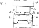
The plunger 18 may be made of glass ceramic, which ensures good insulation between the diaphragm, ie the pressure chamber in which the pressure is to be measured, and the measuring element 19. The end of the plunger 18 facing the tip 20 may be conical. This end can thereby have a diameter approximately equal to the sensitive resistance of the measuring element 19 or can be placed in the center of the diaphragm 34 or Wheatstone bridge circuit. This makes it possible to limit the plunger to the size of the measuring element 19 in the pressure transmission part, despite guiding the plunger 18 in the hole 12. In order to ensure as accurately as possible a defined introduction of force from the plunger 18 to the measuring element 19, the plunger 18 is made of a material whose at least its end region 17 is relatively soft. As a result, it is possible to prevent the surface roughness of the plunger end from occurring as a measurement error in the measurement resistor 21 of the measurement element 19. In this case, a shape connection is obtained between the end face of the plunger end and the surface of the measuring element 19. Here, the intermediate element 36 may be disposed on the chip 20. This intermediate element serves to introduce the force of the plunger 18 into the measuring element 19 very uniformly with a precisely defined mounting surface. In addition, at that time, the measuring element 19 is not broken by the rough and uneven surface of the plunger end, and no additional lateral tension is generated in the measuring element. The intermediate element 36 is advantageously made of borosilicate glass or likewise silicon. This is because these materials are compatible with silicon chips in terms of thermal expansion coefficient and have high surface quality. For borosilicate glass, use Corning-Glass Works (Pyrex) material Pyrex or Schott (Firma Schott, Mainz, Germany) material Tempax. May be. The intermediate element 36 may have a so-called convex structure processed by etching or a mesa structure 32 as shown in FIG. The mesa structure is no longer formed with a flat surface and is provided with protrusions and / or recesses. For example, already in the manufacturing process, wafers with silicon chips and Pyrex wafers or silicon wafers etched into a mesa structure are anodic bonded or directly bonded, i.e., both are mechanically firmly bonded, followed by Can be sawed. Thereby, extremely high position adjustment accuracy of the intermediate element 36 is obtained.
It is also conceivable to manufacture the entire plunger 18 from a soft material. However, this may still have an adverse effect on the rigidity of the plunger 18. When selecting the material of the plunger 18, it is desirable to consider the following points. That is, the plunger should have as little thermal conductivity as possible, so that the measurement signal is not mistaken due to temperature fluctuations or the effects of the temperature itself. For example, glass ceramics have a small thermal conductivity. As a material for the portion 17 of the plunger 18, for example, a relatively soft metal such as Al, brass, Cu, plastic, or the like may be used. The material for this soft region need not be tailored to a low thermal conductivity.
The chip 20 is in direct contact with a receptacle 37 press fitted in the hole 12 or is connected to this receptacle via a support 38. The support body 38 is adapted to prevent different expansion coefficients from acting between the silicon chip 20 and the receiver 37. Silicon or borosilicate glass is advantageously suitable as the support material. In the receptacle 37, a plurality of holes 40 extending substantially parallel to the hole 12 and penetrating therethrough are formed. In these holes 40, an adjustment pin 31a surrounded by an electrically insulating glass compound and a pin 47 for electrical connection are guided. The pins 31a and 47 are connected to the silicon chip 20 via bonding wires 39. The lead wire 48 of the pin 47 is collected in the mouthpiece 49. In order to protect against harmful effects from the environment such as dampness, the sealing compound 50 may be poured into a region where the holes 12 have pins and electrical circuits.