EP0831245B2 - Industrial shock absorber - Google Patents
Industrial shock absorber Download PDFInfo
- Publication number
- EP0831245B2 EP0831245B2 EP97106799A EP97106799A EP0831245B2 EP 0831245 B2 EP0831245 B2 EP 0831245B2 EP 97106799 A EP97106799 A EP 97106799A EP 97106799 A EP97106799 A EP 97106799A EP 0831245 B2 EP0831245 B2 EP 0831245B2
- Authority
- EP
- European Patent Office
- Prior art keywords
- piston
- damping
- housing
- ring
- shaped
- Prior art date
- Legal status (The legal status is an assumption and is not a legal conclusion. Google has not performed a legal analysis and makes no representation as to the accuracy of the status listed.)
- Expired - Lifetime
Links
Images
Classifications
-
- F—MECHANICAL ENGINEERING; LIGHTING; HEATING; WEAPONS; BLASTING
- F16—ENGINEERING ELEMENTS AND UNITS; GENERAL MEASURES FOR PRODUCING AND MAINTAINING EFFECTIVE FUNCTIONING OF MACHINES OR INSTALLATIONS; THERMAL INSULATION IN GENERAL
- F16F—SPRINGS; SHOCK-ABSORBERS; MEANS FOR DAMPING VIBRATION
- F16F9/00—Springs, vibration-dampers, shock-absorbers, or similarly-constructed movement-dampers using a fluid or the equivalent as damping medium
- F16F9/32—Details
- F16F9/3207—Constructional features
- F16F9/3214—Constructional features of pistons
-
- F—MECHANICAL ENGINEERING; LIGHTING; HEATING; WEAPONS; BLASTING
- F16—ENGINEERING ELEMENTS AND UNITS; GENERAL MEASURES FOR PRODUCING AND MAINTAINING EFFECTIVE FUNCTIONING OF MACHINES OR INSTALLATIONS; THERMAL INSULATION IN GENERAL
- F16F—SPRINGS; SHOCK-ABSORBERS; MEANS FOR DAMPING VIBRATION
- F16F9/00—Springs, vibration-dampers, shock-absorbers, or similarly-constructed movement-dampers using a fluid or the equivalent as damping medium
- F16F9/32—Details
- F16F9/48—Arrangements for providing different damping effects at different parts of the stroke
Definitions
- GB-A-249 928 relates to a shock absorber designed as a buffer with one tubular housing, a longitudinally displaceable and sealingly arranged therein pot-shaped damping piston, one through one at one end of the one-piece housing attached bearing bush sealed out to the outside Piston rod is assigned, the damping piston being one or has several throttle bores that penetrate its wall and one Connect the damping space to an annular space surrounding the damping piston, which in turn to one on the back of the damping piston Compensation room can be connected to conduct liquid.
- This buffer in The shape of an oil shock absorber has a one-piece housing that is approximately cup-shaped is formed, the open end being closed by a lid while on the base part a peg-shaped housing set in one piece is arranged, through which a piston rod is led out sealed.
- a cup-shaped piston is arranged at the free, inner end of the piston rod, the open end face of which is the cone-shaped housing approach opposite end portion of the housing which is larger in cross section.
- This housing consists of two housing sections inside different diameters, with the larger diameter housing section the cone-shaped approach is turned.
- the cup-shaped piston has several through holes penetrating it on its bottom, as well as numerous bores that radial its cylindrical walls penetrate.
- radial bores are made during a stroke of the piston successively swept over by the smaller housing section in diameter, which creates a throttling effect, since fewer and fewer holes for outflow of the compressed oil in an annular space surrounding the piston Are available due to the larger diameter of the housing section is formed.
- the piston has in the direction of the piston rod tapering slot recesses, which are also used to throttle the outflow cross-section serve for the compressed oil, so that this too as through the holes in a compensation chamber arranged behind the pistons can flow.
- a plate valve On a diameter passing through the piston End portion of the piston rod, a plate valve is arranged between the inner end face of the piston and a stop can be moved back and forth is and that the holes penetrating the piston crown at Brake stroke closes and opens on the return stroke, so that the brake chamber with the Compensation chamber via the holes in the piston crown connected in the liquid-conducting Connection is established so that the oil in the compensation chamber over these bores, over the throttle bores and over the annular gap in the Brake space can flow out.
- DE-A-36 43 290 relates to a device for determining the path of a piston in a cylinder for hydraulic, pneumatic or hydropneumatic units, such as vibration dampers, gas springs and hydropneumatic suspensions, wherein the piston via a piston rod in one with at least one Damping medium-filled cylinder is arranged axially displaceable, whereby Level measurement as a measuring section an element defining the level range of at least one Hall sensor is provided.
- the piston extending measuring section, consisting of at least part of the Surface of the cylinder, an element defining the level range and at least part of the surface of the piston rod is provided, at least one of the measuring elements arranged at a distance from the cylinder and opposite this is relatively axially movable.
- the elements are magnetically conductive, the spaced Hall sensor on the element opposite side has a permanent magnet.
- The is built in Device in a vibration damper consisting essentially of a cylinder, a piston and a piston with a piston rod. In the cavity of the Cylinder is the damping medium used for vibration damping. Fastening devices are provided for fastening the vibration damper in a vehicle intended. The whole thing serves as suspension for Vehicle wheels (cars).
- a shock absorber for a bicycle fork is previously known from US-A-5,380,026, which consists of telescopically slidable parts against spring pressure and against a damping medium that is caused by bores in a piston can flow out, exists.
- the invention has for its object one with a liquid damping medium working industrial shock absorber to create one at a ratio relatively large diameter of the damping piston to the outer diameter and with a structurally simple structure, simple reproducibility of various Damping curves allowed over a wide temperature range.
- An industrial shock absorber according to the invention can be made up of relatively few individual parts easy and inexpensive to manufacture.
- the housing can be, for example, from of the rod and, for example, two holes for a wrench have on the ground.
- the piston rod can also be made from the rod and have a groove and a shoulder that is turned. Further the pot-shaped piston is manufactured off the shelf, with throttle bores and provided with a check valve bore.
- the warehouse can also Rod are manufactured and glued in during assembly, for example. Also a roll membrane or a closed-pore elastomer Ring holding pressure accumulator can be made off the shelf and needs only to be provided with one or more holes. If one Roll membrane is provided, this serves as a seal, as volume compensation for the piston rod and as a return spring.
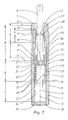
- the reference numeral 1 is a tubular housing made of steel in one piece referred to, for example, made by drilling a rod and thus particularly tight and pressure-resistant is.
- the housing 1 is only open on one end side.
- the bearing bush 2 is sealed from the outside. This takes place in the embodiment according to FIG. 1 by a rolling membrane 3 and in the embodiment according to FIG. 2 by a ring recess in the bearing bush 2 arranged seal 4.
- the seal 4 can also be arranged several times, in particular act as a seal on both sides.
- a seal 5 is in arranged an annular groove.
- the bearing bush 2 overlaps the outwardly directed annular end face 6 with an im Collar 7 enlarged in diameter.
- This collar 7 has a plane parallel to the ring end face 6 Ring surface, so that the bearing bush 2 rests with its collar 7 flat against the ring end face 6.
- a piston rod 8 is longitudinally displaceable in a coaxial to the longitudinal center axis 9 extending bore 10 arranged.
- the housing 1 is on its outer surface 11 in the illustrated embodiments with the same Designed diameter and can be cylindrical. It can also be seen from FIGS. 1 and 2 that the illustrated embodiments at their end section facing away from the piston rod 8 with an external thread for fastening the industrial shock absorber in a device, not shown, for example in a handling device, in a machine tool or the like.
- Both embodiments have two mirror images on the closed end face on the longitudinal center axis 9 arranged blind holes 12 and 13, in which a tool, not shown, is inserted can be.
- the interior of the housing 1 consists of a total of three successive cylindrical surface areas limited housing sections 14, 15 and 16.
- the arrangement is such in the illustrated embodiments taken that the following housing section is reduced in diameter. That means, that the housing section 14 has the largest inner diameter, the subsequent housing section 15 a little smaller diameter and the housing section 16 has the smallest diameter.
- the housing sections 14, 15 and 16 are each continuously cylindrical. Also are all housing sections 14, 15 and 16 arranged coaxially to one another, so that the housing 1 is a cartridge Possesses exterior.
- a cup-shaped damping piston 19 with its closed End face of the housing 1 facing length section on the inner wall of the housing section 16 except for minor Leakages are therefore pressure-tight.
- the damping piston 19 is on his Outer lateral surface 20 of the inner lateral surface of the housing section 16 is adapted. If the inner lateral surface of the housing section 16 is cylindrical except for slight leaks, the outer surface 20 is also cylindrical educated.
- the damping piston 19 is at the closed end portion of the housing 1 facing end face is tubular open, the damping piston 19 on a length section D widens conically outwards.
- the damping piston 19 On its inside, the damping piston 19 is provided with a cylindrical inner surface 21 extends approximately 80% of the total length of the piston.
- the tubular part of the damping piston 19 is through a piston crown 22 in one piece with the tubular longitudinal section of the damping piston 19 connected.
- the damping piston 19 has an annular shoulder which overlaps the outer lateral surface 20 23, with which the damping piston 19 is longitudinally displaceable on the inner lateral surface of the housing section 15 is stored and managed.
- the annular shoulder 23 can have several web-shaped openings or - as shown - with at least one, preferably with several distributed over the circumference, parallel to the longitudinal center axis 9 extending connecting holes 24 may be provided.
- annular space 25 is arranged, which through the openings or connecting bores 24 or the like is connected to a compensation chamber 26 in a liquid-conducting manner.
- the rolling membrane 3 is arranged in the embodiment according to FIG is connected at one end to an annular groove 27 of the piston rod 8 via a bead 28 in a pressure-tight manner.
- the rolling membrane 3 is also connected to an annular groove of a ring 30 via a bead 29, which is penetrated centrally by the piston rod 8.
- the ring 30 is via a seal 31 on the inner wall of the housing section 14 sealed liquid-tight.
- the beads 28, 29 are also designed to be liquid-tight.
- At least one channel 32 is provided in the ring 30, the longitudinal axis of which is parallel to the longitudinal central axis 9 runs.
- the channel 32 connects the compensation space 26 via the connecting bore 24 or the like in the manner to be described with the annular space 25.
- a further through bore 33 is provided in the piston crown 22, which has a damping space 34 in the manner yet to be described, also via the channel 32 with the compensation space 26 combines.
- a reduced diameter pin 35 which on his free end has an annular shoulder 36, with a stop on the pin 35, for example a snap ring 37, is detachably arranged.
- a stop on the pin 35 for example a snap ring 37
- the pin 35 needs it receiving bore of the piston crown 22 not to be arranged liquid-tight.
- the pin is 35 in the through bore of the piston crown 22 by a through the annular shoulder 36 of the piston rod 8 on the one hand and the stop 37, on the other hand, arranged axially displaceable to a limited extent.
- throttle bores 39 which are arranged relative to one another and connect the damping space 34 to the annular space 25.
- These throttle bores 39 are in order in the event of an axial displacement, that is to say during the damping process the relatively sharp-edged ring shoulder 18 painted over and sealed so that when the damping piston is immersed 19 in the damping chamber 34 fewer and fewer throttle bores 39 for the outflow of the throttle fluid into the Annulus 25 and thus via the connecting bore 24 and the channel 32 in the compensation space 26 available stand.
- the through hole 33 is covered by the annular shoulder 36 of the piston rod 8.
- This ring shoulder 36 like the end face of the piston head 22 facing the piston rod 8, runs orthogonal to Longitudinal center axis 9. Both facing end faces of the annular shoulder 36 of the piston rod 8 and the piston crown 22 are plane-parallel and lie until the damping piston 19 lifts off the annular shoulder 36 of the piston rod 8 sealing one another.
- the bearing bush 2 has one on its outer surface relatively long, cylindrical section which fits in the housing section 14 and on the inner wall is applied.
- the bearing bush 2 has a longitudinal section L, the wall of which is limited inside and outside by cylindrical walls and has a relatively small wall thickness. Over the length section L is thus designed to be tubular. A length section adjoins the length section L. K an, which is composed of the collar 7 and a length section reinforced in the wall thickness. This last length section has a conically tapering length section M and a cylindrical length section V on. In the latter, the bead 28 and a part of the rolling membrane 3 is arranged, while in the Length section M and in the length section L the rolling membrane 3 is resilient during the damping process into deformed. The transition from the length section L to the length section M can be made over a radius happen to protect the rolling membrane 3.
- the stop 37 can consist of metallic materials, for example of steel.
- the seals and the roll membrane 3 are each made of age-resistant, ozone-resistant, light-fast and elastomers resistant to the damping liquids used, for example polyurethane rubbers with elastic properties.
- the bearing bush 2 is in the axial longitudinal section shown in the drawing designed approximately double T-shaped, the one web of the double-T materially in one piece with the collar 7 is formed, while at the axial distance from the collar 7, the other web of the double-T is arranged and as Bearing ring flange 40 is formed.
- This bearing ring flange 40 is mounted on the ring shoulder 17.
- the Bearing ring flange is also cylindrical on its outer surface and fits snugly in the length section 14 and lies flat against the inner lateral surface of the housing section 14.
- the compensation space 26 is created in which in the illustrated embodiment, a compensating or receiving element 41 made of an elastic elastomer plastic is arranged.
- the receiving or compensating element 41 is designed as a closed-cell sponge and serves for volume compensation for the retracting piston rod.
- a channel is designated, which has the same function as the channel 32 of the embodiment of FIG. 1.
- the piston rod 8 is arranged in a recess 43 at the end face.
- the piston rod 8 has a shoulder 44 enlarged in diameter, which partly extends axially from the recess 43 in the direction of the damping piston 19 protrudes.
- the recess 43 is arranged coaxially to the longitudinal center axis 9.
- a through hole 45 is provided, which has the same task as the through hole 33. Furthermore, a valve seat 46 is provided in the piston crown 22, to which a shut-off body 47 is assigned is, which is designed as a ball in the present case. So that this ball 47 is not formed in the piston crown 22 Valve chamber 48 can fall out, the edge regions 49 facing the damping chamber 34 are by turning them around or the like flanged, but without closing the flow cross-section.
- compression spring 50 is indicated only a schematically indicated compression spring, which is under tension on her one end against the closed bottom of the housing 1 and with its other end against the piston head 22 supports.
- the compression spring 50 is supported and guided by the cylindrical part of the damping piston 19.
- the compression spring 50 serves the damping piston 19 and the piston rod 8 in the drawn starting position to push.
- the housing 1, the bearing bush 2, the piston rod 8, the damping piston 19 and the shut-off body 47 made of a metallic material, in particular steel.
- FIGS. 1 and 2 show how few individual parts are required for an industrial shock absorber according to the invention and how simple the construction of such embodiments according to the invention is:
- WO 94/17317 invention Total parts 14 8 or 9 Norm or purchased parts 4 2 or 3 Parts to be made 10 6
Description
Die GB-A-249 928 betrifft einen als Prellbock ausgebildeten Stoßdämpfer mit einem rohrförmigen Gehäuse, einem längsverschieblich und dichtend darin angeordneten topfförmigen Dämpfungskolben, dem eine durch eine an einem Ende des einstückigen Gehäuses befestigte Lagerbuchse abgedichtet nach außen herausgeführte Kolbenstange zugeordnet ist, wobei der Dämpfungskolben eine oder mehrere Drosselbohrungen aufweist, die seine Wand durchsetzen und einen Dämpfungsraum mit einem dem Dämpfungskolben umgebenden Ringraum verbinden, der seinerseits an einen auf der Rückseite des Dämpfungskolbens befindlichen Ausgleichsraum flüssigkeitsleitend anschließbar ist. Dieser Prellbock in Form eines Ölstoßdämpfers besitzt ein einstückiges Gehäuse, das etwa topfförmig ausgebildet ist, wobei das offene Ende durch einen Deckel verschlossen ist, während an dem Bodenteil ein zapfenförmiger Gehäusesatz materialmäßig einstückig angeordnet ist, durch den eine Kolbenstange abgedichtet herausgeführt ist. Auf dem freien, inneren Ende der Kolbenstange ist ein topfförmiger Kolben angeordnet, dessen offene Stirnseite sich zu dem dem zapfenförmigen Gehäuseansatz entgegengesetzten Endabschnitt des im Querschnitt größeren Gehäuses erstreckt. Dieses Gehäuse besteht im Inneren aus zwei Gehäuseabschnitten von unterschiedlichen Durchmessern, wobei der im Durchmesser größere Gehäuseabschnitt dem zapfenförmigen Ansatz zugekehrt ist. Der topfförmige Kolben besitzt sowohl an seinem Boden mehrere ihn durchsetzende Durchgangsbohrungen, als auch zahlreiche Bohrungen, die seine zylindrischen Wandungen radial durchdringen. Diese radialen Bohrungen werden bei einem Hub des Kolbens nacheinander von dem im Durchmesser kleineren Gehäuseabschnitt überstrichen, wodurch ein Drosseleffekt entsteht, da immer weniger Bohrungen zur Abströmung des zusammengepreßten Öls in einem den Kolben umgebenden Ringraum zur Verfügung stehen, der durch den im Durchmesser größeren Gehäuseabschnitt gebildet wird. Außerdem besitzt der Kolben sich in Richtung der Kolbenstange verjüngende Schlitzausnehmungen, die ebenfalls zur Drosselung des Abströmquerschnittes für das zusammengepreßte Öl dienen, damit dieses ebenso wie über die Bohrungen in einen hinter den Kolben angeordneten Ausgleichsraum strömen kann. Auf einem den Kolben durchsetzenden, im Durchmesser verringerten Endabschnitt der Kolbenstange ist ein Plattenventil angeordnet, das zwischen der inneren Stirnseite des Kolbens und einem Anschlag hin und her verschiebbar ist und das die den Kolbenboden durchsetzende Bohrungen beim Bremshub verschließt und beim Rückhub öffnet, so daß der Bremsraum mit dem Ausgleichsraum über die im Kolbenboden verbundenen Bohrungen in flüssigkeitsleitender Verbindung steht, so daß das in dem Ausgleichsraum befindliche Öl über diese Bohrungen, über die Drosselbohrungen und über den Ringspalt in den Bremsraum abströmen kann. GB-A-249 928 relates to a shock absorber designed as a buffer with one tubular housing, a longitudinally displaceable and sealingly arranged therein pot-shaped damping piston, one through one at one end of the one-piece housing attached bearing bush sealed out to the outside Piston rod is assigned, the damping piston being one or has several throttle bores that penetrate its wall and one Connect the damping space to an annular space surrounding the damping piston, which in turn to one on the back of the damping piston Compensation room can be connected to conduct liquid. This buffer in The shape of an oil shock absorber has a one-piece housing that is approximately cup-shaped is formed, the open end being closed by a lid while on the base part a peg-shaped housing set in one piece is arranged, through which a piston rod is led out sealed. On a cup-shaped piston is arranged at the free, inner end of the piston rod, the open end face of which is the cone-shaped housing approach opposite end portion of the housing which is larger in cross section. This housing consists of two housing sections inside different diameters, with the larger diameter housing section the cone-shaped approach is turned. The cup-shaped piston has several through holes penetrating it on its bottom, as well as numerous bores that radial its cylindrical walls penetrate. These radial bores are made during a stroke of the piston successively swept over by the smaller housing section in diameter, which creates a throttling effect, since fewer and fewer holes for outflow of the compressed oil in an annular space surrounding the piston Are available due to the larger diameter of the housing section is formed. In addition, the piston has in the direction of the piston rod tapering slot recesses, which are also used to throttle the outflow cross-section serve for the compressed oil, so that this too as through the holes in a compensation chamber arranged behind the pistons can flow. On a diameter passing through the piston End portion of the piston rod, a plate valve is arranged between the inner end face of the piston and a stop can be moved back and forth is and that the holes penetrating the piston crown at Brake stroke closes and opens on the return stroke, so that the brake chamber with the Compensation chamber via the holes in the piston crown connected in the liquid-conducting Connection is established so that the oil in the compensation chamber over these bores, over the throttle bores and over the annular gap in the Brake space can flow out.
Die DE-A-36 43 290 betrifft eine Vorrichtung zur Wegbestimmung eines Kolbens in einem Zylinder für hydraulische, pneumatische oder hydropneumatische Aggregate, wie Schwingungsdämpfer, Gasfedern und hydropneumatische Federungen, wobei der Kolben über eine Kolbenstange in einem mit mindestens einem Dämpfungsmittel gefüllten Zylinder axial verschiebbar angeordnet ist, wobei zur Niveaumessung als Meßstrecke ein den Niveaubereich festlegendes Element von mindestens einem Hallsensor vorgesehen ist. Es ist eine über den gesamten Hub des Kolbens verlaufende Meßstrecke, bestehend aus mindestens einem Teil der Oberfläche des Zylinders, einem den Niveaubereich festlegenden Elementes und mindestens einem Teil der Oberfläche der Kolbenstange vorgesehen, wobei mindestens eines der Meßelemente im Abstand zum Zylinder angeordnet und gegenüber diesem relativ axial bewegbar ist. Die Elemente sind magnetisch leitfähig, wobei der im Abstand angeordnete Hallsensor auf der dem Element entgegengesetzten Seite einen Permanentmagneten aufweist. Eingebaut ist die Vorrichtung in einem Schwingungsdämpfer, der im wesentlichen aus einem Zylinder, einem Kolben und einem Kolben mit Kolbenstange besteht. Im Hohlraum des Zylinders befindet sich das der Schwingungsdämpfung dienende Dämpfungsmedium. Zur Befestigung des Schwingungsdämpfers in einem Fahrzeug sind Befestigungsvorrichtungen vorgesehen. Das Ganze dient somit als Federung für Fahrzeugräder (PKW).DE-A-36 43 290 relates to a device for determining the path of a piston in a cylinder for hydraulic, pneumatic or hydropneumatic units, such as vibration dampers, gas springs and hydropneumatic suspensions, wherein the piston via a piston rod in one with at least one Damping medium-filled cylinder is arranged axially displaceable, whereby Level measurement as a measuring section an element defining the level range of at least one Hall sensor is provided. It is one across the entire hub of the piston extending measuring section, consisting of at least part of the Surface of the cylinder, an element defining the level range and at least part of the surface of the piston rod is provided, at least one of the measuring elements arranged at a distance from the cylinder and opposite this is relatively axially movable. The elements are magnetically conductive, the spaced Hall sensor on the element opposite side has a permanent magnet. The is built in Device in a vibration damper consisting essentially of a cylinder, a piston and a piston with a piston rod. In the cavity of the Cylinder is the damping medium used for vibration damping. Fastening devices are provided for fastening the vibration damper in a vehicle intended. The whole thing serves as suspension for Vehicle wheels (cars).
Aus der US-A-5,380,026 ist ein Stoßdämpfer für eine Fahrradgabel vorbekannt, der aus teleskopförmig ineinander verschiebbaren Teilen besteht, die gegen Federdruck und gegen ein Dämpfungsmedium, das durch Bohrungen eines Kolbens abströmen kann, besteht.A shock absorber for a bicycle fork is previously known from US-A-5,380,026, which consists of telescopically slidable parts against spring pressure and against a damping medium that is caused by bores in a piston can flow out, exists.
Der Erfindung liegt die Aufgabe zugrunde, einen mit einem flüssigen Dämpfungsmedium arbeitenden Industrie-Stoßdämpfer zu schaffen, der bei einem im Verhältnis zum Außendurchmesser relativ großen Durchmesser des Dämpfungskolbens und bei konstruktiv einfachem Aufbau eine einfache Reproduzierbarkeit verschiedener Dämpfungskurven über einen großen Temperaturbereich gestattet.The invention has for its object one with a liquid damping medium working industrial shock absorber to create one at a ratio relatively large diameter of the damping piston to the outer diameter and with a structurally simple structure, simple reproducibility of various Damping curves allowed over a wide temperature range.
Die Aufgabe wird durch die in Patentanspruch 1 wiedergegebenen Merkmale
gelöst. The object is achieved by the features set out in
Ein erfindungsgemäßer Industrie-Stoßdämpfer läßt sich aus relativ wenigen Einzelteilen einfach und preisgünstig fertigen. Das Gehäuse kann zum Beispiel von der Stange gefertigt werden und zum Beispiel zwei Bohrungen für einen Stiftschlüssel am Boden aufweisen. Auch die Kolbenstange kann von der Stange gefertigt werden und eine Nut und einen Absatz aufweisen, der angedreht wird. Ferner wird der topfförmige Kolben von der Stange gefertigt, mit Drosselbohrungen und mit einer Rückschlagventilbohrung versehen. Auch das Lager kann von der Stange gefertigt werden und bei der Montage zum Beispiel eingeklebt werden. Auch eine Rollmembran oder ein aus geschlossenporigem Elastomer bestehender Druckspeicher haltender Ring kann von der Stange gefertigt werden und braucht lediglich mit einer oder mehreren Bohrungen versehen zu werden. Sofern eine Rollmembran vorgesehen wird, dient diese als Dichtung, als Volumenausgleich für die Kolbenstange und als Rückstellfeder.An industrial shock absorber according to the invention can be made up of relatively few individual parts easy and inexpensive to manufacture. The housing can be, for example, from of the rod and, for example, two holes for a wrench have on the ground. The piston rod can also be made from the rod and have a groove and a shoulder that is turned. Further the pot-shaped piston is manufactured off the shelf, with throttle bores and provided with a check valve bore. The warehouse can also Rod are manufactured and glued in during assembly, for example. Also a roll membrane or a closed-pore elastomer Ring holding pressure accumulator can be made off the shelf and needs only to be provided with one or more holes. If one Roll membrane is provided, this serves as a seal, as volume compensation for the piston rod and as a return spring.
Bei solchen Ausführungsformen, die einen Druckspeicher oder Absorber aufweisen, der aus einem geschlossenporigen Elastomer bestehen, dient dieser als Volumenausgleich beim Einfahren der Kolbenstange.In those embodiments which have a pressure accumulator or absorber, which consist of a closed-pore elastomer, this serves as volume compensation when retracting the piston rod.
Weitere erfinderische Ausführungsformen sind in den Patentansprüchen 2 bis 6
beschrieben. Further inventive embodiments are described in
In der Zeichnung ist die Erfindung - teils schematisch - an zwei Ausführungsbeispielen im Längsschnitt veranschaulicht. Es zeigen:
- Fig. 1
- einen Industrie-Stoßdämpfer mit einer Rollmembran;
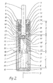
- Fig. 2
- einen ähnlich aufgebauten Industrie-Stoßdämpfer mit einem Elastomer-Druckspeicher.
- Fig. 1
- an industrial shock absorber with a rolling membrane;
- Fig. 2
- a similarly constructed industrial shock absorber with an elastomer pressure accumulator.
Mit den Bezugszeichen 1 ist ein materialmäßig einstückiges, aus Stahl bestehendes, rohrförmiges Gehäuse
bezeichnet, das zum Beispiel durch Aufbohren einer Stange hergestellt und dadurch besonders dicht und druckfest
ist. Das Gehäuse 1 ist nur an einer Stimseite offen ausgebildet. In die offene Mündungsöffnung ist eine Lagerbuchse
2 angeordnet, zum Beispiel eingeklebt, eingeschraubt oder in sonstiger Weise fest, aber lösbar, in dem Gehäuse 1
befestigt. Die Lagerbuchse 2 ist nach außen hin abgedichtet. Dies geschieht bei der Ausführungsform nach Fig. 1
durch eine Rollmembran 3 und bei der Ausführungsform nach Fig. 2 durch eine in einer Ringaussparung der Lagerbuchse
2 angeordnete Dichtung 4. Die Dichtung 4 kann im Bedarfsfall auch mehrfach angeordnet sein, insbesondere
nach beiden Seiten hin abdichtend wirken. Des weiteren ist bei der Ausführungsform nach Fig. 2 eine Dichtung 5 in
einer Ringnut angeordnet.With the
Wie man erkennt, übergreift die Lagerbuchse 2 die nach außen gerichtete Ringstirnfläche 6 mit einem im
Durchmesser vergrößerten Kragen 7. Dieser Kragen 7 besitzt eine planparallel zu der Ringstirnfläche 6 verlaufende
Ringfläche, so daß die Lagerbuchse 2 mit ihrem Kragen 7 flächig an der Ringstirnfläche 6 anliegt.As can be seen, the
In der Lagerbuchse 2 ist eine Kolbenstange 8 längsverschieblich in einer koaxial zur Längsmittenachse 9
verlaufenden Bohrung 10 angeordnet.In the
Das Gehäuse 1 ist an seiner Außenmantelfläche 11 bei den dargestellten Ausführungsformen mit gleichem
Durchmesser ausgestaltet und kann zylindrisch ausgebildet sein. Außerdem erkennt man aus den Fig. 1 und 2, daß
die dargestellten Ausführungsformen an ihrem der Kolbenstange 8 abgewandten Endabschnitt mit Außengewinde
zum Befestigen des Industrie-Stoßdämpfers in einer nicht dargestellten Vorrichtung, zum Beispiel in einem Handhabungsgerät,
in einer Werkzeugmaschine oder dergleichen, versehen sind.The
Beide Ausführungsformen besitzen an der geschlossen ausgebildeten Stirnseite zwei spiegelbildlich in Bezug
auf die Längsmittenachse 9 angeordnete Sackbohrungen 12 bzw. 13, in die ein nicht dargestelltes Werkzeug eingesetzt
werden kann.Both embodiments have two mirror images on the closed end face
on the
Das Gehäuse 1 besteht in seinem Inneren aus insgesamt drei aufeinanderfolgende, durch zylindrische Mantelflächen
begrenzte Gehäuseabschnitte 14, 15 und 16. Die Anordnung ist derart bei den dargestellten Ausführungsformen
getroffen worden, daß der jeweils folgende Gehäuseabschnitt sich im Durchmesser verkleinert. Das bedeutet,
daß der Gehäuseabschnitt 14 den größten Innendurchmesser, der darauffolgende Gehäuseabschnitt 15 einen etwas
kleineren Durchmesser und der Gehäuseabschnitt 16 den kleinsten Durchmesser aufweist. Über ihre jeweilige Länge
A, B bzw. C sind die Gehäuseabschnitte 14, 15 und 16 jeweils durchgehend zylindrisch ausgebildet. Außerdem sind
sämtliche Gehäuseabschnitte 14, 15 und 16 koaxial zueinander angeordnet, so daß das Gehäuse 1 ein patronenförmiges
Äußeres besitzt.The interior of the
Durch die Unterteilung des Gehäuses 1 in den drei Gehäuseabschnitten 14, 15 und 16 mit jeweils unterschiedlichem
Innendurchmesser ergeben sich jeweils an dem Übergang zu dem folgenden Gehäuseabschnitt, also
von 14 auf 15 und von dem Gehäuseabschnitt 15 auf 16 eine nach innen hervorragende, relativ scharfkantige Ringschulter
17 bzw. 18.By dividing the
Wie aus der Zeichnung hervorgeht, ist ein topfförmiger Dämpfungskolben 19 mit seinem der geschlossenen
Stirnseite des Gehäuses 1 zugekehrten Längenabschnitt an der Innenwand des Gehäuseabschnittes 16 bis auf geringfügige
Leckagen also möglichst druckmitteldicht geführt. Zu diesem Zweck ist der Dämpfungskolben 19 an seiner
Außenmantelfläche 20 der Innenmantelfläche des Gehäuseabschnittes 16 angepaßt. Wenn die Innenmantelfläche
des Gehäuseabschnittes 16 bis auf geringfügige Leckagen zylindrisch ist, ist auch die Außenmantelfläche 20 zylinderförmig
ausgebildet.As can be seen from the drawing, a cup-
Bei sämtlichen Ausführungsformen ist der Dämpfungskolben 19 an seiner dem geschlossenen Endabschnitt
des Gehäuses 1 zugekehrten Stimseite rohrförmig offen ausgebildet, wobei der Dämpfungskolben 19 auf einem Längenabschnitt
D sich konisch nach außen hin erweitert.In all embodiments, the
An seiner Innenseite ist der Dämpfungskolben 19 mit einer zylindrischen Innenmantelfläche 21 versehen, die
sich etwa über 80 % der Gesamtlänge des Kolbens erstreckt. Der rohrförmige Teil des Dämpfungskolbens 19 ist durch
einen Kolbenboden 22 materialmäßig einstückig mit dem rohrförmigen Längenabschnitt des Dämpfungskolbens 19
verbunden. In diesem Bereich weist der Dämpfungskolben 19 eine die Außenmantelfläche 20 übergreifende Ringschulter
23 auf, mit der der Dämpfungskolben 19 an der Innenmantelfläche des Gehäuseabschnittes 15 längsverschieblich
gelagert und geführt ist. Die Ringschulter 23 kann mit mehreren stegförmigen Durchbrechungen oder - wie
dargestellt - mit mindestens einer, vorzugsweise mit mehreren über den Umfang verteilten, parallel zur Längsmittenachse
9 verlaufenden Verbindungsbohrungen 24 versehen sein.On its inside, the
Zwischen der Außenmantelfläche 20 des Dämpfungskolbens 19 und der Innenmantelfläche des Gehäuseabschnittes
15 ist ein Ringraum 25 angeordnet, der über die Durchbrechungen bzw. Verbindungsbohrungen 24 oder
dergleichen mit einem Ausgleichsraum 26 flüssigkeitsleitend verbunden ist.Between the
In diesem Ausgleichsraum 26 ist bei der Ausführungsform nach Fig. 1 die Rollmembran 3 angeordnet, die
an ihrem einen Ende mit einer Ringnut 27 der Kolbenstange 8 über einen Wulst 28 druckmitteldicht verbunden ist. An
ihrem anderen Ende ist die Rollmembran 3, ebenfalls über eine Wulst 29 mit einer Ringnut eines Ringes 30 verbunden,
der von der Kolbenstange 8 zentrisch durchdrungen wird. Der Ring 30 ist über eine Dichtung 31 an der Innenwand
des Gehäuseabschnittes 14 flüssigkeitsdicht abgedichtet. Auch die Wulste 28, 29 sind flüssigkeitsdicht ausgebildet.In this
In dem Ring 30 ist mindestens ein Kanal 32 vorgesehen, dessen Längsachse parallel zur Längsmittenachse
9 verläuft. Der Kanal 32 verbindet den Ausgleichsraum 26 über die Verbindungsbohrung 24 oder dergleichen in der
noch zu beschreibenden Art und Weise mit dem Ringraum 25.At least one
Außerdem ist im Kolbenboden 22 eine weitere Durchgangsbohrung 33 vorgesehen, die einen Dämpfungsraum
34 in der noch zu beschreibenden Art und Weise über den Kanal 32 ebenfalls mit dem Ausgleichsraum 26
verbindet.In addition, a further through
Mit der Kolbenstange 8 ist einstückig ein im Durchmesser verringerter Zapfen 35 verbunden, der an seinem
freien Ende eine Ringschulter 36 aufweist, wobei an dem Zapfen 35 ein Anschlag, zum Beispiel ein Sprengring 37,
lösbar angeordnet ist. Wie man aus Fig. 1 erkennt, ist in der ersichtlichen Ausgangsstellung zwischen der Innenseite
38 des Kolbenbodens 22 und dem Anschlag 37 ein gewisses Spiel vorhanden. Der Zapfen 35 braucht in der ihn
aufnehmenden Bohrung des Kolbenbodens 22 nicht flüssigkeitsdicht angeordnet zu sein. Allerdings ist der Zapfen 35
in der Durchgangsbohrung des Kolbenbodens 22 um ein durch die Ringschulter 36 der Kolbenstange 8 einerseits und
den Anschlag 37 andererseits begrenztes axiales Maß längsverschieblich angeordnet.With the
Des weiteren erkennt man aus Fig. 1, daß der Dämpfungskolben 19 an seiner einen Seite mehrere parallel
zueinander angeordnete Drosselbohrungen 39 aufweist, die den Dämpfungsraum 34 mit dem Ringraum 25 verbinden.
Diese Drosselbohrungen 39 werden bei einer Axialverschiebung, also beim Dämpfungsvorgang, der Reihe nach durch
die relativ scharfkantige Ringschulter 18 überstrichen und abgedichtet, so daß beim Eintauchen des Dämpfungskolbens
19 in den Dämpfungsraum 34 immer weniger Drosselbohrungen 39 zum Abströmen der Drosselflüssigkeit in den
Ringraum 25 und damit über die Verbindungsbohrung 24 und den Kanal 32 in den Ausgleichsraum 26 zur Verfügung
stehen.1 that the damping
Beim Eintauchen des Dämpfungskolbens 19, also beim Dämpfungsvorgang, wird die orthogonal zur Längsmittenachse
9 verlaufende, dem Ring 30 zugekehrte planparallele Stirnseite des Dämpfungskolbens 19 von der ebenso
ausgebildeten planparallelen Stirnseite des Ringes 30 abgehoben, so daß Dämpfungsflüssigkeit durch die Drosselbohrung
39 in den Ringraum 25, die Verbindungsbohrung 24 und den Kanal 32 in den Ausgleichsraum 26 austreten
kann, wobei die Rollmembran 3 unter federelastischer Spannung versetzt wird, so daß sie später beim Zurückführen
des Stoßdämpfers in seine Ausgangslage wie ein Federelement unterstützend wirkt.When the damping
Die Durchgangsbohrung 33 ist hierbei von der Ringschulter 36 der Kolbenstange 8 abgedeckt. Diese Ringschulter
36 verläuft ebenso wie die der Kolbenstange 8 zugekehrte Stirnfläche des Kolbenbodens 22 orthogonal zur
Längsmittenachse 9. Beide einander zugekehrten Stirnflächen der Ringschulter 36 der Kolbenstange 8 und des Kolbenbodens
22 sind planparallel ausgebildet und liegen bis zum Abheben des Dämpfungskolbens 19 von der Ringschulter
36 der Kolbenstange 8 dichtend aufeinander.The through
Die Lagerbuchse 2 besitzt bei der aus Fig. 1 ersichtlichen Ausführungsform einen an ihrer Außenmantelfläche
relativ langen, zylindrischen Abschnitt, der passend in den Gehäuseabschnitt 14 eingreift und an dessen Innenwandung
anliegt.In the embodiment shown in FIG. 1, the bearing
Zur Bildung des Ausgleichsraumes 26 weist die Lagerbuchse 2 einen Längenabschnitt L auf, dessen Wand
innen und außen durch zylindrische Wände begrenzt ist und eine relativ geringe Wandstärke besitzt. Über den Längenabschnitt
L ist somit die Lagerbuchse 2 rohrförmig gestaltet. An den Längenabschnitt L schließt sich ein Längenabschnitt
K an, der sich aus dem Kragen 7 und einem in der Wanddicke verstärkten Längenabschnitt zusammensetzt.
Dieser letzte Längenabschnitt weist einen konisch sich verjüngenden Längenabschnitt M und einen zylindrischen Längenabschnitt
V auf. In letzterem ist die Wulst 28 und ein Teil der Rollmembran 3 angeordnet, während sich in den
Längenabschnitt M und in den Längenabschnitt L die Rollmembran 3 während des Dämpfungsvorganges federelastisch
hineinverformt. Der Übergang von dem Längenabschnitt L zum Längenabschnitt M kann über einen Radius
geschehen, um die Rollmembran 3 zu schonen.To form the
Wird ein Impuls auf die Kolbenstange 8 und/oder das Gehäuse 1 ausgeübt, dann schieben sich diese Teile
teleskopförmig ineinander, wobei der Dämpfungskolben 19 in den Dämpfungsraum 34 eintaucht und seine Drosselbohrungen
39 der Reihe nach durch die Innenwand des Gehäuseabschnittes 16 möglichst flüssigkeitsdicht abgedichtet
werden.If an impulse is exerted on the
Nach dem Abbremsen der Masse bewirkt die unter Spannung stehende Rollmembran 3, die aus einem Elastomer
bestehen kann, die Rückstellung der Teleskopteile. In diesem Falle hebt sich die Ringschulter 36 der Kolbenstange
8 von der Stirnseite des Kolbenbodens 22 ab, so daß auch die Durchgangsbohrung 33 geöffnet wird. Die
Verschiebung der Kolbenstange 8 gegenüber den Dämpfungskolben 19 dauert so lange, bis der Anschlag 37 an der
inneren Stirnseite des Dämpfungskolbens 19 anstößt. Die Ringschulter 36 der Kolbenstange 8 und die Durchgangsbohrung
33 bilden also ein Rückschlagventil. Auf diese Weise vermag dann die im Ausgleichsraum 26 gespeicherte
Flüssigkeitsmenge durch den Kanal 32 und durch die Durchgangsbohrung 33 wieder in den Dämpfungsraum 34 abzufließen.
Ein Teil der Dämpfungsflüssigkeit tritt auch über die Verbindungsbohrung 24 oder dergleichen und die Drosselbohrungen
39 in den Dämpfungsraum 34 ein, bis der Industrie-Stoßdämpfer seine aus Fig. 1 ersichtliche Ausgangsstellung
erreicht hat.After braking the mass causes the tensioned rolling
Nicht nur das Gehäuse 1, die Lagerbuchse 2, die Kolbenstange 8, der Ring 30 und der Dämpfungskolben
19, sondern auch der Anschlag 37 können aus metallischen Werkstoffen, zum Beispiel aus Stahl, bestehen.Not only the
Die Dichtungen und die Rollmembran 3 sind aus jeweils alterungsbeständigen, ozonbeständigen, lichtechten
und gegen die eingesetzten Dämpfungsflüssigkeiten resistenten Elastomeren, zum Beispiel Polyurethankautschuken
mit federelastischen Eigenschaften, hergestellt.The seals and the
Bei der Ausführungsform nach Fig. 2 ist die Lagerbuchse 2 in dem aus der Zeichnung ersichtlichen Axiallängsschnitt
etwa doppel T-förmig gestaltet, wobei der eine Steg des Doppel-T materialmäßig einstückig mit den Kragen
7 ausgebildet ist, während im axialen Abstand zu dem Kragen 7 der andere Steg des Doppel-T angeordnet und als
Lagerringflansch 40 ausgebildet ist. Dieser Lagerringflansch 40 ist auf der Ringschulter 17 gelagert. Im übrigen ist der
Lagerringflansch an seiner äußeren Mantelfläche ebenfalls zylindrisch ausgebildet und paßt satt in den Längenabschnitt
14 hinein und liegt an der Innenmantelfläche des Gehäuseabschnittes 14 flächig an.In the embodiment according to FIG. 2, the bearing
Zwischen der Ringschulter 17 und dem Lagerringflansch 40 ist der Ausgleichsraum 26 geschaffen, in dem
bei der dargestellten Ausführungsform ein Ausgleichs- oder Aufnahmeelement 41 aus einem elastischen ElastomerKunststoff
angeordnet ist. Das Aufnahme oder Ausgleichselement 41 ist als geschlossenporiger Schwamm ausgebildet
und dient zum Volumenausgleich für die einfahrende Kolbenstange.Between the
Mit 42 ist ein Kanal bezeichnet, der die gleiche Funktion hat, wie der Kanal 32 der Ausführungsform der Fig.
1. Die Kolbenstange 8 ist in einer endstirnseitigen Vertiefung 43 angeordnet. Hierzu besitzt die Kolbenstange 8 eine
im Durchmesser vergrößerte Schulter 44, die zum Teil aus der Vertiefung 43 axial in Richtung auf den Dämpfungskolben
19 herausragt. Die Vertiefung 43 ist koaxial zur Längsmittenachse 9 angeordnet.With 42 a channel is designated, which has the same function as the
Im Kolbenboden 22 ist eine Durchgangsbohrung 45 vorgesehen, die die gleiche Aufgabe hat wie die Durchgangsbohrung
33. Des weiteren ist im Kolbenboden 22 ein Ventilsitz 46 vorgesehen, dem ein Absperrkörper 47 zugeordnet
ist, der vorliegend als Kugel ausgebildet ist. Damit diese Kugel 47 nicht aus der im Kolbenboden 22 gebildeten
Ventilkammer 48 herausfallen kann, sind die dem Dämpfungsraum 34 zugekehrten Randbereiche 49 durch Umstemmen
oder dergleichen umgebördelt, ohne allerdings den Strömungsquerschnitt zu verschließen.In the
Mit 50 ist eine nur schematisch angedeutete Druckfeder bezeichnet, die sich unter Vorspannung an ihrem
einen Ende gegen den geschlossenen Boden des Gehäuses 1 und mit ihrem anderen Ende gegen den Kolbenboden
22 abstützt. Die Druckfeder 50 wird durch den zylindrischen Teil des Dämpfungskolbens 19 mit gelagert und geführt.
Die Druckfeder 50 dient dazu, den Dämpfungskolben 19 und die Kolbenstange 8 in die gezeichnet Ausgangsstellung
zu schieben.With 50 is indicated only a schematically indicated compression spring, which is under tension on her
one end against the closed bottom of the
Die Wirkungsweise der Drosselbohrungen 39 ist die gleiche wie im Zusammenhang mit Fig. 1 beschrieben.The operation of the throttle bores 39 is the same as described in connection with FIG. 1.
An dem der Kolbenstange 8 zugekehrten Endbereich sind mindestens zwei sich rechtwinklig kreuzende, etwa
halbkreisförmige Bohrungen oder Kanäle 51 bzw. 52 angeordnet, so daß beim Rückführen der Teleskopteile Dämpfungsflüssigkeit
aus dem Ausgleichsraum 26 über das Rückschlagventil, also an dem Absperrkörper 47 vorbei, in den
Dämpfungsraum 34 hineinfließen kann.At the end area facing the
Auch bei dieser Ausführungsform bestehen wiederum das Gehäuse 1, die Lagerbuchse 2, die Kolbenstange
8, der Dämpfungskolben 19 sowie der Absperrkörper 47 aus einem metallischen Werkstoff, insbesondere aus Stahl. In this embodiment, too, there are again the
Durch einen Vergleich der WO 94/17317 mit den aus Fig. 1 und 2 ersichtlichen Ausführungsformen gemäß
der Erfindung läßt sich erkennen, wie wenige Einzelteile für einen erfindungsgemäßen Industrie-Stoßdämpfer benötigt
werden und wie einfach der Aufbau solcher erfindungsgemäßer Ausführungsformen ist:
Die in der Zusammenfassung, in den Patentansprüchen und in der Beschreibung beschriebenen sowie aus der Zeichnung ersichtlichen Merkmale können sowohl einzeln als auch in beliebigen Kombinationen für die Verwirklichung der Erfindung wesentlich sein.The described in the abstract, in the claims and in the description and from The visible features of the drawing can be used both individually and in any combination for the realization the invention be essential.
Claims (6)
- Industrial shock absorber with a tubular housing (1), a cup-shaped damping piston (19) which is arranged inside the tubular housing (1) so as to be longitudinally displaceable and to form a seal and to which damping piston (19) is assigned a piston rod (8) extending to the outside and running through a bearing bush (2) fastened to one end of the one-piece housing (1) and sealed and in which shock absorber the damping piston (19) incorporates one or more flow control holes (39) through its wall and connecting a damping chamber (34) with a ring-shaped chamber (25) surrounding the damping piston (19) which ring-shaped chamber (25) in turn can be connected to a compensating chamber (26) arranged on the rear side of the damping piston (19) so as to enable fluid to flow between the chambers, characterised in that the flow control hole or holes (39) through an inner wall of the housing (1) can be covered or closed by axial displacement of the damping piston (19) and in that a non-return valve (33, 36, 37 or 45, 47, 48 respectively) which during the return stroke of the damping piston (19) creates a fluid-conducting connection between the damping chamber (34) and the compensating chamber (26) is assigned to the piston head (22) and in that the wall of the housing (1) closing the flow control hole (39) incorporates a relatively sharp-edged ring-shaped shoulder (18) of the housing (1) and in that the ring-shaped shoulder (18) moves steplessly over a number of flow control holes arranged one behind the other in the longitudinal direction of the damping piston (19) and covers or blocks the flow control holes in the direction of damping and in which shock absorber the damping piston (19) is longitudinally displaceably guided by a ring-shaped shoulder (23) assigned to the piston head (22) in a housing portion (15) with a larger diameter and located opposite the end housing portion (16) into which the damping piston (19) slides during its damping stroke and in that the piston head incorporates at least one connecting hole (24) arranged on one side which connecting hole connects the ring-shaped chamber (25) - if necessary indirectly - to the compensating chamber (26) so as to enable fluid to flow between the chambers and in that the tubular housing (1) is constructed outside as a cylinder and inside of three housing portions (14, 15, 16) separated from one another by ring-shaped shoulders (17, 18) such that the diameters of the housing portions (14, 15, 16) progressively diminish from the housing portion (14) containing the piston rod (18) to the housing portion (16) in which the damping piston (19) with its flow control holes (39) slides and in that the effective surface of the damping piston (19) is constructed only slightly smaller than the cross-section of the housing (1) and in that the housing (1) and the damping piston (19) can be manufactured from steel by drilling from solid bar material and in that the housing (1), the piston rod (8), the compensating chamber (26) and the non-return valve (33, 36, 37 or 45, 47, 48 respectively), the damping piston (19) and any compression spring (50) braced under pretension against the housing (1) on the one hand and in the cup-shaped damping piston (19) on the other are arranged coaxially.
- Shock absorber in accordance with claim 1, characterised in that the piston rod (8) incorporates a solid extension piece (35) of a smaller diameter the length of which extension piece (35) is greater than the thickness of the piston head (22) measured in the axial direction and in that the extension piece (35) runs through a central hole in the piston head (22) and in that the extension piece incorporates at a distance from its free end a stop (37) which is arranged to allow the extension piece to move freely in the axial direction of the surface of the piston head (22) facing the extension piece so that the piston head (22) can be displaced a certain distance along the extension piece (35) and in which shock absorber the piston head (22) and the piston rod (8) are bounded in the area of transition to the extension piece (35) by flat surfaces running at right angles to the longitudinal middle axis (9) of the shock absorber by the whole of which flat surfaces the piston head and the piston rod lie one against the other and close a through-hole (33) during the damping stroke.
- Shock absorber in accordance with claim 1 or 2, characterised in that a valve chamber (48) to which a blocking element (47) is assigned is arranged in the piston head (22) and in that the valve chamber (48) is connected to one or more channels (51, 52) by a through-hole (45) so as to enable fluid to flow.
- Shock absorber in accordance with claim 1 or one of the claims following it, characterised in that the flow control holes (39) are evenly distributed over the circumference of the damping piston (19).
- Shock absorber in accordance with claim 1 or one of the claims following it, characterised in that the cup seal (3) is connected by a thickened edge (28) to the piston rod (8) in a compensating chamber (26) on the one hand and by a thickened edge (29) to a ring-shaped piece (30) on the other hand so as to form a fluidtight seal and in that the ring-shaped piece (30) which is sealed in the housing portion (14) with the largest diameter is retained on the ring-shaped shoulder (17) radially by the inner walling of the housing portion (14) with the largest diameter and axially by the ring-shaped shoulder (17) of this housing portion (14) and by a tubular portion (53) of the bearing bush (2) and in that the ring-shaped piece (30) incorporates a channel (32) which can be connected to the ring-shaped chamber (25) by the connecting hole (24) and in that the cup seal (3) serves as a seal for volume compensation and as a restoring spring for the damping piston (19).
- Shock absorber in accordance with claim 5, characterised in that the cup seal (3) when inserted into the pressure chamber of a compressed-air cylinder generates an additional force component to move back the piston rod (8) and the damping piston (19) when pressure is applied.
Applications Claiming Priority (2)
| Application Number | Priority Date | Filing Date | Title |
|---|---|---|---|
| DE19634092 | 1996-08-23 | ||
| DE19634092 | 1996-08-23 |
Publications (4)
| Publication Number | Publication Date |
|---|---|
| EP0831245A2 EP0831245A2 (en) | 1998-03-25 |
| EP0831245A3 EP0831245A3 (en) | 1998-08-12 |
| EP0831245B1 EP0831245B1 (en) | 1999-09-01 |
| EP0831245B2 true EP0831245B2 (en) | 2003-04-02 |
Family
ID=7803494
Family Applications (1)
| Application Number | Title | Priority Date | Filing Date |
|---|---|---|---|
| EP97106799A Expired - Lifetime EP0831245B2 (en) | 1996-08-23 | 1997-04-24 | Industrial shock absorber |
Country Status (3)
| Country | Link |
|---|---|
| US (1) | US6006873A (en) |
| EP (1) | EP0831245B2 (en) |
| DE (1) | DE59700385D1 (en) |
Families Citing this family (17)
| Publication number | Priority date | Publication date | Assignee | Title |
|---|---|---|---|---|
| DE20010282U1 (en) * | 2000-06-08 | 2000-08-31 | Salice Arturo Spa | Device for damping impacts, preferably the impacts of furniture doors or drawers |
| ES2238516T3 (en) * | 2001-05-17 | 2005-09-01 | Julius Blum Gmbh | SHOCK ABSORBER, ESPECIALLY FOR FURNITURE. |
| US6464052B1 (en) * | 2002-02-13 | 2002-10-15 | Chun-Sung Hsiao | Rotatable hydraulic damper |
| DE20210295U1 (en) * | 2002-07-03 | 2002-09-05 | Salice Arturo Spa | Device for damping impacts, preferably the impacts of furniture doors or drawers |
| US7320388B2 (en) * | 2003-09-15 | 2008-01-22 | Tenneco Automotive Operating Company Inc. | Stroke dependent damping |
| US7270317B2 (en) * | 2004-10-28 | 2007-09-18 | Bfs Diversified Products, Llc | Fluid suspension member having grooved inlet |
| JP5100150B2 (en) * | 2006-03-02 | 2012-12-19 | 株式会社コガネイ | shock absorber |
| JP4517373B2 (en) * | 2007-06-27 | 2010-08-04 | Smc株式会社 | shock absorber |
| DE102008040984A1 (en) * | 2007-08-28 | 2009-03-05 | Zf Friedrichshafen Ag | Protective tube for a piston-cylinder unit |
| US8066265B2 (en) * | 2008-10-31 | 2011-11-29 | Firestone Industrial Products Company, Llc | Gas suspension member and method |
| DE202012004636U1 (en) * | 2012-05-10 | 2013-08-12 | Intorq Gmbh & Co. Kg | Damper element and brake with damper elements |
| CN103352958B (en) * | 2013-07-02 | 2016-03-23 | 太原理工大学 | A kind of hydraulic pressure cylinder cushion |
| DE102016118184B3 (en) * | 2016-09-27 | 2017-10-26 | Sartorius Lab Instruments Gmbh & Co. Kg | Use of a hydraulic shock absorber and laboratory device |
| DE102017001786B4 (en) | 2017-02-24 | 2022-09-01 | ACE Stoßdämpfer GmbH | Sleeve for a damper, damper, system, manufacturing method for a sleeve, manufacturing method for a damper |
| FR3066571B1 (en) * | 2017-05-18 | 2020-02-28 | Peugeot Citroen Automobiles Sa | HYDRAULIC DAMPING SYSTEM INCLUDING A VARIABLE INERTIAL MASS OF FLUID |
| JP2019039542A (en) * | 2017-08-29 | 2019-03-14 | 日本電産トーソク株式会社 | Hydraulic control device |
| JP2019039541A (en) * | 2017-08-29 | 2019-03-14 | 日本電産トーソク株式会社 | Hydraulic control device |
Family Cites Families (23)
| Publication number | Priority date | Publication date | Assignee | Title |
|---|---|---|---|---|
| GB249928A (en) * | 1925-01-02 | 1926-04-06 | British Thomson Houston Co Ltd | Fluid-controlled buffers or vibration-dampers |
| US2944639A (en) * | 1956-07-30 | 1960-07-12 | William T Blake | Shock absorber with vacuum compensator |
| US3007551A (en) * | 1958-03-17 | 1961-11-07 | Houdaille Industries Inc | Energy absorbing device |
| GB895580A (en) * | 1959-03-03 | 1962-05-02 | Dowty Hydraulic Units Ltd | Improvements relating to hydraulic shock absorbers |
| US3176972A (en) * | 1963-09-23 | 1965-04-06 | Richard E Deschner | Hydraulic control devices |
| US3439913A (en) * | 1966-06-08 | 1969-04-22 | Houdaille Industries Inc | Buffers with combination fluid accumulator and seal means |
| US3491993A (en) * | 1967-08-03 | 1970-01-27 | Harold W Scholin | Adjustable hydraulic shock absorber |
| US3495719A (en) * | 1968-04-02 | 1970-02-17 | Halliburton Co | Hydraulic draft unit for use on a railway vehicle |
| US3679069A (en) * | 1971-02-17 | 1972-07-25 | Pullman Inc | Flexible boot type hydraulic cushioning unit with boot protector |
| US3726419A (en) * | 1971-02-17 | 1973-04-10 | Pullman Inc | Railway car hydraulic cushioning unit with spray type discharge ports |
| US3998302A (en) * | 1975-08-06 | 1976-12-21 | Efdyn Corporation | Adjustable shock absorber unit |
| DE2659488A1 (en) * | 1976-12-30 | 1978-07-06 | Stabilus Gmbh | GAS SPRING WITH LOCKING PISTON |
| DE3302790A1 (en) * | 1983-01-28 | 1984-08-09 | Fa. Albert Schnetz, 8000 München | HYDRAULIC LIMIT DAMPER |
| DE3324165A1 (en) * | 1983-07-05 | 1985-01-17 | ACE Stoßdämpfer GmbH, 4018 Langenfeld | TWO-SIDED EFFECTIVE HYDRAULIC SHOCK ABSORBER |
| WO1986000675A1 (en) * | 1984-07-06 | 1986-01-30 | Handling Consultants Limited | Shock absorber |
| SU1397640A1 (en) * | 1986-04-11 | 1988-06-15 | Московское станкостроительное производственное объединение "Красный пролетарий" | Hydraulic shock-absorber |
| DE3643290A1 (en) * | 1986-12-18 | 1988-06-30 | Boge Ag | Device for determining the displacement of a piston |
| DE3907355C2 (en) * | 1989-03-08 | 1995-03-09 | Schnetz Fa Albert | Hydraulic shock absorber |
| ATE119636T1 (en) * | 1990-01-05 | 1995-03-15 | Afag A G Fuer Automatische Fer | HYDRAULIC SHOCK ABSORBER FOR INDUSTRY. |
| US5350185A (en) * | 1990-03-09 | 1994-09-27 | Russell Robinson | Bicycle shock absorber |
| DE9300650U1 (en) * | 1993-01-20 | 1993-03-04 | Zimmer, Guenter Stefan | |
| DE9302454U1 (en) * | 1993-02-19 | 1993-04-15 | Zimmer, Guenter Stefan | |
| DE9313280U1 (en) * | 1993-09-03 | 1993-11-18 | Zimmer Guenter Stefan | Hydraulic shock absorber |
-
1997
- 1997-04-24 EP EP97106799A patent/EP0831245B2/en not_active Expired - Lifetime
- 1997-04-24 DE DE59700385T patent/DE59700385D1/en not_active Expired - Lifetime
- 1997-05-21 US US08/861,468 patent/US6006873A/en not_active Expired - Lifetime
Also Published As
| Publication number | Publication date |
|---|---|
| EP0831245B1 (en) | 1999-09-01 |
| EP0831245A2 (en) | 1998-03-25 |
| DE59700385D1 (en) | 1999-10-07 |
| US6006873A (en) | 1999-12-28 |
| EP0831245A3 (en) | 1998-08-12 |
Similar Documents
| Publication | Publication Date | Title |
|---|---|---|
| EP0831245B2 (en) | Industrial shock absorber | |
| DE10016641C2 (en) | Vibration damper with stop | |
| DE102007036102A1 (en) | Self-inflating hydropneumatic spring-damper unit | |
| DE10047433C1 (en) | Piston-cylinder unit with brake unit; has blocking medium in cylinder, brake unit to limit adjustment speed to desired value and valve body to divide cylinder into two working chambers | |
| DE2932131A1 (en) | DAMPING DEVICE | |
| DE845453C (en) | Air suspension combined with a hydraulic shock absorber, especially for motor vehicles | |
| DE102004054474B3 (en) | Vibration damper with adjustable damping force | |
| DE2320913A1 (en) | HYDRAULIC SHOCK ABSORBER | |
| DE2346487C2 (en) | Shock absorbers | |
| DE102006013072B3 (en) | Self-pumping hydropneumatic spring damper unit with internal levelling control has at least one restrictor, acting in pressure-dependent manner, in pump chamber between high pressure gas cushion and low pressure gas cushion | |
| EP1206653B1 (en) | Spring-and-shock absorber system with differential u-bellows | |
| DE2165812A1 (en) | Shock absorber assembly | |
| EP3746676B1 (en) | Vibration damper for a vehicle | |
| DE3913912A1 (en) | Hydraulic single pipe gas pressure shock absorber - has pressure slide valve piece, with packing cones, and piston with hole and choke and compression spring | |
| DE10338939B3 (en) | Pneumatic spring and damper unit for vehicle has overflow throttles in the cylinder housing between damper cavities | |
| DE2165435C3 (en) | Shock absorbers for automobiles and rail vehicles | |
| DE4445705B4 (en) | Vibration damper with adjustable damping force | |
| DE1296026B (en) | Double-acting hydraulic telescopic vibration damper, especially for motor vehicles | |
| DE1229789B (en) | Throttle valve for hydraulic vibration dampers with variable course of the damping force, especially for motor vehicles | |
| DE19649316A1 (en) | Self-levelling suspension for vehicle with hydropneumatic shock absorber struts | |
| DE3503153A1 (en) | Vibration damper for vehicles | |
| DE4011921C1 (en) | Hydropneumatic, vibration damping spring - has valve combination of several, parallel non-return valves with opposite action in each closure body | |
| DE102009035570A1 (en) | Hydro-pneumatic piston-cylinder arrangement, particularly for use as suspension strut in vehicle-suspension system, comprises cylinder and piston rod of piston, where piston rod is guided outwards from open end of cylinder | |
| DE10024571A1 (en) | Spring shock absorber system for wheel suspension or axles of motor vehicles has differential U-bellows with fluid-filled chamber connected to hydraulic accumulator | |
| DE2221945A1 (en) | Hydraulic telescopic shock absorber, especially for the steering of a motor vehicle |
Legal Events
| Date | Code | Title | Description |
|---|---|---|---|
| PUAI | Public reference made under article 153(3) epc to a published international application that has entered the european phase |
Free format text: ORIGINAL CODE: 0009012 |
|
| 17P | Request for examination filed |
Effective date: 19970513 |
|
| AK | Designated contracting states |
Kind code of ref document: A2 Designated state(s): DE FR GB IT |
|
| AX | Request for extension of the european patent |
Free format text: AL;LT;LV;RO;SI |
|
| PUAL | Search report despatched |
Free format text: ORIGINAL CODE: 0009013 |
|
| AK | Designated contracting states |
Kind code of ref document: A3 Designated state(s): AT BE CH DE DK ES FI FR GB GR IE IT LI LU MC NL PT SE |
|
| AX | Request for extension of the european patent |
Free format text: AL;LT;LV;RO;SI |
|
| GRAG | Despatch of communication of intention to grant |
Free format text: ORIGINAL CODE: EPIDOS AGRA |
|
| GRAG | Despatch of communication of intention to grant |
Free format text: ORIGINAL CODE: EPIDOS AGRA |
|
| GRAH | Despatch of communication of intention to grant a patent |
Free format text: ORIGINAL CODE: EPIDOS IGRA |
|
| 17Q | First examination report despatched |
Effective date: 19990215 |
|
| GRAH | Despatch of communication of intention to grant a patent |
Free format text: ORIGINAL CODE: EPIDOS IGRA |
|
| AKX | Designation fees paid |
Free format text: DE FR GB IT |
|
| RBV | Designated contracting states (corrected) |
Designated state(s): DE FR GB IT |
|
| GRAA | (expected) grant |
Free format text: ORIGINAL CODE: 0009210 |
|
| ITF | It: translation for a ep patent filed |
Owner name: DE DOMINICIS & MAYER S.R.L. |
|
| AK | Designated contracting states |
Kind code of ref document: B1 Designated state(s): DE FR GB IT |
|
| REF | Corresponds to: |
Ref document number: 59700385 Country of ref document: DE Date of ref document: 19991007 |
|
| GBT | Gb: translation of ep patent filed (gb section 77(6)(a)/1977) |
Effective date: 19991203 |
|
| ET | Fr: translation filed | ||
| PLAV | Examination of admissibility of opposition |
Free format text: ORIGINAL CODE: EPIDOS OPEX |
|
| PLBQ | Unpublished change to opponent data |
Free format text: ORIGINAL CODE: EPIDOS OPPO |
|
| PLBI | Opposition filed |
Free format text: ORIGINAL CODE: 0009260 |
|
| PLAV | Examination of admissibility of opposition |
Free format text: ORIGINAL CODE: EPIDOS OPEX |
|
| PLBF | Reply of patent proprietor to notice(s) of opposition |
Free format text: ORIGINAL CODE: EPIDOS OBSO |
|
| 26 | Opposition filed |
Opponent name: ENIDINE GMBH Effective date: 20000523 |
|
| PLBF | Reply of patent proprietor to notice(s) of opposition |
Free format text: ORIGINAL CODE: EPIDOS OBSO |
|
| REG | Reference to a national code |
Ref country code: GB Ref legal event code: IF02 |
|
| PLAW | Interlocutory decision in opposition |
Free format text: ORIGINAL CODE: EPIDOS IDOP |
|
| PLAW | Interlocutory decision in opposition |
Free format text: ORIGINAL CODE: EPIDOS IDOP |
|
| PUAH | Patent maintained in amended form |
Free format text: ORIGINAL CODE: 0009272 |
|
| STAA | Information on the status of an ep patent application or granted ep patent |
Free format text: STATUS: PATENT MAINTAINED AS AMENDED |
|
| 27A | Patent maintained in amended form |
Effective date: 20030402 |
|
| AK | Designated contracting states |
Designated state(s): DE FR GB IT |
|
| GBTA | Gb: translation of amended ep patent filed (gb section 77(6)(b)/1977) | ||
| ET3 | Fr: translation filed ** decision concerning opposition | ||
| REG | Reference to a national code |
Ref country code: FR Ref legal event code: PLFP Year of fee payment: 20 |
|
| PGFP | Annual fee paid to national office [announced via postgrant information from national office to epo] |
Ref country code: FR Payment date: 20160309 Year of fee payment: 20 |
|
| PGFP | Annual fee paid to national office [announced via postgrant information from national office to epo] |
Ref country code: GB Payment date: 20160420 Year of fee payment: 20 Ref country code: DE Payment date: 20160419 Year of fee payment: 20 |
|
| PGFP | Annual fee paid to national office [announced via postgrant information from national office to epo] |
Ref country code: IT Payment date: 20160418 Year of fee payment: 20 |
|
| REG | Reference to a national code |
Ref country code: DE Ref legal event code: R071 Ref document number: 59700385 Country of ref document: DE |
|
| REG | Reference to a national code |
Ref country code: GB Ref legal event code: PE20 Expiry date: 20170423 |
|
| PG25 | Lapsed in a contracting state [announced via postgrant information from national office to epo] |
Ref country code: GB Free format text: LAPSE BECAUSE OF EXPIRATION OF PROTECTION Effective date: 20170423 |