EP0831228A2 - Steuervorrichtung für den Brennstoffeinspritzpunkt eines Dieselmotors - Google Patents
Steuervorrichtung für den Brennstoffeinspritzpunkt eines Dieselmotors Download PDFInfo
- Publication number
- EP0831228A2 EP0831228A2 EP97114858A EP97114858A EP0831228A2 EP 0831228 A2 EP0831228 A2 EP 0831228A2 EP 97114858 A EP97114858 A EP 97114858A EP 97114858 A EP97114858 A EP 97114858A EP 0831228 A2 EP0831228 A2 EP 0831228A2
- Authority
- EP
- European Patent Office
- Prior art keywords
- fuel
- pump
- injection timing
- timer piston
- pressure chamber
- Prior art date
- Legal status (The legal status is an assumption and is not a legal conclusion. Google has not performed a legal analysis and makes no representation as to the accuracy of the status listed.)
- Granted
Links
Images

Classifications
-
- F—MECHANICAL ENGINEERING; LIGHTING; HEATING; WEAPONS; BLASTING
- F02—COMBUSTION ENGINES; HOT-GAS OR COMBUSTION-PRODUCT ENGINE PLANTS
- F02D—CONTROLLING COMBUSTION ENGINES
- F02D41/00—Electrical control of supply of combustible mixture or its constituents
- F02D41/30—Controlling fuel injection
- F02D41/38—Controlling fuel injection of the high pressure type
- F02D41/40—Controlling fuel injection of the high pressure type with means for controlling injection timing or duration
- F02D41/401—Controlling injection timing
-
- F—MECHANICAL ENGINEERING; LIGHTING; HEATING; WEAPONS; BLASTING
- F02—COMBUSTION ENGINES; HOT-GAS OR COMBUSTION-PRODUCT ENGINE PLANTS
- F02D—CONTROLLING COMBUSTION ENGINES
- F02D41/00—Electrical control of supply of combustible mixture or its constituents
- F02D41/30—Controlling fuel injection
- F02D41/38—Controlling fuel injection of the high pressure type
- F02D41/40—Controlling fuel injection of the high pressure type with means for controlling injection timing or duration
- F02D41/406—Electrically controlling a diesel injection pump
- F02D41/408—Electrically controlling a diesel injection pump of the distributing type
-
- F—MECHANICAL ENGINEERING; LIGHTING; HEATING; WEAPONS; BLASTING
- F02—COMBUSTION ENGINES; HOT-GAS OR COMBUSTION-PRODUCT ENGINE PLANTS
- F02D—CONTROLLING COMBUSTION ENGINES
- F02D41/00—Electrical control of supply of combustible mixture or its constituents
- F02D41/02—Circuit arrangements for generating control signals
- F02D41/04—Introducing corrections for particular operating conditions
- F02D41/042—Introducing corrections for particular operating conditions for stopping the engine
-
- Y—GENERAL TAGGING OF NEW TECHNOLOGICAL DEVELOPMENTS; GENERAL TAGGING OF CROSS-SECTIONAL TECHNOLOGIES SPANNING OVER SEVERAL SECTIONS OF THE IPC; TECHNICAL SUBJECTS COVERED BY FORMER USPC CROSS-REFERENCE ART COLLECTIONS [XRACs] AND DIGESTS
- Y02—TECHNOLOGIES OR APPLICATIONS FOR MITIGATION OR ADAPTATION AGAINST CLIMATE CHANGE
- Y02T—CLIMATE CHANGE MITIGATION TECHNOLOGIES RELATED TO TRANSPORTATION
- Y02T10/00—Road transport of goods or passengers
- Y02T10/10—Internal combustion engine [ICE] based vehicles
- Y02T10/40—Engine management systems
Definitions
- This invention relates to a fuel injection timing control device for a diesel engine which uses a distributor type fuel injection pump.
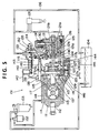
- a distributor type fuel injection pump 101 is mounted on a diesel engine, and supplies fuel, pressure fed by a single pumping element, by a rotating piston (plunger).
- a fuel tank 104 is connected via a fuel filter 102 and a fuel/water separator 103.
- an injection nozzle 105 for the diesel engine (not shown) is connected so that a predetermined amount of fuel at a predetermined pressure can be pressure fed with a predetermined timing and injected from the injection nozzle 105.
- the fuel injection pump 101 is also provided with an overflow passageway 106 for returning overflow fuel to the fuel tank 104.
- a shaft end portion of a drive shaft 112 is rotatably fitted into one side of the interior of a pump housing 111.
- a feed pump 113 (shown in a 90°-developed state in Fig. 5) is mounted on an intermediate part of the drive shaft 112.
- an intake passageway 114 extending from the fuel tank 104 is connected.
- the discharge side of the feed pump 113 is connected to a pump chamber 116 via a discharge passageway 115.
- a regulating valve 117 is inserted.
- the regulating valve 117 is connected to the intake passageway 114 via a return passageway 118.
- a cam plate 120 is connected via a coupling 119 so as to be integrally rotatable and relatively movable in the axial direction.
- a plunger 121 is secured to the cam plate 120.
- the drive shaft 112 passes through the pump housing 111, and a roller ring 122 is fixed so as to lie around the outer periphery of the coupling 119. Inside the roller ring 122, a plurality of rollers 123 are pivotably attached.
- a compression spring 124 is inserted between the pump housing 111 and the cam plate 120. By the urging force of this compression spring 124, the cam plate 120 and the plunger 121 are urged axially in one direction (leftward in Fig. 5).
- the cam surface of the cam plate 120 is contacted with, and pressed against, the respective rollers 123 of the roller ring 122.
- a fuel passageway 121a extending along the axial direction is formed, and an intake port 121b, a distribution port 121c and a spill port 121d are also formed.
- fuel in the pump chamber 116 may be sucked into the fuel passageway 121a through the intake port 121b.
- fuel sucked into the fuel passageway 121a may be discharged into a distribution passageway 125 through the distribution port 121c, or may be returned to the pump chamber 116 through the spill port 121d.
- the distribution passageway 125 is connected to the injection nozzle 105 via a delivery valve 126.
- a timer piston 127 (shown in a 90°-developed state in Fig. 5) is provided so as to be movable in a direction perpendicular to the drive shaft 112, and defines a low pressure chamber 127a and a high pressure chamber 127b.
- the low pressure chamber 127a communicates with the intake passageway 114 extending from the fuel tank 104 via a communication passage 146.
- the high pressure chamber 127b communicates with the pump chamber 116 via a communication passage 144 and an orifice 145.
- a slide pin 128 of the roller ring 122 engages the timer piston 127, and a compression spring 129 is mounted in the low pressure chamber 127a.
- the timer piston 127 Under the urging force of the compression spring 129, the timer piston 127 is urged axially in one direction (rightwards in Fig. 5). Thereby, the roller ring 122 is turned circumferentially to delay the injection timing by the plunger 121.
- An intake groove 130 of the pump housing 111 is provided with a fuel cut solenoid 131.
- a governor lever 132 On a side part of the pump housing 111, a governor lever 132 is mounted. To the governor lever 132, a tension lever 133 and a control lever 134 are pivotably attached. Between upper parts of the tension lever 133 and the control lever 134, a compression spring 135 is interposed. At the same time, a lower part of the control lever 134 engaged a spill ring 136 which is fitted over the plunger 121. To the drive shaft 112, a driving gear 137 is secured. The driving gear 137 meshes with a driven gear 139 of a governor shaft 138. Over the governor shaft 138, a governor sleeve 141 is fitted movably via a flyweight 140.
- an adjusting lever (accelerator lever) 142 is mounted on an upper part of the pump housing 111.
- a tension spring 143 is provided between the adjusting lever 142 and the tension lever 133. The urging force of the tension spring 143 brings the control lever 134 into contact with a front end part of the governor sleeve 141.
- the cam plate 120 When the cam plate 120 is rotated by the drive shaft 112, it reciprocates by the amount of cam lift on the respective rollers 123 attached to the roller ring 122. Thus, the plunger 121 connected to the cam plate 120 makes a rotary movement and a reciprocating movement.
- the intake of fuel is performed when the intake groove 130 and the intake port 121b align during the lowering of the plunger 121. Then, the plunger 121 rotates to bring the distribution port 121c and the distribution passageway 125 into alignment. At this time, fuel passes through the delivery valve 126, and is injected from the injection nozzle 105.
- the spill ring 136 is opened by the control lever 134, fuel in the plunger 121 is released to the pump chamber 116 through the spill port 121d, so that the fuel injection quantity is controlled. On this occasion, injection is completed.
- the fuel pressure of the pump chamber 116 acts on the nigh pressure chamber 127b via the communication passage 144 and the orifice 145, increasing the fuel pressure of the high pressure chamber 127b.
- the timer piston 127 is moved in a direction in which it compresses the spring 129.
- the timer piston 127 rotates the roller ring 122 to advance its angle, thereby controlling the injection timing.
- an ignition switch (not shown) is turned off, the electric current to the fuel cut solenoid 131 is interrupted to close the distribution passageway 125, cutting off the fuel.
- the fuel pressure inside the fuel tank 104 acts on the low pressure chamber 127a of the timer piston 127 through the intake passageway 114.
- the discharge fuel pressure by the feed pump 113 acts on the high pressure chamber 127b of the timer piston 127.
- the roller ring 122 is rotated so that its angle is advanced or retarded, whereby the injection timing is controlled.
- an electronically controlled fuel injection pump 101 has been proposed.
- a bypass passageway may be provided between the low pressure chamber 127a and the high pressure chamber 127b of the timer piston 127, and an electromagnetic valve may be inserted in the bypass passageway.
- the electromagnetic valve is actuated to duty drive the bypass passageway, thereby moving the timer piston 127. Consequently, the injection timing can be controlled elaborately.
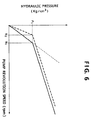
- the fuel pressure is controlled by the regulating valve 117. That is, as shown in Fig. 6, as the revolution speed of the feed pump 113 is increased, the fuel pressure of the pump chamber 116 is raised as indicated by a one-dot chain line. However, this fuel pressure is controlled as indicated by a solid line because of its control by the regulating valve 117. In this case, when the revolution speed of the feed pump 113 is N 1 , the fuel pressure is P 1 at which the injection timing can be controlled.
- the high pressure fuel in the pump chamber 116 is caused to overflow through the overflow passageway 106, whereby the fuel pressure of the pump chamber 116, i.e., the high pressure chamber 127b, is lowered.
- the urging pressure of the compression spring 129 provided in the low pressure chamber 127a of the timer piston 127 moves the timer piston 127 toward the high pressure chamber 127b.
- the bypass passageway may be closed by the electromagnetic valve that duty controls the timer piston 127.
- the high pressure fuel in the pump chamber 116 fails to be sufficiently released, with the result that the timer piston 127 may not return to the injection timing position at starting.
- the viscosity of fuel is so large that the resistance between the timer piston 127 and the corresponding outer wall portion may easily increase, and thus the timer piston 127 may not return to the injection timing position at starting. In this condition in which the timer piston 127 does not return to the injection timing position at starting, there has been the problem that when the ignition key switch is turned on, the startability of the engine declines.
- Japanese Laid-Open Utility Model Publication No. 35759/95 discloses an example of the foregoing distributor type fuel injection pump in which when the ignition switch is turned off, the internal pressure of fuel filling up the pump chamber is simultaneously lowered.
- This pump has a bypass passageway communicating from the discharge side to the intake side of the feed pump.
- the piston of the regulating valve of the fuel injection pump is pushed upwards to open the bypass passageway.
- the internal pressure of the fuel filling up the pump chamber is lowered for a fuel cutoff.
- the bypass passageway of the regulating valve can be opened to lower the fuel pressure inside the pump chamber.
- an orifice is interposed between the pump chamber and the nigh pressure chamber of the timer piston in order to prevent the decline in the control accuracy of the injection timing owing to the pulsation of the fuel pressure and its associated fine movement of the timer piston. Even when the fuel pressure inside the pump chamber has been reduced, therefore, it is difficult to release the fuel in the high pressure chamber of the timer piston to the pump chamber. This leads to insufficient reliability.
- the capacity of the pump chamber is large compared with the high pressure chamber of the timer piston.
- release of the fuel in the high pressure chamber of the timer piston into the pump chamber takes a long time.
- the regulating valve is continuously driven, thereby increasing the electric power consumption of the battery.
- the present invention aims to solve the above-described problems. Its object is to provide a fuel injection timing control device for a diesel engine, the control device having a simple and low-cost structure and reliably locating the timer piston at the injection timing position at starting, thereby improving startability.
- a fuel injection timing control device for a diesel engine comprises a feed pump for sucking up and feeding a constant amount of fuel from fuel stored in a fuel tank; a pump chamber for adjusting the fuel fed from the feed pump to a predetermined fuel pressure, a pump plunger for taking in a predetermined amount of fuel from the pump chamber and distributing and pressure feeding it to injection nozzles; a timer piston for controlling the fuel injection timing by the pump plunger, the timer piston having a low pressure chamber communicating with the upstream side of the feed pump and a high pressure chamber communicating with the pump chamber; a bypass passageway for establishing communication between the low pressure chamber and the high pressure chamber of the timer piston; a control valve for controlling the opening and closing state of the bypass passageway; and a fuel injection timing changing means which, when the engine is stopped, opens the bypass passageway by means of the control valve to allow the low pressure chamber and the high pressure chamber of the timer piston to communicate with each other for a predetermined time, thereby
- the timer piston controls the pump plunger-based fuel injection timing by relying on the pressure difference between the low pressure chamber communicating with the upstream side of the feed pump and the high pressure chamber communicating with the pump chamber.
- the bypass passageway is opened by the control valve to permit a predetermined time of communication between the low pressure chamber and the high pressure chamber of the timer piston.
- the fuel injection timing changing means shifts the timer piston to a maximum retard angle position.
- the timer piston is returned to the maximum retard angle position, whereby the fuel injection timing by the pump plunger is changed to the maximum retard angle position.
- the engine is started reliably.
- the pump chamber and the high pressure chamber communicate with each other via a restrictor.
- the presence of the restrictor gives the following advantage: Even in the fuel injection pump in which the fuel pressure of the high pressure chamber of the timer piston minimally lowers after a drop in the fuel pressure of the pump chamber, the timer piston is promptly returned to the injection timing position at starting. Thus, the electric power consumption of the battery is reduced, and the fuel injection timing by the pump plunger is changed to the injection timing position at starting. With the battery under protection, the engine is started reliably at the time of a next engine starting.
- a regulating valve for adjusting the fuel feed pressure of the feed pump is provided between the feed pump and the pump chamber, and an overflow valve is provided in a passageway for fuel return from the pump chamber to the fuel tank.
- the timer piston can be reliably moved to the injection timing position at starting, whereby the fuel injection timing by the pump plunger can be changed to the injection timing position at starting.
- a piston position detecting means is provided for detecting the position of the timer piston, and when the piston position detecting means detects that the timer piston position has become the injection timing position at starting, the shifting of the timer piston position by the fuel injection timing changing means is stopped.
- the fuel injection timing changing means can be controlled based on the communicating time or the actual timer piston position. This prevents the increase in the electric power consumption of the battery by excessive control of the injection timing changing means, as well as the insufficiency of the retard angle of the timer piston due to the insufficiency of the control of the injection timing changing means.
- the timer piston is returned to the injection timing position at starting, whereby the fuel injection timing by the pump plunger is changed to the injection timing position at starting.
- the engine is started reliably at the time of a next engine starting.
- a fuel injection timing control device for a diesel engine comprises a feed pump for sucking up and feeding a constant amount of fuel from fuel stored in a fuel tank; a pump chamber for adjusting the fuel fed from the feed pump to a predetermined fuel pressure; a pump plunger for taking in a predetermined amount of fuel from the pump chamber and distributing and pressure feeding it to injection nozzles; a timer piston for controlling the fuel injection timing by the pump plunger, the timer piston having a low pressure chamber communicating with the upstream side of the feed pump and a high pressure chamber communicating with the pump chamber; a bypass passageway for establishing communication between the low pressure chamber and the high pressure chamber of the timer piston; a control valve for controlling the opening and closing state of the bypass passageway; piston position detecting means for detecting the position of the timer piston; and fuel injection timing changing means which, when the engine is stopped, opens the bypass passageway by means of the control valve to allow the low pressure chamber and the high pressure chamber of the timer piston
- the injection timing changing means can be controlled based on the actual timer piston position. This prevents the increase in the electric power consumption of the battery by excessive control of the injection timing changing means, as well as the insufficiency of the retard angle of the timer piston due to the insufficiency of the control of the injection timing changing means.
- the timer piston is returned to the maximum retard angle position, whereby the fuel injection timing by the pump plunger is changed to the maximum retard angle position.
- a distributor type fuel injection pump 11 is mounted on a diesel engine 12.
- a fuel tank 13 is connected, so that fuel stored in the fuel tank 13 can be sucked up in a predetermined amount.
- injection nozzles 14 of the diesel engine 12 are connected so that a predetermined amount of fuel at a predetermined pressure can be pressure fed with a predetermined timing and injected from each injection nozzle 14.
- an engine control unit 15 is connected to the diesel engine 12. Based on the engine run state of the engine control unit 15 and the operation of an ignition switch 16, an injection timing changing means 17 is controlled, whereby the fuel injection timing by the fuel injection pump 11 can be changed.
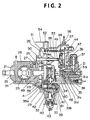
- the fuel injection pump 11 is described in detail here.
- a shaft end portion of a drive shaft 22 is rotatably fitted into one side of the interior of a pump housing 21.
- a feed pump 23 (shown in a 90°-developed state in Fig. 2) is mounted on an intermediate part of the drive shaft 22 .
- an intake passageway 24 extending from the fuel tank 13 is connected to the feed pump 23 .
- the discharge side of the feed pump 23 is connected to a pump chamber 26 via a discharge passageway 25.
- a regulating valve 27 is disposed at a midway part of the discharge passageway 25, a regulating valve 27 is disposed.
- the ragulating valve 27 is connected to the intake passageway 24 via a return passageway 28.
- a cam plate 30 is connected via a coupling 29 so as to be integrally rotatable and relatively movable in the axial direction.
- a plunger 31 is secured to the cam plate 30, and a roller ring 32 is fixed so as to lie around the outer periphery of the coupling 29. Inside the roller ring 32, a plurality of rollers 33 are pivotably mounted.
- a compression spring 34 is interposed between the pump housing 21 and the cam plate 30, a compression spring 34 is interposed. By the urging force of this compression spring 34, the cam plate 30 and the plunger 31 are urged axially in one direction (leftward in Fig. 2). Thus, the cam surface of the cam plate 30 is pressed against the respective rollers 33 of the roller ring 32.
- a fuel passageway 31a extending along the axial direction is formed, and an intake port 31b, a distribution port 31c and a spill port 31d are also formed.
- fuel in the pump chamber 26 may be sucked into the fuel passageway 31a through the intake port 31b.
- fuel sucked into the fuel passageway 31a may be discharged into a distribution passageway 35 through the distribution port 31c, or may be returned to the pump chamber 26 through the spill port 31d.
- An intake groove 36 of the pump housing 31 is provided with a fuel cut solenoid 37, and the distribution passageway 35 is connected to the injection nozzles 14 via a delivery valve 38.
- a timer piston 39 (shown in a 90°-developed state in Fig. 2) is provided so as to be movable in a direction perpendicular to the drive shaft 22, and defines a low pressure chamber 39a and a high pressure chamber 39b.
- the low pressure chamber 39a communicates with the intake passageway 24 extending from the fuel tank 13 via a communication passage 59.
- the high pressure chamber 39b communicates with the pump chamber 26 via a communication passage 60 and an orifice 61.
- a slide pin 40 of the roller ring 32 engages the timer piston 39, and a compression spring 41 is mounted in the low pressure chamber 39a. Under the urging force of the compression spring 41, the timer piston 39 is urged axially in one direction (rightwards in Fig. 2). Thereby, the roller ring 32 is turned circumferentially to delay the injection timing by the plunger 31.
- the timer piston 39 is provided with a bypass passageway 42 for communication between the low pressure chamber 39a and the high pressure chamber 39b, and is also provided with a control valve 43 for opening and closing the bypass passageway 42.
- the aforementioned injection timing changing means 17 controls the electricity turn-on time of the control valve 43 in accordance with the run state of the engine to control the communication state of the bypass passageway 42. As a result, communication between the low pressure chamber 39a and the high pressure chamber 39b is controlled, whereupon the fuel injection timing by the fuel injection pump 11 can be controlled.
- the injection timing changing means 17 also opens the bypass passageway 42 by the control valve 43 when the engine is stopped. Consequently, the low pressure chamber 39a and the high pressure chamber 39b of the timer piston 39 are made to communicate for a predetermined time.
- the timer piston 39 can be brought to the injection timing position at starting (with a diesel engine, this position is often set to be nearly the maximum retard angle position for improved startability). This means that the fuel injection timing by the pump plunger 31 can be changed to the injection timing position at starting.
- a governor lever 44 On a side part of the pump housing 21, a governor lever 44 is mounted. To the governor lever 44, a tension lever 45 and a control lever 46 are pivotably attached. Between upper parts of the tension lever 45 and the control lever 46, a compression spring 47 is interposed. At the same time, a lower part of the control lever 46 engages a spill ring 48 which is fitted over the plunger 31. To the drive shaft 22, a driving gear 49 is secured. The driving gear 49 meshes with a driven gear 51 of a governor shaft 50. Over the governor shaft 50, a governor sleeve 53 is fitted movably via a flyweight 52. On an upper part of the pump housing 21, an adjusting lever (accelerator lever) 54 is mounted. Between the adjusting lever 54 and the tension lever 45, a tension spring 55 is provided. The urging force of the tension spring 55 brings the control lever 46 into contact with a front end part of the governor sleeve 53.
- the pump housing 21 of the fuel injection pump 11 is also provided with an overflow passageway 56 for returning overflow fuel from the pump chamber 26 to the fuel tank 13.
- an overflow valve 57 is provided at the junction of the overflow passageway 56 and the pump chamber 26, an overflow valve 57 is provided.
- the diesel engine 12 is driven. Its half rotation results in the driving rotation of the drive shaft 22, accompanied by the rotational driving of the feed pump 23.
- the feed pump 23 is rotationally driven, fuel is fed to the pump chamber 26 via the discharge passageway 25, with the fuel pressure being controlled by the regulating valve 27.
- the plunger 31 is rotated by the cam plate 30 connected to the drive shaft 22 by the coupling 29.
- the cam plate 30 has the same number of face cams as the number of cylinders of the engine 12.
- the cam plate 30 is rotated by the drive shaft 22, only the cam lift reciprocates on the respective rollers 33 attached to the roller ring 32.
- the plunger 31 connected to the cam plate 30 makes a rotary movement and a reciprocating movement.
- the intake groove 36 and the intake port 31b align, so that fuel in the pump chamber 26 is sucked into the fuel passageway 31a through the intake groove 36 and the intake port 31b.
- the intake port 31b closes, and the distribution port 31c and the distribution passageway 35 come into alignment.
- the fuel in the plunger 31 increases in pressure.
- the pressurized fuel is passed through the delivery valve 38, and fed to the injection nozzles 14, which begin injection.
- the spill port 31d goes outside the range of its interference with the spill ring 48.
- the spill port 31d opens, whereupon the fuel in the plunger 31 is released to the pump chamber 26 through the spill port 31d. At this time, injection ends.
- the spill ring 48 When the adjusting lever 54 is turned, the spill ring 48 is moved by the action of the governor lever 44, tension lever 45 and control lever 46, so that the effective stroke of the plunger 31 changes. That is, when the spill ring 48 is moved leftward in Fig. 2, the opening of the spill port 31d is expedited, so that the amount of fuel pressure fed becomes small. When the spill ring 48 is moved rightward in Fig. 2, on the other hand, the opening of the spill port 31d is delayed, so that the amount of fuel pressure fed becomes large. This way, the amount of fuel injection can be controlled.
- the compression spring 41 is mounted in the low pressure chamber 39a of the timer piston 39.
- the urging force of the compression spring 41 urges the timer piston 39 in one direction, whereby the roller ring 32 is turned circumferentially to delay the injection timing by the plunger 31.
- the fuel pressure of the pump chamber 26 acts on the high pressure chamber 39b of the timer piston 39 via the communication passage 60 and orifice 61.
- the timer piston 39 moves against the urging force of the compression spring 41.
- the timer piston 39 rotates the roller ring 32 to advance its angle, thereby making it possible to control the injection timing.
- the control valve 43 opens the bypass passageway 42, causing the low pressure chamber 39a and the high pressure chamber 39b of the timer piston 39 to communicate for a predetermined period of time.
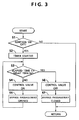
- the timer piston 39 can be returned to the injection timing position at starting. That is, as shown in Fig. 3, it is determined at step S1 whether the ignition switch was turned off at this cycle. If the ignition switch is ON, the initial state is resumed. If the ignition switch is OFF at the step S1, the procedure goes to step S2 to start the timer. At step S3, it is determined whether the elapsed time t since the start of the timer is more than a preset delay time t 0 . At step S4, the control valve 43 is turned on.
- step S5 the bypass passageway 42 is opened, whereafter the procedure returns to step S3.
- steps S3, S4 and S5 the indicated processings are repeated until the elapsed time t exceeds the delay time t 0 .
- the control valve 43 is turned off.
- step S7 the bypass passageway 42 is closed.
- the control valve 43 opens the bypass passageway 42, causing the low pressure chamber 39a and the high pressure chamber 39b of the timer piston 39 to communicate for a predetermined period of time.
- the differential pressure existing between the low pressure chamber 39a and the high pressure chamber 39b (pump chamber 26) rapidly vanishes.
- the timer piston 39 moves to the ignition timing position at starting, thereby permitting the fuel ignition timing to be changed to the ignition timing position at starting by the plunger 31 via the roller ring 32.
- load on the battery can be decreased, and battery deterioration can be diminished.
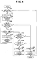
- Fig. 4 shows a flow chart for control by a fuel injection timing control device concerned with another embodiment.
- step S11 it is determined at step S11 whether the ignition switch was turned off at this cycle. If the ignition switch is ON, the initial state is resumed. If the ignition switch is OFF at the step S11, the procedure goes to step S12 to start the timer.
- step S13 the current position P of the timer piston 39 is detected by a position sensor PS (piston position detecting means; see Fig. 1) .
- step S14 it is determined whether the current position P of the timer piston 39 is smaller than the starting position Ps (retarded in angle). If the current position P of the timer piston 39 is smaller than the starting position Ps, it is determined that the timer piston 39 has been retarded in angle to the injection timing position at starting. Thus, the procedure goes to step S22. At the step S22, the control valve 43 is turned off. At step S23, the bypass passageway 42 is closed.
- step S14 If, at the step S14, the current position P of the timer piston 39 is larger than the starting position Ps, it is determined that the timer piston 39 has not been retarded in angle to the injection timing position at starting.
- step S15 it is determined whether the elapsed time t since the start of the timer is more than a preset delay time t 0 .
- step S16 the control valve 43 is turned on.
- step S17 the bypass passageway 42 is opened, whereafter the procedure returns to step S13.
- the indicated processings are repeated until the timer piston position P exceeds the starting position Ps, or the elapsed time t exceeds the delay time t 0 .
- the procedure goes to step S18.
- step S18 it is determined again whether the current position P of the timer piston 39 is smaller than the starting position Ps. If the current position P of the timer piston 39 is smaller than the starting position Ps, it is determined that the timer piston 39 has been retarded in angle to the injection timing position at starting. Then, as steps S22 and S23, the control valve 43 is turned off, and the bypass passageway 42 is closed, respectively. If, at step S18, the current position P of the timer piston 39 is larger than the starting position Ps, it is determined that the timer piston 39 has not been retarded in angle to the injection timing position at starting.
- step S19 it is determined whether the elapsed time t since the start of the timer is more than a second delay time t 2 which has been set to be longer than the delay time t 0 . If the elapsed time t is less than the second delay time t 2 , the control valve 43 is turned on at step S20. At step S21, the bypass passageway 42 is opened. Then, the step S18 is resumed. At these steps S18, S19, S20, and S21, the indicated processings are repeated until the timer piston position P exceeds the starting position Ps, or the elapsed time t exceeds the second delay time t 2 .
- the viscosity of fuel is so large that the resistance between the timer piston 39 and the corresponding outer wall portion may increase, making it difficult for the timer piston 39 to return to the Injection timing position at starting or the maximum retard angle position.
- the timer piston 39 can reliably be returned to the injection timing position at starting or the maximum retard angle position by controlling the control valve 43 based on the timer piston position. Even if the drag between the timer piston 39 and the corresponding outer wall portion results in the failure of the timer piston 39 to return to the injection timing position at starting or the maximum retard angle position, the increase in the electric power consumption of the battery can be prevented by controlling the control valve 43 based on the timer piston position.
- the bypass passageway is opened upon stoppage of the engine to permit a predetermined time of communication between the low pressure chamber and the high pressure chamber.
- the fuel pressure of the high pressure chamber is released via the low pressure chamber, whereby the timer piston is moved to the injection timing position at starting.
- the fuel injection timing by the pump plunger can be changed to the injection timing position at starting.
- the timer piston is returned to the maximum retard angle position, whereby the fuel injection timing by the pump plunger is changed to the maximum retard angle position.
- the engine can be started reliably.
- the fuel injection timing control device for a diesel engine as the third aspect of the invention, there is a restrictor between the pump chamber and the high pressure chamber, thus presenting the following advantages: Even in the fuel injection pump in which the fuel pressure of the high pressure chamber of the timer piston minimally lowers after a drop in the fuel pressure of the pump chamber, the timer piston is promptly returned to the injection timing position at starting. Thus, the electric power consumption of the battery is reduced, and the fuel injection timing by the pump plunger is changed to the injection timing position at starting. With the battery under protection, the engine can be started reliably at the time of a next engine starting.
- the fuel injection timing control device for a diesel engine as the fourth aspect of the invention, the following advantages are obtained: Even when the regulating valve and the overflow valve are closed upon stoppage of the engine, the timer piston can be reliably moved to the injection timing position at starting, whereby the fuel injection timing by the pump plunger can be changed to the injection timing position at starting.
- the fuel injection timing changing means can be controlled based on the actual timer piston position. This prevents the increase in the electric power consumption of the battery by excessive control of the injection timing changing means, as well as the insufficiency of the retard angle of the timer piston due to the insufficiency of the control of the injection timing changing means.
- the timer piston is returned to the injection timing position at starting, whereby the fuel injection timing by the pump plunger is changed to the injection timing position at starting.
- the engine can be started reliably at the time of a next engine starting.
- the injection timing changing means can be controlled based on the actual timer piston position. This prevents the increase in the electric power consumption of the battery by excessive control of the injection timing changing means, as well as the insufficiency of the retard angle of the timer piston due to the insufficiency of the control of the injection timing changing means.
- the timer piston is returned to the maximum retard angle position, whereby the fuel injection timing by the pump plunger is changed to the maximum retard angle position.
Landscapes
- Engineering & Computer Science (AREA)
- Chemical & Material Sciences (AREA)
- Combustion & Propulsion (AREA)
- Mechanical Engineering (AREA)
- General Engineering & Computer Science (AREA)
- High-Pressure Fuel Injection Pump Control (AREA)
- Fuel-Injection Apparatus (AREA)
- Output Control And Ontrol Of Special Type Engine (AREA)
- Electrical Control Of Air Or Fuel Supplied To Internal-Combustion Engine (AREA)
Applications Claiming Priority (6)
| Application Number | Priority Date | Filing Date | Title |
|---|---|---|---|
| JP22627696 | 1996-08-28 | ||
| JP226276/96 | 1996-08-28 | ||
| JP22627696 | 1996-08-28 | ||
| JP20270997A JP3759291B2 (ja) | 1996-08-28 | 1997-07-29 | ディーゼルエンジンの燃料噴射時期制御装置 |
| JP202709/97 | 1997-07-29 | ||
| JP20270997 | 1997-07-29 |
Publications (3)
| Publication Number | Publication Date |
|---|---|
| EP0831228A2 true EP0831228A2 (de) | 1998-03-25 |
| EP0831228A3 EP0831228A3 (de) | 1999-10-27 |
| EP0831228B1 EP0831228B1 (de) | 2003-01-29 |
Family
ID=26513539
Family Applications (1)
| Application Number | Title | Priority Date | Filing Date |
|---|---|---|---|
| EP97114858A Expired - Lifetime EP0831228B1 (de) | 1996-08-28 | 1997-08-27 | Steuervorrichtung für den Kraftstoffeinspritzpunkt eines Dieselmotors |
Country Status (5)
| Country | Link |
|---|---|
| EP (1) | EP0831228B1 (de) |
| JP (1) | JP3759291B2 (de) |
| KR (1) | KR100303119B1 (de) |
| DE (1) | DE69718732T2 (de) |
| MY (1) | MY121284A (de) |
Cited By (2)
| Publication number | Priority date | Publication date | Assignee | Title |
|---|---|---|---|---|
| US6140638A (en) * | 1997-06-04 | 2000-10-31 | Mds Inc. | Bandpass reactive collision cell |
| US9343779B2 (en) | 2012-11-23 | 2016-05-17 | Lg Chem, Ltd. | Method of preparing electrode assembly and electrode assembly prepared using the method |
Families Citing this family (1)
| Publication number | Priority date | Publication date | Assignee | Title |
|---|---|---|---|---|
| KR100371445B1 (ko) * | 2000-11-13 | 2003-02-07 | 주식회사 두원정공 | 디젤엔진용 전자제어 연료 분사장치에 있어 분사시기를타이밍 제어하기 위한 연산 방법 및 이를 이용한분사시기의 타이밍 제어방법 |
Family Cites Families (5)
| Publication number | Priority date | Publication date | Assignee | Title |
|---|---|---|---|---|
| JPS58143133A (ja) * | 1982-02-22 | 1983-08-25 | Mitsuwa Seiki Co Ltd | 燃料噴射時期制御装置 |
| JPS6090930A (ja) * | 1983-10-25 | 1985-05-22 | Yanmar Diesel Engine Co Ltd | 内燃機関用タイマ−装置 |
| JPS63138128A (ja) * | 1986-11-28 | 1988-06-10 | Mazda Motor Corp | デイ−ゼルエンジンの燃料噴射時期制御装置 |
| JPH01155055A (ja) * | 1987-12-11 | 1989-06-16 | Kubota Ltd | ディーゼルエンジンのシーケンス式燃料噴射時期制御装置 |
| JP3215962B2 (ja) * | 1993-12-09 | 2001-10-09 | 株式会社ボッシュオートモーティブシステム | 電子式燃料噴射装置の噴射時期調整装置 |
-
1997
- 1997-07-29 JP JP20270997A patent/JP3759291B2/ja not_active Expired - Fee Related
- 1997-08-27 DE DE69718732T patent/DE69718732T2/de not_active Expired - Fee Related
- 1997-08-27 EP EP97114858A patent/EP0831228B1/de not_active Expired - Lifetime
- 1997-08-28 MY MYPI97003987A patent/MY121284A/en unknown
- 1997-08-28 KR KR1019970042086A patent/KR100303119B1/ko not_active Expired - Fee Related
Cited By (2)
| Publication number | Priority date | Publication date | Assignee | Title |
|---|---|---|---|---|
| US6140638A (en) * | 1997-06-04 | 2000-10-31 | Mds Inc. | Bandpass reactive collision cell |
| US9343779B2 (en) | 2012-11-23 | 2016-05-17 | Lg Chem, Ltd. | Method of preparing electrode assembly and electrode assembly prepared using the method |
Also Published As
| Publication number | Publication date |
|---|---|
| JPH10121990A (ja) | 1998-05-12 |
| MY121284A (en) | 2006-01-28 |
| KR100303119B1 (ko) | 2001-11-30 |
| EP0831228A3 (de) | 1999-10-27 |
| JP3759291B2 (ja) | 2006-03-22 |
| DE69718732T2 (de) | 2003-12-24 |
| EP0831228B1 (de) | 2003-01-29 |
| KR19980019112A (ko) | 1998-06-05 |
| DE69718732D1 (de) | 2003-03-06 |
Similar Documents
| Publication | Publication Date | Title |
|---|---|---|
| JP3794205B2 (ja) | コモンレール式燃料噴射装置 | |
| EP2010780B1 (de) | Kraftstoffversorgungssystem für verbrennungsmotor | |
| EP1219827B1 (de) | Kraftstoffeinspritzsystem für Verbrennungsmotoren, mit einer Hochdruckpumpe angetrieben über einen geformten Nocken | |
| US7801672B2 (en) | After-stop fuel pressure control device of direct injection engine | |
| JPH04272471A (ja) | ディーゼル機関の蓄圧式燃料噴射装置 | |
| EP0524132B1 (de) | Brennstoffsystem für eine Rotationsverteilerbrennstoffeinspritzpumpe | |
| EP0831228B1 (de) | Steuervorrichtung für den Kraftstoffeinspritzpunkt eines Dieselmotors | |
| JP3683047B2 (ja) | 過給機付ディーゼル機関の加速制御装置 | |
| JP3360336B2 (ja) | 内燃機関の燃料噴射装置 | |
| US4674461A (en) | Unit injector for internal combustion engines | |
| JP3070961B2 (ja) | 噴射ポンプの噴射残量を減少させる方法 | |
| US4932385A (en) | Fuel injection pump for internal combustion engines | |
| US4563992A (en) | Diesel fuel injection pump with electronically controlled fuel spilling and cutoff and recirculation venting of spilt fuel | |
| JPS6255454A (ja) | 燃料噴射ポンプ | |
| JPS61212661A (ja) | 分配型燃料噴射ポンプ | |
| JP2512960B2 (ja) | 高圧燃料ポンプ制御装置 | |
| JPH0341089Y2 (de) | ||
| JPH02102361A (ja) | ディーゼル機関の燃料噴射制御装置 | |
| EP0812982B1 (de) | Kraftstoffeinspritzungssteuergerät für einen elektronisch geregelten Dieselmotor | |
| JP2512893B2 (ja) | 燃料噴射装置 | |
| JP3906775B2 (ja) | 分配型燃料噴射ポンプ | |
| EP0884467B1 (de) | Kraftstoffeinspritzanlage eines Dieselmotors | |
| JPS62291463A (ja) | 燃料噴射装置 | |
| JPS5833237Y2 (ja) | 分配型燃料噴射ポンプの噴射時期調整装置 | |
| JPS5833238Y2 (ja) | 分配型燃料噴射ポンプの噴射時期調整装置 |
Legal Events
| Date | Code | Title | Description |
|---|---|---|---|
| PUAI | Public reference made under article 153(3) epc to a published international application that has entered the european phase |
Free format text: ORIGINAL CODE: 0009012 |
|
| AK | Designated contracting states |
Kind code of ref document: A2 Designated state(s): DE FR |
|
| AX | Request for extension of the european patent |
Free format text: AL;LT;LV;RO;SI |
|
| PUAL | Search report despatched |
Free format text: ORIGINAL CODE: 0009013 |
|
| AK | Designated contracting states |
Kind code of ref document: A3 Designated state(s): AT BE CH DE DK ES FI FR GB GR IE IT LI LU MC NL PT SE |
|
| AX | Request for extension of the european patent |
Free format text: AL;LT;LV;RO;SI |
|
| 17P | Request for examination filed |
Effective date: 19991118 |
|
| AKX | Designation fees paid |
Free format text: DE FR |
|
| GRAG | Despatch of communication of intention to grant |
Free format text: ORIGINAL CODE: EPIDOS AGRA |
|
| 17Q | First examination report despatched |
Effective date: 20020228 |
|
| GRAG | Despatch of communication of intention to grant |
Free format text: ORIGINAL CODE: EPIDOS AGRA |
|
| GRAG | Despatch of communication of intention to grant |
Free format text: ORIGINAL CODE: EPIDOS AGRA |
|
| GRAH | Despatch of communication of intention to grant a patent |
Free format text: ORIGINAL CODE: EPIDOS IGRA |
|
| GRAH | Despatch of communication of intention to grant a patent |
Free format text: ORIGINAL CODE: EPIDOS IGRA |
|
| GRAA | (expected) grant |
Free format text: ORIGINAL CODE: 0009210 |
|
| RIN1 | Information on inventor provided before grant (corrected) |
Inventor name: YAMANE, SHINJI Inventor name: HASHIMOTO, MITSUO Inventor name: NOTANI, KAZUHIRO |
|
| AK | Designated contracting states |
Designated state(s): DE FR |
|
| REF | Corresponds to: |
Ref document number: 69718732 Country of ref document: DE Date of ref document: 20030306 Kind code of ref document: P |
|
| ET | Fr: translation filed | ||
| PLBE | No opposition filed within time limit |
Free format text: ORIGINAL CODE: 0009261 |
|
| STAA | Information on the status of an ep patent application or granted ep patent |
Free format text: STATUS: NO OPPOSITION FILED WITHIN TIME LIMIT |
|
| 26N | No opposition filed |
Effective date: 20031030 |
|
| REG | Reference to a national code |
Ref country code: FR Ref legal event code: CA |
|
| PGFP | Annual fee paid to national office [announced via postgrant information from national office to epo] |
Ref country code: DE Payment date: 20070823 Year of fee payment: 11 |
|
| PGFP | Annual fee paid to national office [announced via postgrant information from national office to epo] |
Ref country code: FR Payment date: 20070808 Year of fee payment: 11 |
|
| REG | Reference to a national code |
Ref country code: FR Ref legal event code: ST Effective date: 20090430 |
|
| PG25 | Lapsed in a contracting state [announced via postgrant information from national office to epo] |
Ref country code: FR Free format text: LAPSE BECAUSE OF NON-PAYMENT OF DUE FEES Effective date: 20080901 Ref country code: DE Free format text: LAPSE BECAUSE OF NON-PAYMENT OF DUE FEES Effective date: 20090303 |