EP0831202A2 - Verfahren und Vorrichtung zum Auftragen eines plastischen Abstandhalters für Isolierglasscheiben auf eine Glastafel - Google Patents
Verfahren und Vorrichtung zum Auftragen eines plastischen Abstandhalters für Isolierglasscheiben auf eine Glastafel Download PDFInfo
- Publication number
- EP0831202A2 EP0831202A2 EP97114171A EP97114171A EP0831202A2 EP 0831202 A2 EP0831202 A2 EP 0831202A2 EP 97114171 A EP97114171 A EP 97114171A EP 97114171 A EP97114171 A EP 97114171A EP 0831202 A2 EP0831202 A2 EP 0831202A2
- Authority
- EP
- European Patent Office
- Prior art keywords
- nozzle
- glass sheet
- horizontal conveyor
- conveyor
- glass
- Prior art date
- Legal status (The legal status is an assumption and is not a legal conclusion. Google has not performed a legal analysis and makes no representation as to the accuracy of the status listed.)
- Withdrawn
Links
- 239000011521 glass Substances 0.000 title claims abstract description 47
- 229920003023 plastic Polymers 0.000 title claims abstract description 18
- 239000004033 plastic Substances 0.000 title claims abstract description 18
- 125000006850 spacer group Chemical group 0.000 title claims description 6
- 238000000034 method Methods 0.000 title claims description 5
- 239000000463 material Substances 0.000 claims abstract description 14
- 238000003860 storage Methods 0.000 claims description 8
- 238000012432 intermediate storage Methods 0.000 description 2
- 238000004519 manufacturing process Methods 0.000 description 2
- 206010041953 Staring Diseases 0.000 description 1
- 229920005549 butyl rubber Polymers 0.000 description 1
- 238000011161 development Methods 0.000 description 1
- 230000018109 developmental process Effects 0.000 description 1
- 238000010438 heat treatment Methods 0.000 description 1
- 230000007257 malfunction Effects 0.000 description 1
- 230000001360 synchronised effect Effects 0.000 description 1
Images
Classifications
-
- E—FIXED CONSTRUCTIONS
- E06—DOORS, WINDOWS, SHUTTERS, OR ROLLER BLINDS IN GENERAL; LADDERS
- E06B—FIXED OR MOVABLE CLOSURES FOR OPENINGS IN BUILDINGS, VEHICLES, FENCES OR LIKE ENCLOSURES IN GENERAL, e.g. DOORS, WINDOWS, BLINDS, GATES
- E06B3/00—Window sashes, door leaves, or like elements for closing wall or like openings; Layout of fixed or moving closures, e.g. windows in wall or like openings; Features of rigidly-mounted outer frames relating to the mounting of wing frames
- E06B3/66—Units comprising two or more parallel glass or like panes permanently secured together
- E06B3/673—Assembling the units
- E06B3/67326—Assembling spacer elements with the panes
- E06B3/6733—Assembling spacer elements with the panes by applying, e.g. extruding, a ribbon of hardenable material on or between the panes
-
- E—FIXED CONSTRUCTIONS
- E06—DOORS, WINDOWS, SHUTTERS, OR ROLLER BLINDS IN GENERAL; LADDERS
- E06B—FIXED OR MOVABLE CLOSURES FOR OPENINGS IN BUILDINGS, VEHICLES, FENCES OR LIKE ENCLOSURES IN GENERAL, e.g. DOORS, WINDOWS, BLINDS, GATES
- E06B3/00—Window sashes, door leaves, or like elements for closing wall or like openings; Layout of fixed or moving closures, e.g. windows in wall or like openings; Features of rigidly-mounted outer frames relating to the mounting of wing frames
- E06B3/66—Units comprising two or more parallel glass or like panes permanently secured together
- E06B3/673—Assembling the units
- E06B3/67365—Transporting or handling panes, spacer frames or units during assembly
Definitions
- the invention relates to a method with the preamble of the claim 1 specified features and of a device with the in The preamble of claim 2 features specified.
- a process and such a device are disclosed in EP 0 176 388 A1.
- the well-known Device has a stand-up conveyor as a horizontal conveyor for glass panels Form a horizontal line of synchronously driven rollers and above as a support device, a support wall, in particular an air cushion wall, which is tilted a little backwards so that the glass panels are on the stand-up conveyor stand, lean against the retaining wall without falling over.
- a suction conveyor belt which is synchronous with the stand-up conveyor is drivable, sucks the glass panels near their lower edge and for one slip-free movement of the glass panels ensures.
- the horizontal conveyor is stationary arranged; it rests on a fixed frame.
- a column is arranged at a distance from the horizontal conveyor, which is inclined in the same way as the retaining wall.
- the sled has a buffer for plastic material, a nozzle, and between the two a dosing pump.
- the Nozzle is arranged around the support wall or in front of the support wall Glass panel vertical axis rotatable.
- the intermediate store is heated Pipeline in which there are heated swivel joints with a Drum pump connected, which is located on a barrel, in which a supply is present on the plastic material.
- the plastic material is from the drum pump is conveyed into the intermediate storage, from there through the metering pump withdrawn and metered fed to the nozzle, which they as a strand on a Applies glass panel, which stands on the horizontal conveyor.
- the nozzle can on the vertical glass edges be moved along; by moving the glass sheet horizontally
- the glass panel can be used to drive the stand-up conveyor and the suction conveyor belt their two horizontal edges along the nozzle.
- a plastic strand can run continuously along all four edges of one Glass sheet can be applied, with the nozzle in the area of the corners of the glass sheet makes a 90 ° turn.
- the present invention has for its object to show a way like the expenditure on equipment for the application of a plastic spacer can be reduced to a glass panel.
- the invention makes a departure from the prior art in that the nozzle apart from rotary movements around its axis and apart from if necessary. necessary short infeed movements of the nozzle against the glass sheet stationary is held and instead the glass sheet is moved two-dimensionally around it with their edges moving continuously along the nozzle, taking in the area the corners of the glass sheets the nozzle rotates or in the case of model discs along an arcuate edge according to the course the tangent is gradually rotated.
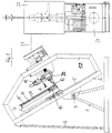
- the device carries on a base 1 a frame 2, which around a horizontal axis 3 pivotally mounted, but by struts 4, which the Connect the frame 2 to the base frame 1 in a certain angular position is fixed.
- the struts 4 can contain a spindle, not shown, around the Adjust the inclination of the frame 2 when setting up the device.
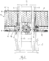
- the frame carries two mutually parallel, extending from bottom to top Guide rods (5 and 6) on which a horizontal conveyor 7 on and is guided from sliding.
- the horizontal conveyor 7 comprises a rectangular frame 8, which is below a stand-up conveyor 9, which consists of endless conveyor belts 10 and 11th and there is a horizontal row of rollers 12 arranged between them, which are driven synchronously.
- a Support device 13 is provided, consisting of a field of free-running Support rollers 14 which are rotatable about axes 15 which are in the frame 8 of extend from bottom to top. Instead of such a field of support rollers 14 an air cushion wall could also be provided.
- a suction conveyor belt 16 Between the field of Support rollers and the erection conveyor 9 is still a suction conveyor belt 16, which can be driven synchronously with the stand-up conveyor 9.
- Such a suction conveyor belt is known from DE-35 29 892 A1.
- the frame 2 is spanned by a bridge 17, on which a nozzle 18 together is attached with their ancillary units, including a Buffer 19 and a gear pump 20 belong.
- a Buffer 19 can be a piston-cylinder unit, the pistons for Generation of a selectable admission pressure for the gear pump is.
- a storage container 21 which holds the plastic material, contains in particular a butyl rubber, which as a strand on a Glass board should be applied.
- a pump unit is located above the reservoir 21 22 arranged, of which a rigid pipe 23 on short Path to the buffer 19 leads.
- the entire device is integrated into an insulating glass production line, which has a horizontal conveyor, the inclination of which corresponds to the inclination of the horizontal conveyor 7 matches, but is arranged stationary.
- the horizontal conveyor 7 Around enter a glass sheet in the production line into the device according to the invention to be able to leave, the horizontal conveyor 7 to the fixed level of adjacent horizontal conveyor lowered in the line. Then one can Glass panel 24 enter the horizontal conveyor 7, on which they in a predetermined Position is stopped, in which the stationary nozzle the edge of the Glass panel 24 is reproducibly opposite.
- the nozzle 18 is now in the direction of Rotation axis, which runs perpendicular to the glass sheet 24, on a short way against the glass sheet 24 is delivered and then begins along the edge of the glass sheet 24 extrude a strand, the strand being along the horizontal edges the glass sheet 24 is applied, in which the glass sheet on the horizontal conveyor 7 by driving the stand-up conveyor 9 in one direction or the other is moved, whereas along the edges running from top to bottom the strand is applied by the frame 8 together with the stand-up conveyor 9 and the field of support rollers 14 along the guide rods 5 upwards or is moved down, the nozzle 18 is rotated whenever a Corner of the glass sheet has reached the nozzle 18.
Landscapes
- Engineering & Computer Science (AREA)
- Civil Engineering (AREA)
- Structural Engineering (AREA)
- Joining Of Glass To Other Materials (AREA)
- Coating Apparatus (AREA)
Abstract
Description
- Die Faßpumpe kann kleiner, leichter, schwächer und preiswerter sein.
- Der Aufwand für die Leitungsführung zum Zwischenspeicher ist drastisch reduziert. Insbesondere werden keine teueren Drehgelenke benötigt.
- Wegen der geringen Drücke können anstelle von starren Rohrleitungen sogar preiswerte Druckschläuche verwendet werden.
- Es entfällt die Säule mit den Antriebs- und Führungseinrichtungen für die Düse und deren Hilfsaggregate (Dosierpumpe, Zwischenspeicher, Ventile, Stellgeräte, Heizeinrichtungen, Drehantriebe).
- Statt dessen muß lediglich eine Hebeeinrichtung für den Waagerechtförderer vorgesehen sein.
- Zumindest für kleinere Glastafelformate die in der Praxis am gebräuchlichsten sind, kommt man so zu einer Vorrichtung zum Auftragen eines plastischen Abstandhalters, deren Kosten gegenüber dem Stand der Technik drastisch sinken.
- Die Auf- und Abbewegung des Waagerechfförderers ist einfacher zu realisieren als die Auf- und Abbewegung der Düse mit ihren Nebenaggregaten beim Stand der Technik. Es hat sich gezeigt, daß man bei Glastafelformaten bis 1 m x 2 m nicht mehr als 300 kg Masse des Waagerechtförderers bewegen muß, was weniger ist als beim Stand der Technik.
- Figur 1
- zeigt eine erfindungsgemäße Vorrichtung in einer Seitenansicht, und
- Figur 2
- in einer Vorderansicht.
Claims (5)
- Verfahren zum Auftragen eines plastischen Abstandhalters für Isolierglasscheiben auf eine Glastafel (24), während sie sich auf einem Waagerechtförderer (7) befindet, wobei mittels einer Düse (18) ein plastisches Material längs des Randes der Glastafel (24) auf diese fortlaufend aufgetragen wird, wobei das plastische Material der Düse (18) aus einem Vorratsbehälter (21) zugeführt wird, dadurch gekennzeichnet, daß die Düse abgesehen von Drehbewegungen um eine zur Glastafel (24) senkrechte Achse und abgesehen von einer gegebenenfalls vorgesehenen kurzen Zustellbewegung der Düse (18) längs ihrer Achse stationär gehalten wird und die Glastafel (24) durch Antreiben des Waagerechtförderers (7) und durch Verschieben des Waagerechtförderers quer zu seiner Förderrichtung mit dem Rand der Glastafel (24) an der Düse (18) vorbeibewegt wird.
- Vorrichtung zum Auftragen eines plastischen Abstandhalters für Isolierglasscheiben auf eine Glastafel (24),mit einem Waagerechtförderer (7), auf welchem die Glastafeln (24) auf einem Aufstellförderer (9) stehend und durch eine sich oberhalb des Aufstellförderers (9) parallel zu diesem erstreckende, Stützeinrichtung (13) gehalten bewegt werden,mit einer Düse (18), welche relativ zum Waagerechtförderer (7) parallel zu der auf ihm befindlichen Glastafel (24) verschiebbar und um eine zur Glastafelebene senkrechte Achse drehbar ist,mit einem Vorratsbehälter (21) für ein plastisches Material zur Bildung des Abstandhalters,und mit Mitteln (19,20,22,23) zum Zuführen des plastischen Materials aus dem Vorratsbehälter (21) zu der Düse (18),dadurch gekennzeichnet, daß die Düse (18) abgesehen von Bewegungen um und ggfs. längs ihrer Drehachse ortsfest angeordnet istund daß der Waagerechtförderer (7) parallel zu der durch ihn selbst definierten Glastafelebene auf und ab verschiebbar ist.
- Vorrichtung nach Anspruch 2, dadurch gekennzeichnet, daß die Mittel zum Zuführen des plastischen Materials eine erste, beim Vorratsbehälter (21) angeordnete Pumpe (22), einen bei der Düse (18) angeordneten Zwischenspeicher (19), eine zwischen dem Zwischenspeicher (19) und der Düse (18) angeordnete Dosierpumpe (20) und eine die beim Vorratsbehälter (21) angeordnete Pumpe (22) mit dem Zwischenbehälter (19) verbindende Leitung (23) hat, welche frei von Drehgelenken ist.
- Vorrichtung nach Anspruch 2 oder 3, dadurch gekennzeichnet, daß die Leitung (23) ein Druckschlauch ist.
- Vorrichtung nach Anspruch 2 oder 3, dadurch gekennzeichnet, daß die Leitung (23) eine starre Rohrleitung ist.
Applications Claiming Priority (2)
| Application Number | Priority Date | Filing Date | Title |
|---|---|---|---|
| DE1996134983 DE19634983C1 (de) | 1996-08-29 | 1996-08-29 | Verfahren und Vorrichtung zum Auftragen eines plastischen Abstandhalters für Isolierglasscheiben auf eine Glastafel |
| DE19634983 | 1996-08-29 |
Publications (2)
| Publication Number | Publication Date |
|---|---|
| EP0831202A2 true EP0831202A2 (de) | 1998-03-25 |
| EP0831202A3 EP0831202A3 (de) | 1998-10-07 |
Family
ID=7804056
Family Applications (1)
| Application Number | Title | Priority Date | Filing Date |
|---|---|---|---|
| EP97114171A Withdrawn EP0831202A3 (de) | 1996-08-29 | 1997-08-16 | Verfahren und Vorrichtung zum Auftragen eines plastischen Abstandhalters für Isolierglasscheiben auf eine Glastafel |
Country Status (2)
| Country | Link |
|---|---|
| EP (1) | EP0831202A3 (de) |
| DE (1) | DE19634983C1 (de) |
Cited By (3)
| Publication number | Priority date | Publication date | Assignee | Title |
|---|---|---|---|---|
| DE10050469B4 (de) * | 2000-10-12 | 2006-07-20 | Rolf Heiden | Verfahren und Vorrichtung zum Versiegeln eines Spaltraumes |
| US7404711B2 (en) | 2001-03-02 | 2008-07-29 | Pilkington Italia S.P.A. | Apparatus for extruding a profile on a glazing |
| US8101251B2 (en) | 2006-07-03 | 2012-01-24 | Dow Corning Corporation | Chemically curing all-in-one warm edge spacer and seal |
Citations (2)
| Publication number | Priority date | Publication date | Assignee | Title |
|---|---|---|---|---|
| DE3529892A1 (de) | 1984-08-22 | 1986-02-27 | Karl 7531 Neuhausen Lenhardt | Vorrichtung fuer den schlupffreien transport von tafeln in beliebiger position, insbesondere in geneigter oder im wesentlichen vertikaler stellung |
| EP0176388A1 (de) | 1984-08-22 | 1986-04-02 | Saint-Gobain Vitrage International | Vorrichtung zur Herstellung von Mehrfachverglasung mit Randversiegelung aus Kunststoff |
Family Cites Families (8)
| Publication number | Priority date | Publication date | Assignee | Title |
|---|---|---|---|---|
| GB1418565A (en) * | 1973-08-09 | 1975-12-24 | Saint Gobain | Device for handling plates and for executing polygonal paths or tracks |
| FR2294140A1 (fr) * | 1974-12-11 | 1976-07-09 | Saint Gobain | Procede et dispositif pour la mise en place d'un cordon intercalaire aux angles d'un vitrage multiple |
| DE2843861A1 (de) * | 1978-10-07 | 1980-04-17 | Hans Werner Beil | Verfahren zum automatischen randverkleben von scheiben |
| DE3345940A1 (de) * | 1983-12-20 | 1985-06-27 | Karl 7531 Neuhausen Lenhardt | Vorrichtung zum handhaben von isolierglasscheiben |
| DE3830866A1 (de) * | 1988-09-10 | 1990-03-15 | Lenhardt Maschinenbau | Verfahren zum zusammenbauen von zwei glastafeln zu einer isolierglasscheibe |
| GB9022917D0 (en) * | 1990-10-22 | 1990-12-05 | Willian Design Ltd | Apparatus for turning a sheet-like workpiece |
| DE4222011C1 (de) * | 1992-06-05 | 1994-01-20 | Lenhardt Maschinenbau | Verfahren und Vorrichtung zum Beschichten von rahmenförmigen Abstandhaltern mit gebogenen Ecken für Isolierglasscheiben im Bereich ihrer gebogenen Ecken |
| DE4335671A1 (de) * | 1993-10-20 | 1995-05-04 | Lenhardt Maschinenbau | Verfahren und Vorrichtung zum Zusammenbauen von Isolierglasscheiben mit rahmenförmigen Abstandhaltern aus einer plastischen Masse |
-
1996
- 1996-08-29 DE DE1996134983 patent/DE19634983C1/de not_active Expired - Fee Related
-
1997
- 1997-08-16 EP EP97114171A patent/EP0831202A3/de not_active Withdrawn
Patent Citations (2)
| Publication number | Priority date | Publication date | Assignee | Title |
|---|---|---|---|---|
| DE3529892A1 (de) | 1984-08-22 | 1986-02-27 | Karl 7531 Neuhausen Lenhardt | Vorrichtung fuer den schlupffreien transport von tafeln in beliebiger position, insbesondere in geneigter oder im wesentlichen vertikaler stellung |
| EP0176388A1 (de) | 1984-08-22 | 1986-04-02 | Saint-Gobain Vitrage International | Vorrichtung zur Herstellung von Mehrfachverglasung mit Randversiegelung aus Kunststoff |
Cited By (3)
| Publication number | Priority date | Publication date | Assignee | Title |
|---|---|---|---|---|
| DE10050469B4 (de) * | 2000-10-12 | 2006-07-20 | Rolf Heiden | Verfahren und Vorrichtung zum Versiegeln eines Spaltraumes |
| US7404711B2 (en) | 2001-03-02 | 2008-07-29 | Pilkington Italia S.P.A. | Apparatus for extruding a profile on a glazing |
| US8101251B2 (en) | 2006-07-03 | 2012-01-24 | Dow Corning Corporation | Chemically curing all-in-one warm edge spacer and seal |
Also Published As
| Publication number | Publication date |
|---|---|
| EP0831202A3 (de) | 1998-10-07 |
| DE19634983C1 (de) | 1998-05-20 |
Similar Documents
| Publication | Publication Date | Title |
|---|---|---|
| EP0222349B1 (de) | Vorrichtung für das schlupffreie Fördern von zwei Tafeln, insbesondere von Glastafeln | |
| EP0213513B1 (de) | Vorrichtung zum Verbinden zweier Glastafeln zu einer randverklebten Isolierglasscheibe | |
| DE102010035748B4 (de) | Verfahren zum Zusammenbauen von Isolierglasscheiben, die drei zueinander parallele Glasplatten haben | |
| DE102009048642B4 (de) | Vorrichtung zum Zusammenbauen eines Fensterflügels mit integrierter Isolierglasscheibe | |
| DE3830866C2 (de) | ||
| WO2005080734A2 (de) | Verfahren zum positionieren von glastafeln in einer vertikalen zusammenbau- und pressvorrichtung für isolierglasscheiben | |
| AT508998B1 (de) | Vorrichtung zum applizieren flexibler abstandhalterbänder | |
| AT511084B1 (de) | Verfahren und vorrichtung zum versiegeln von isolierglas-rohlingen | |
| DE10050469B4 (de) | Verfahren und Vorrichtung zum Versiegeln eines Spaltraumes | |
| DE102004009860B4 (de) | Verfahren und Vorrichtung zum Zusammenbauen von Isolierglasscheiben, die mit einem von Luft verschiedenen Gas gefüllt sind | |
| EP0222096A1 (de) | Vorrichtung zum Fördern von hochkant stehenden Glasscheiben | |
| DE4437998A1 (de) | Verfahren und Vorrichtung zum Zusammenbauen von Isolierglasscheiben | |
| DE19634983C1 (de) | Verfahren und Vorrichtung zum Auftragen eines plastischen Abstandhalters für Isolierglasscheiben auf eine Glastafel | |
| EP0857849B1 (de) | Verfahren und Vorrichtung zum Zusammenbauen und Versiegeln von Isolierglasscheiben | |
| EP0176911A1 (de) | Verfahren zum Aufbringen von Abstandhaltern auf die Aussenseite einer Isolierglasscheibe und Vorrichtung zu seiner Durchführung | |
| DE19505771C1 (de) | Anlage zum Herstellen von Isolierglasscheiben mit Abstandhalter auf Kunststoffbasis | |
| DE4222011C1 (de) | Verfahren und Vorrichtung zum Beschichten von rahmenförmigen Abstandhaltern mit gebogenen Ecken für Isolierglasscheiben im Bereich ihrer gebogenen Ecken | |
| DE2310659A1 (de) | Vorrichtung zum fuellen der abstandshalter von isolierglasscheiben mit einem trocknungsmittel | |
| WO1995011363A1 (de) | Verfahren und vorrichtung zum zusammenbauen von isolierglasscheiben mit rahmenförmigen abstandhaltern aus einer plastischen masse | |
| DE8525832U1 (de) | Vorrichtung zum Aufbringen einer Schlichte od. dgl. | |
| DE3245878A1 (de) | Eckenputzautomat | |
| DE9306270U1 (de) | Kantenanleimmaschine | |
| DE102006018333A1 (de) | Vorrichtung zum Zusammenbauen von Insolierglasscheiben, die mit einem von Luft verschiedenen Gas gefüllt sind | |
| AT504611A2 (de) | Verfahren zur herstellung von über keilzinkenverbindungen zusammengesetzten werkstücken bestehenden bauelementen und vorrichtung zur durchführung dieses verfahrens | |
| DE2200297A1 (de) | Verfahren und Vorrichtung zur Herstellung von laenglichen,nahtlosen Kunststoffplatten |
Legal Events
| Date | Code | Title | Description |
|---|---|---|---|
| PUAI | Public reference made under article 153(3) epc to a published international application that has entered the european phase |
Free format text: ORIGINAL CODE: 0009012 |
|
| AK | Designated contracting states |
Kind code of ref document: A2 Designated state(s): AT DE FR IT |
|
| AX | Request for extension of the european patent |
Free format text: AL;LT;LV;RO;SI |
|
| PUAL | Search report despatched |
Free format text: ORIGINAL CODE: 0009013 |
|
| AK | Designated contracting states |
Kind code of ref document: A3 Designated state(s): AT BE CH DE DK ES FI FR GB GR IE IT LI LU MC NL PT SE |
|
| 17P | Request for examination filed |
Effective date: 19981219 |
|
| AKX | Designation fees paid |
Free format text: AT DE FR IT |
|
| 17Q | First examination report despatched |
Effective date: 20020822 |
|
| GRAP | Despatch of communication of intention to grant a patent |
Free format text: ORIGINAL CODE: EPIDOSNIGR1 |
|
| STAA | Information on the status of an ep patent application or granted ep patent |
Free format text: STATUS: THE APPLICATION IS DEEMED TO BE WITHDRAWN |
|
| 18D | Application deemed to be withdrawn |
Effective date: 20040414 |