EP0830625B1 - Optisches filter für spektroskopische messungen und verfahren zur herstellung des filters - Google Patents
Optisches filter für spektroskopische messungen und verfahren zur herstellung des filters Download PDFInfo
- Publication number
- EP0830625B1 EP0830625B1 EP96918004A EP96918004A EP0830625B1 EP 0830625 B1 EP0830625 B1 EP 0830625B1 EP 96918004 A EP96918004 A EP 96918004A EP 96918004 A EP96918004 A EP 96918004A EP 0830625 B1 EP0830625 B1 EP 0830625B1
- Authority
- EP
- European Patent Office
- Prior art keywords
- filter
- optical
- optical filter
- coatings
- light
- Prior art date
- Legal status (The legal status is an assumption and is not a legal conclusion. Google has not performed a legal analysis and makes no representation as to the accuracy of the status listed.)
- Expired - Lifetime
Links
- 230000003287 optical effect Effects 0.000 title claims abstract description 147
- 238000000034 method Methods 0.000 title claims description 24
- 238000005259 measurement Methods 0.000 title abstract description 15
- 238000000576 coating method Methods 0.000 claims abstract description 35
- 239000000758 substrate Substances 0.000 claims abstract description 35
- 238000000151 deposition Methods 0.000 claims abstract 3
- 230000005540 biological transmission Effects 0.000 claims description 52
- 238000004519 manufacturing process Methods 0.000 claims description 18
- 230000004044 response Effects 0.000 claims description 9
- 239000000126 substance Substances 0.000 abstract description 14
- 239000008280 blood Substances 0.000 abstract description 12
- 210000004369 blood Anatomy 0.000 abstract description 12
- WQZGKKKJIJFFOK-GASJEMHNSA-N Glucose Natural products OC[C@H]1OC(O)[C@H](O)[C@@H](O)[C@@H]1O WQZGKKKJIJFFOK-GASJEMHNSA-N 0.000 abstract description 7
- 239000008103 glucose Substances 0.000 abstract description 7
- 238000012544 monitoring process Methods 0.000 abstract description 6
- 238000004458 analytical method Methods 0.000 abstract description 3
- 238000011031 large-scale manufacturing process Methods 0.000 abstract 1
- 239000011159 matrix material Substances 0.000 description 59
- 239000010410 layer Substances 0.000 description 30
- 230000000694 effects Effects 0.000 description 25
- 238000012360 testing method Methods 0.000 description 24
- 238000012545 processing Methods 0.000 description 22
- 230000005855 radiation Effects 0.000 description 21
- 239000000523 sample Substances 0.000 description 17
- 230000003595 spectral effect Effects 0.000 description 16
- 239000011248 coating agent Substances 0.000 description 11
- 238000010521 absorption reaction Methods 0.000 description 7
- 229910001369 Brass Inorganic materials 0.000 description 5
- 239000010951 brass Substances 0.000 description 5
- 238000001228 spectrum Methods 0.000 description 5
- 239000000470 constituent Substances 0.000 description 4
- 238000010586 diagram Methods 0.000 description 4
- 230000008901 benefit Effects 0.000 description 3
- 239000011247 coating layer Substances 0.000 description 3
- 238000009795 derivation Methods 0.000 description 3
- 239000000835 fiber Substances 0.000 description 3
- 239000011521 glass Substances 0.000 description 3
- 230000008569 process Effects 0.000 description 3
- 238000012935 Averaging Methods 0.000 description 2
- 238000013459 approach Methods 0.000 description 2
- 230000000903 blocking effect Effects 0.000 description 2
- 238000012512 characterization method Methods 0.000 description 2
- 238000007796 conventional method Methods 0.000 description 2
- 238000001727 in vivo Methods 0.000 description 2
- 239000000463 material Substances 0.000 description 2
- 230000010355 oscillation Effects 0.000 description 2
- 238000004886 process control Methods 0.000 description 2
- LFQSCWFLJHTTHZ-UHFFFAOYSA-N Ethanol Chemical compound CCO LFQSCWFLJHTTHZ-UHFFFAOYSA-N 0.000 description 1
- 108010054147 Hemoglobins Proteins 0.000 description 1
- 102000001554 Hemoglobins Human genes 0.000 description 1
- 108010064719 Oxyhemoglobins Proteins 0.000 description 1
- 210000000988 bone and bone Anatomy 0.000 description 1
- 238000001311 chemical methods and process Methods 0.000 description 1
- 238000006243 chemical reaction Methods 0.000 description 1
- 230000001143 conditioned effect Effects 0.000 description 1
- 230000007423 decrease Effects 0.000 description 1
- 230000003247 decreasing effect Effects 0.000 description 1
- 238000001514 detection method Methods 0.000 description 1
- 206010012601 diabetes mellitus Diseases 0.000 description 1
- 239000003814 drug Substances 0.000 description 1
- 229940079593 drug Drugs 0.000 description 1
- 238000000605 extraction Methods 0.000 description 1
- 210000004905 finger nail Anatomy 0.000 description 1
- 238000007429 general method Methods 0.000 description 1
- 230000003760 hair shine Effects 0.000 description 1
- 229930195733 hydrocarbon Natural products 0.000 description 1
- 150000002430 hydrocarbons Chemical class 0.000 description 1
- 238000003384 imaging method Methods 0.000 description 1
- 150000002632 lipids Chemical class 0.000 description 1
- 239000007788 liquid Substances 0.000 description 1
- 230000007246 mechanism Effects 0.000 description 1
- 239000002184 metal Substances 0.000 description 1
- 239000000203 mixture Substances 0.000 description 1
- 238000012986 modification Methods 0.000 description 1
- 230000004048 modification Effects 0.000 description 1
- 210000003205 muscle Anatomy 0.000 description 1
- 210000005036 nerve Anatomy 0.000 description 1
- 238000010606 normalization Methods 0.000 description 1
- 238000004525 petroleum distillation Methods 0.000 description 1
- 108090000623 proteins and genes Proteins 0.000 description 1
- 102000004169 proteins and genes Human genes 0.000 description 1
- 230000002040 relaxant effect Effects 0.000 description 1
- 238000005070 sampling Methods 0.000 description 1
- 239000004065 semiconductor Substances 0.000 description 1
- 210000003491 skin Anatomy 0.000 description 1
- 238000012956 testing procedure Methods 0.000 description 1
- XLYOFNOQVPJJNP-UHFFFAOYSA-N water Substances O XLYOFNOQVPJJNP-UHFFFAOYSA-N 0.000 description 1
Images


Classifications
-
- G—PHYSICS
- G01—MEASURING; TESTING
- G01N—INVESTIGATING OR ANALYSING MATERIALS BY DETERMINING THEIR CHEMICAL OR PHYSICAL PROPERTIES
- G01N21/00—Investigating or analysing materials by the use of optical means, i.e. using sub-millimetre waves, infrared, visible or ultraviolet light
- G01N21/17—Systems in which incident light is modified in accordance with the properties of the material investigated
- G01N21/25—Colour; Spectral properties, i.e. comparison of effect of material on the light at two or more different wavelengths or wavelength bands
- G01N21/31—Investigating relative effect of material at wavelengths characteristic of specific elements or molecules, e.g. atomic absorption spectrometry
- G01N21/314—Investigating relative effect of material at wavelengths characteristic of specific elements or molecules, e.g. atomic absorption spectrometry with comparison of measurements at specific and non-specific wavelengths
-
- G—PHYSICS
- G01—MEASURING; TESTING
- G01J—MEASUREMENT OF INTENSITY, VELOCITY, SPECTRAL CONTENT, POLARISATION, PHASE OR PULSE CHARACTERISTICS OF INFRARED, VISIBLE OR ULTRAVIOLET LIGHT; COLORIMETRY; RADIATION PYROMETRY
- G01J3/00—Spectrometry; Spectrophotometry; Monochromators; Measuring colours
- G01J3/12—Generating the spectrum; Monochromators
- G01J3/26—Generating the spectrum; Monochromators using multiple reflection, e.g. Fabry-Perot interferometer, variable interference filters
-
- G—PHYSICS
- G02—OPTICS
- G02B—OPTICAL ELEMENTS, SYSTEMS OR APPARATUS
- G02B5/00—Optical elements other than lenses
- G02B5/20—Filters
- G02B5/28—Interference filters
- G02B5/285—Interference filters comprising deposited thin solid films
Definitions
- the present invention relates to optical filters which are used in applications where spectroscopic measurements are used to determine the properties of substances such as chemicals and other substances.
- Optical filters are well known in applications involving spectroscopic measurement. Spectroscopic measurement is used to determine the properties and chemical composition of various substances in a sample based upon the optical characteristics of the sample. In a typical spectroscopic measurement, light (in the visible and non-visible range) is used to illuminate the sample over multiple frequency spectra. More than one optical frequency (wavelength) is used to more precisely determine the optical characteristics of the sample and also to subtract out interference. In some applications, the light reflected from the sample is detected, while in other applications light transmitted through the sample is detected to determine the optical characteristics of the sample. In addition, a combination of the transmission through the sample and the reflections from the filter may be employed.
- the detected light is usually quantified to provide an indication of the "frequency response" of the sample at each of the frequency spectra.
- each substance has definable optical properties determined by the frequencies at which the substance reflects and absorbs light.
- the optical characteristics of a given substance may be quantified (e.g., plotted as intensity of reflected or transmitted light versus frequency) to provide an indication of the optical characteristics of that substance. Since different substances typically have distinct optical characteristics, quantified measurements of the optical properties of a sample containing several substances can serve as the basis for distinguishing among or making other measurements relating to the several substances within a sample. Precise measurements of the reflected or transmitted light can be used to determine the precise concentration of the various substances within a sample.
- Some present spectroscopic measurement systems use multiple light emitting diodes (LEDs) or laser sources to provide light at the desired wavelengths.
- LEDs light emitting diodes
- laser sources to provide light at the desired wavelengths.
- very expensive, high precision wavelength light sources must be employed in order to manufacture such a system with the necessary wavelength accuracy for each of the sources.
- One alternative method of generating light at multiple frequencies involves rotating an optical filter between the sample to be measured and a broadband light source.
- Current optical spectroscopic devices as identified by the inventor for use in the present invention, often require expensive custom-made filters which are used to generate a pattern of optical signals to be transmitted.
- One such filter commonly known as a dichroic filter, comprises a rotating optically coated disk which includes regions of varying optical thickness. As the wheel spins, light from the broadband light source passes through different portions of the wheel so that light of various frequencies are passed by the filter to illuminate the sample. That is, the regions on the dichroic filter are formed in a pattern so that rotation of the optical disk results in the transmission of selected optical bands.
- optical filters have been designed with very high tolerances. Furthermore, the methods for manufacturing such filters have often precluded the possibility of manufacturing the filters by mass production. Thus, even optical filters of this kind may be prohibitively expensive to fabricate.
- Circular, variable, broad-bandpass filters with induced transmissions at 200-1100 nm by Shumei Yang discloses a conventional rotatable, variable bandpass filter with circular layers that vary linearly with angle for the filter.
- U.S. Patent No. 3,442,572 to Illsey, et al. similarly discloses a circular variable filter with a multiplayer interference coatings with an optical thickness which changes linearly along a circle concentric with the axis of rotation.
- Neither reference discloses a filter that has layers varying linearly across the substrate.
- Japanese Patent Abstract JP61035681 discloses a generalized system for automatic adjustment of filter characteristics.
- US-A-4,957,371 relates to spectrometers and, in particular, to a wedge-filter spectrometer having a compact wedge-shaped spectral disperser optically coupled to an electro-optical detector and also relates to an apparatus and methods of fabricating a wedge-shaped spectral disperser.
- the spectrometer described in this document comprises a substrate and a continuous spectral disperser which is constructed of alternating high refractive index and low refractive index dielectric layers. The layers are graded in thickness such that each of the layers has a constant slope.
- the present invention provides a rotating dichroic filter for spectroscopic measurement wherein the cost of the filter is approximately 100 times less than conventional rotating dichroic filters. This is accomplished by first relaxing the specifications of the filter and compensating for the relaxation of filter specifications through more intensive signal processing steps.
- the filter is constructed in a manner which allows for easier production.
- the filter constructed in accordance with the present invention allows from 10 to 100 times as much light to pass while maintaining the necessary precision through signal processing.
- One aspect of the present invention involves a method of manufacturing an optical filter.
- the method involves a number of steps.
- An optical substrate is provided having a top surface and a bottom surface, and layers of optical coating are deposited on the top surface such that the layers vary in thickness across the top of the substrate in a first direction.
- the thickness of the layers is substantially constant in a second direction substantially perpendicular to the first direction.
- the method further involves creating a mounting hole in the center of the substrate.
- an opaque strip along at least a portion of the substrate is deposited in one embodiment.
- the optical filter has a generally circular substrate having a top surface and a bottom surface.
- the filter also has a plurality of optical coatings deposited on the top surface of the substrate such that the coatings vary in thickness in a first direction across the top surface.
- the coatings are substantially constant in thickness across the top surface in a second direction substantially perpendicular to the first direction.
- layers of optical coatings deposited on the substrate provide a non-imaging interferometer wherein approximately one-half of light incident upon the coatings passes through the coatings over the entire surface of the substrate.
- the layers provide optical transmission characteristics for the optical filter to provide an optical filter which transmits more than one wavelength through the filter at all locations across the surface of the filter.
- Figure 1 shows an exemplary dichroic filter fabricated according to conventional methods. Previous methods employed to fabricate such optical filters typically involved laying out a circular substrate and then selectively increasing the coating thicknesses on the surface of the circular substrate as the substrate is rotated with uniform speed.
- Such a filter 150 is depicted in Figure 1 as having coating layers 152, 154, 156, etc., of increasing thicknesses to form a spiral configuration as the filter 150 is rotated.
- coating thicknesses depicted in Figure 1 are exaggerated for ease of illustration.
- This method of optical coating is carried around substantially the entire circumference of the circular substrate so that as the coated substrate revolves, the thickness of the optical coating grows throughout the entire revolution and then suddenly drops back from the thickest coating to the thinnest coating at the end of one revolution.
- conventional filters of the type depicted in Figure 1 generally have many layers (e.g., 100 or more layers is common).
- the number of layers in conventional filters are provided to provide very precise pass bands (for a bandpass filter).
- Figure 5 depicts an exemplary transmission characteristic for a conventional rotational dichroic filter versus degrees of rotation for a selected wavelength.
- the pass band of the filter is very precise for the selected wavelength, generally without side-lobes, and also provides essentially zero transmission outside the pass band.
- a very high number of layers is required to obtain a filter with this near ideal precision. It should be understood, that this very narrow passband is in different rotational positions for different wavelengths.
- a conventional dichroic filter can be characterized as a monochrometer which passes a different wavelength at different rotational positions.
- a dichroic filter which differs significantly from conventional dichroic filters.
- Figure 2 depicts a filter 120 along with the steps followed in the method of producing a filter in accordance with the teachings of the present invention.
- the dichroic filter according to the present invention is made in a novel manner in which the multiple optical coatings are created on a substrate to form a wedge-like substrate. For a rotational filter, the substrate is then cut to form a rotational disk filter.
- the dichroic filter has fewer layers than conventional filters. This provides for less precision in the transmission characteristic of the filter.
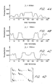
- Figure 4A - 4C depict the optical transmission characteristics for selected wavelengths of an exemplary rotational filter made in accordance with the present invention having only 17 optical coating layers. As illustrated in Figures 4A - 4C, the transmission characteristic is not as precise as the transmission characteristic of the filter represented in Figure 5.
- the dichroic filter of the present invention has several pass-bands for each wavelength depicted. In addition, outside the pass-bands, the transmission does not fall completely to zero, as with the conventional precision filters. The reduced precision in the passbands is due to the reduced number of layers in the filter.
- the reduced precision explained above is not limited to rotational dichroic filters, but could also be advantageous with dichroic filters that are vibrated (e.g., through oscillation or the like), and for any other optical filter which conventionally involves high precision in the pass-bands.
- the decreased precision of the filter of the present invention is accommodated with signal processing as further explained below to obtain the required precision. In this manner, the cost of the filter can be reduced.
- a conventional rotational filter could be fabricated with far fewer layers, but using conventional layering techniques such that the filter increases in thickness through the entire revolution of the filter.
- the method of fabrication disclosed herein could be used to form a rotational filter with conventional precision (e.g., many layers) at reduced manufacturing costs due to the improved manufacturing method.
- a flat substrate 110 ( Figure 2) is coated with optical coatings of increasing thickness to form a wedge-shaped coated layer 111.
- the thickness of the optical coating 111 has been exaggerated, and in practical applications the thickness of the optical layer 111 varies from roughly 1.66 micrometers to about 3.33 micrometers, with an average thickness of about 2.35 micrometers. It should also be understood that these thicknesses are approximate and may vary depending upon the index of refraction of the layer materials. Therefore, in accordance with one aspect of the present invention, the optical coatings which define the filter are applied across a substrate rather than continually applying coatings circumferentially, thus, significantly reducing the cost of the filter. The filter at this point provides a dichroic filter which could be used in oscillating filter type applications.
- a cylindrical portion 112 is cut from the wedge-shaped slab formed by the optical layer 111 together with the substrate 110.
- a cylindrical aperture is then formed in the center of the cylindrical portion 112 to form a mounting hole.
- an optically opaque strip such as a brass strip 122 over a portion of the optical filter disk 120.
- the brass strip provides a zero-transmission reference portion of the disc 120 which may be helpful for noise cancellation in certain signal processing applications.
- the method may, in practice, involve first cutting the substrate into a disk. Thereafter, the optical coatings are applied onto the disk as though the disk were still square so that the excess falls onto the platform (not shown) supporting the disk within the vacuum tank. In this manner the wedge is formed on the surface of the disk 120 as shown in Figure 2.
- the disk 120 does not continually increase in thickness through the entire circumference of the wheel but increases in thickness and then decreases in thickness.
- both halves of the circumference can be utilized as further described below.
- a minimal number of optical coating layers are deposited. In one preferred embodiment, only 17 layers are necessary to obtain the desired resolution.
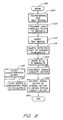
- FIG. 6 is a data flow diagram which details the method used to compensate for the imprecision of the filter made in accordance with the-present invention. It should be understood, however, that prior to run-time, initialization is performed.
- the initialization is performed at the factory or other time prior to use.
- a filter characteristics matrix is constructed, as described in greater detail below with reference to Figure 7.
- the filter characteristics matrix represents the transmission characteristics of the dichroic filter 120 at different portions of the filter 120 and for various wavelengths of light.
- the filter characteristics matrix is used in order to extract portions of the electrical signal generated by a detector which are due simply to the optical attenuation caused by the filter 120. In other words, by knowing the filter characteristics, the impression of the filter can be accounted for.
- the filter characteristic matrix is a two-dimensional matrix.
- the filter characteristic matrix includes one column for each wavelength of light which is characterized and one row for each position (rotational in the present invention) of the filter 120, at which characterization (of the filter characteristic) is performed.
- the filter characteristic matrix includes 16 columns and 256 rows when 16 wavelengths are characterized and 256 positions of the filter 120 are defined. It should be understood here that it is not necessary that 16 different wavelengths be used; the use of additional wavelengths is particularly advantageous for increasing the signal-to-noise ratio.
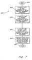
- Figures 4A-4D together with Figure 7, illustrate in greater detail, the method employed to obtain the filter characteristic matrix.
- the derivation routine is illustrated in Figure 7 and starts with a begin block 800.
- the activity blocks 830-845 together with Figures 4A-4D, illustrate the method used in accordance with the present invention to construct the filter characteristics matrix.
- the filter 120 reflects and transmits optical radiation in different proportions for different wavelengths at different places on the filter disk 120. This is clearly illustrated in Figure 4A-4C, wherein Figure 4A represents the optical transmission of fight at a wavelength of 850 nanometers plotted versus each of a possible 256 disk rotational positions (for one embodiment).
- Figure 4B depicts the optical transmission characteristics of light at 1,150 nanometers over the same 256 rotational positions of the disk 120.
- Figure 4C depicts a plot of the optical transmission of light at 1,350 nanometers through the disk filter 120 at each of the 256 rotational positions of the disk 120.
- the optical transmission characteristics of the filter 120 are described for 256 rotational positions at each of 16 wavelengths between 850 nanometers and 1,400 nanometers.
- a filter characteristic matrix may be constructed, as shown in Figure 40.
- the filter characteristic matrix designated in Figure 40 as F( ⁇ , ⁇ ) includes 256 rows and 16 columns.
- Each column of the filter characteristic matrix comprises the spectral transmission characteristics of the disk 120 at each of the 256 rotational positions of the disk 120 for the selected wavelength for that column.
- the filter 120 is illuminated at a first rotational position over each of the 16 wavelengths to obtain spectral transmission coefficients for each of the 16 wavelengths, as indicated within an activity block 830.
- This method is carried on for each of the possible rotational positions of the disk 120 until, as indicated within an activity block 840, the filter is illuminated at the "mth," or last, rotational position (i.e., position 256) of the disk filter 120 over the 16 selected wavelengths to obtain the spectral transmission coefficients for the last rotational position.
- the rotational positions will be precise from revolution to revolution of the disk 120.
- a computer disc motor with salient poles and run at a constant speed could be used provided that phase dithers are minimized to less than one part in 256.
- the filter characteristics matrix is constructed, as indicated within an activity block 845.
- Figure 3 illustrates the use of the filter 120 in a system for monitoring blood constituents.
- Figure 6 illustrates a general flow diagram for the steps of accounting for the imprecision in the filter to obtain the characteristics of a medium under test.
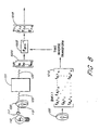
- Figure 8 illustrates a general functional diagram of the process of accounting for filter imprecision through signal processing.
- the start of processing is represented in a begin block 300.
- housekeeping and self-testing procedures are performed, as represented in an activity block 305.
- housekeeping and self testing involves boot operations and conventional initialization a self testing. For example, the system first determines if there is a sufficient signal intensity to take an accurate reading.
- the light source 110 ( Figures 3 and 8) is activated to transmit light 115 through the filter 120, as represented in an activity block 310.
- the light source 110 is activated while no test medium 131 is interposed between the filter 120 and the detector 140.
- the light which is detected by a detector 140 ( Figure 3) represents a baseline light intensity (I 0 ) which can be used as a test to insure that a bulb which is too dim or too bright is not inserted as a replacement bulb for example.
- a lens 117 ( Figure 8) can be provided between the light source and the filter 120 to provide focused light 115 on the filter 120.
- the medium 131 under test is inserted as indicated in an activity block 312.
- the light which is incident upon the detector 140 is converted to an electrical signal and this signal is amplified in a pre-amp (not shown), filtered with the band pass filter (not shown), and sampled by an analog-to-digital converter 142. Since the filter 120 is rotating (at approximately 78.125 revolutions per second in one actual embodiment, although other rotational rates could be advantageous as called for by the particular application), samples of the electrical signal output by the detector 140 are indicative of the light intensity detected at various rotational positions of the filter 120. In one advantageous embodiment, one complete rotation (i.e., 360°) of the filter 120 corresponds to 512 digital samples. That is, 512 samples are taken within the period corresponding to one revolution of the filter 120.
- the filter 120 constructed in accordance with the present invention includes redundant regions within an entire revolution.
- the filter 120 is symmetrically layered so that the first half-revolution of the filter provides a mirror of the signal of the second half-revolution of the filter 120. That is to say, as depicted in Figure 2, the filter is formed in a wedge shape so that the thickness in one direction is constant and the thickness in the perpendicular direction increases linearly.
- the second half-revolution of the filter 120 is redundant. For this reason, digital samples taken for one-half of the revolution of the filter 120 could be discarded so that in each rotation of the filter 120 there are 256 samples used for purposes of digital signal processing rather than 512 samples in the embodiment described above.
- all 512 samples can be used for processing by averaging corresponding values.
- the redundant half of the filter may be used for filter and source calibration. Each of the 256 samples (if only half are used) represents a different portion of the filter 120 having different optical transmission characteristics.
- the filter 120 is specially designed to include an opaque strip (i.e., the brass strip 122).
- the digital signal processor 145 detects when the opaque strip 122 of the filter 120 is interposed between the light 115 and the detector 140 by monitoring the intensity output from the detector 140. This intensity is effectively zero when the light is blocked by the opaque strip 122. Since the opaque strip 122 blocks substantially all of the optical radiation transmitted from the source 110, any signal output from the optical detector 140 when the light is blocked (e.g., from ambient light, thermal effects, etc.), will be interpreted as electrical noise which is not due to either the spectral absorption characteristics of the medium under test 131 or the spectral transmission characteristics of the filter 120.
- control passes from the activity block 315 to an activity block 323.
- the signal is divided by I 0 to normalize the signaL
- the normalized signal is subsequently processed within an activity block 325 to construct a signal intensity matrix, or vector, from the sample values obtained within the activity block 315 (taking into consideration the subtraction of the electrical noise, and the signal normalization performed in the activity block 323)
- Figure 8 illustrates a signal intensity matrix I ⁇ m.
- the signal intensity matrix 1000 ( Figure 8) is a one column matrix (sometimes referred to as a vector) including 256 signal intensity values (e.g., one value for each sampled rotational position of the filter 120 in the present embodiment).
- the signal intensity vector 1000 is obtained by direct measurement of the optical signal which passes through both the filter 120 and the test medium 131 and is detected by the optical detector 140.
- the values used to form the signal intensity vector 1000 are taken from the amplitude of the signals output from the detector 140 after subtraction of the noise from each sample.
- ⁇ 1 will correspond to the first rotational position of the filter 120
- ⁇ 2 will correspond to the second rotational position of the filter 120
- ⁇ 256 which corresponds to the last rotational position of the filter 120 before ⁇ 1 is taken again.
- I ⁇ 1 corresponds to the intensity of light detected by the optical detector 140 when the filter 120 is in the first rotational position ⁇ 1
- I ⁇ 2 corresponds to the intensity of light detected by the detector 140 when the filter 120 is in the second rotational position ⁇ 2 , etc.
- the signal intensity matrix may be used to obtain a matrix indicative only of the optical absorption characteristics of the test medium 131, as represented in activity blocks 330, 331.
- T( ⁇ ) the transmission through the test medium 131
- the transmission of light through the test medium 131 is defined as a function of the wavelength
- the transmission of light through a selected rotational position (e.g., when ⁇ 0, corresponding to 0°) of a filter 120 is maintained as a function of wavelength and is designated by the function F( ⁇ , ⁇ )
- the combination, or convolution, of the optical absorption due to the test medium 131 and the filter 120 is designated over the same wavelengths by the function I( ⁇ ).
- T( ⁇ ) from the intensity vector I( ⁇ ) and the filter transmission matrix F( ⁇ , ⁇ )
- the intensity vector I( ⁇ ) and the inverse F -1 ( ⁇ ) are multiplied.
- Equation (2) the signal intensity matrix I( ⁇ ) is equal to the product of the two dimensional filter characteristic matrix, F( ⁇ , ⁇ ), and the single column test medium matrix T( ⁇ ).
- two of the matrices are given (i.e., I( ⁇ ) and F( ⁇ , ⁇ )).
- T( ⁇ ) which represents the optical transmission characteristics of the test medium 131 for the 16 selected wavelengths between 850 nanometers and 1,400 nanometers, may be obtained by simply multiplying the inverse of the filter characteristic matrix, designated as F -1 ( ⁇ , ⁇ ), by the signal intensity matrix, I( ⁇ ), using conventional matrix inversion and multiplication techniques, as shown below.
- the signal intensity matrix 1000 is multiplied by the inverse of the filter characteristic matrix 1010 as indicated within a block 1005.
- the filter characteristic matrix 1010 is derived from an analysis of the filter 120, as described above.
- the inverse transform of the filter characteristic matrix 1010 is multiplied by the signal intensity vector 1000 to obtain the optical frequency response matrix, or transmission vector, 1015.
- One particularly advantageous application of the filter of the present invention involves monitoring blood glucose levels within a patient, such as a diabetic, without requiring the extraction of blood. This application is described briefly below.
- the filter 120 further includes the optically opaque strip 122 which may, for example, comprise brass or some other metal which is deposited radially outward from the center of the filter disk 120.
- the opaque strip provides a "0" location indicator and zero optical intensity, or electrical offset.
- the filter disk 120 is driven in a circular motion by a smooth, disk drive motor in one preferred embodiment; however, a stepper motor could be used advantageously for its known phase condition.
- Filtered optical radiation 125 passes from the filter 120 through a fleshy medium, perfused with blood such as a finger tip 130. In some applications, it may be desirable to provide a focusing lens, or other optical conduit, between the filter 120 and the finger 130.
- the light which passes through the finger 130 is detected by a detector 140. In general, the detection signal is conditioned and converted to digital form in the analog to digital conversion circuit 142.
- the digital signal processor 145 accepts the digital signals and accommodates for the imprecision in the dichroic filter.
- the finger 130 is known to include a fingernail, skin, bones, flesh, and blood.
- the blood itself primarily comprises water, oxyhemoglobin, hemoglobin, lipids, protein and glucose.
- Each of these constituents within the finger e.g., nerves, muscle tissue, etc.
- the absorption of optical radiation through a nonhomogeneous medium typically follows well defined laws in relation to the optical characteristics of each of the constituents taken separately. Approximations to these laws are expressed in the equations for Beer-Lambert's law, where low scattering applications most closely follow the Beer-Lambert equations.
- the light 135 which passes through the finger 130 is incident upon the optical detector 140.
- the optical detector 140 generates an electrical signal proportional to the overall intensity of the light 135.
- the filter 120 constructed in accordance with the present invention includes redundant regions within an entire revolution.
- the filter 120 is symmetrically layered so that the first half-revolution of the filter is substantially symmetrical to the signal of the second half-revolution of the filter 120. That is to say, as depicted in Figure 13, the filter is formed in a wedge shape so that the thickness in one direction is constant and the thickness in the perpendicular direction increases linearly.
- the second half-revolution of the filter 120 is redundant. For this reason, digital samples taken for one-half of the revolution of the filter 120 could be discarded so that in each rotation of the filter 120 there are 128 samples used for purposes of digital signal processing rather than 256 samples in one embodiment.
- the redundant half of the filter may be used for filter and source calibration.
- Each of the 128 samples (if only half are used) represents a different portion of the filter 120 having different optical transmission characteristics.
- the production specifications for the filter 120 are as follows: SIZE 20 mm wide x 20 mm wavelength span, linear multilayer coating SUBSTRATE 25 mm 0D glass disc with 7.5 mm shaft hole in center WAVELENGTH PASSED 700-1400 nanometers 1/2 BANDWIDTH 50 to 200 nanometers, bands may repeat BLOCKING none ENVIRONMENT Survive condensing humidity, 0-70 c
- the pass band edges are produced so as to differentiate a 20 nanometer band edge.
- Blocking requirements outside of the window are not critical. They may be limited by band-edge materials such as RG660, RG700, or semiconductors, or 0-H bands typically found in glass below 7100 cm -1 .
- the filter will not have a window narrower than 8,000 to 11,000 cm -1 or about 910 to 1,250 nm.
- the bandwidth is advantageously wider than 200 cm -1 , and the band edge is advantageously narrower than 200 cm -1 .
- the transmission maximum of the primary band is advantageously above 80%, and the transmission minimum is advantageously below 20%. Any other bands should be repeatable, unit to unit; but if they are not, a calibration ROM could be used in accordance with the DSP to perform initial calibration of individual filters.
- the linear filter is advantageously rotated about its center at less than 4,800 RPM for portable in vivo applications (although near 48,000 RPM might be suitable in certain industrial applications), with an aperture centered at a radius of minimum 9 mm to maximum 45 mm, with a clear aperture diameter of 1 mm to 3 mm and a numerical aperture of .12 to .40.
- the light path passes through a small circular portion traveling along an annular region of the rotating filter, causing a sinusoidal scan of the wavelengths, although they are deposited linearly.
- the linear filter is deposited on a circular substrate. Since the center is not used optically, a standard diameter shaft mounting hole is preferred; most of the present hardware in the invention use either 0.5000-.000, +.0005" diameter, or 7.5 -0.0+.1 mm. For a small filter, e.g., 20 mm diameter, bonding to the uncoated side would be considered. Note that the filter mount does not have spokes or other structural interruption of the optical path.
Landscapes
- Physics & Mathematics (AREA)
- Spectroscopy & Molecular Physics (AREA)
- General Physics & Mathematics (AREA)
- Chemical & Material Sciences (AREA)
- Life Sciences & Earth Sciences (AREA)
- Analytical Chemistry (AREA)
- Biochemistry (AREA)
- General Health & Medical Sciences (AREA)
- Health & Medical Sciences (AREA)
- Immunology (AREA)
- Pathology (AREA)
- Optics & Photonics (AREA)
- Investigating Or Analysing Materials By Optical Means (AREA)
- Spectrometry And Color Measurement (AREA)
- Optical Filters (AREA)
- Investigating Or Analysing Biological Materials (AREA)
Claims (15)
- Optisches Filter mit:einem im allgemeinen kreisförmigen Substrat mit einer oberen Fläche und einer unteren Fläche, wobei das kreisförmige Substrat eine mittig ausgebildete Halterungsöffnung aufweist, so daß das Filter um eine Welle drehbar montierbar ist; undmehreren auf der oberen Fläche des Substrats aufgebrachten optischen Schichten (111), dadurch gekennzeichnet, daß sich die Dicke der optischen Schichten (111) in einer ersten Richtung quer über die obere Fläche des Substrats linear ändert, die Dicke der Schichten (111) in einer zweiten Richtung, die sich im wesentlichen senkrecht zur ersten Richtung erstreckt, quer über die obere Fläche des Substrats im wesentlichen konstant ist, und die optischen Schichten so konfiguriert sind, daß Durchlaßcharakteristiken bereitgestellt werden, die entlang der ersten Richtung als Funktion der Wellenlänge variieren.
- Optisches System mit:einem optischen Filter nach Anspruch 1;einem Detektor (140), der so angeordnet ist, daß er auf den Detektor (140) auftreffendes und durch das optische Filter gefiltertes Licht (135) empfängt, wobei der Detektor (140) so konfiguriert ist, daß der Detektor (140) in Antwort auf das empfangene Licht ein die Summe des gesamten auftreffenden Lichts innerhalb der Antwort des Detektors (140) darstellendes Ausgangssignal erzeugt; undeinem mit dem Detektor (140) verbundenen Signalprozessor (145), wobei der Signalprozessor (145) auf das Ausgangssignal anspricht, um das Ausgangssignal in Komponentenbestandteile zu decodieren, wobei ein Teil die optische Charakteristik des auf den Detektor auftreffenden Lichts darstellt.
- Optisches Filter nach Anspruch 1, wobei die Halterungsöffnung eine zylindrische Öffnung ist, so daß das Filter um eine sich durch die Öffnung erstreckende Welle drehbar montierbar ist.
- Optisches Filter nach Anspruch 3, ferner mit einem optisch opaken radial angeordneten Streifen (122).
- Optisches Filter nach Anspruch 4, wobei 17 Schichten (111) vorgesehen sind.
- Optisches Filter nach Anspruch 1, wobei die Schichten (111) so konfiguriert sind, daß optische Durchlaßcharakteristiken bereitgestellt werden, die sich innerhalb eines Bereichs einer vollen Umdrehung des Filters entlang der ersten Richtung wiederholen.
- Optisches Filter nach Anspruch 6, wobei die Durchlaßcharakteristiken für eine erste Halbumdrehung und eine zweite Halbumdrehung des Filters im wesentlichen symmetrisch sind.
- Optisches Filter nach Anspruch 7, wobei die mehreren Schichten (111) so ausgewählt sind, daß eine spezifische Wellenlänge über die erste Halbumdrehung mehrere Durchlaßbänder aufweist.
- Optisches Filter nach einem der Ansprüche 1 oder 3 bis 8, wobei bei jeder Drehposition des Filters etwa die Hälfte des auftreffenden Lichts durch die Schichten (111) transmittiert wird.
- Optisches Filter nach einem der Ansprüche 1 oder 3 bis 8, wobei das Verhältnis der gesamten transmittierten Signalintensität zur transmittierten Signalintensität für eine von einer Lichtquelle durch das Filter transmittierte, ausgewählte Betriebswellenlänge bei jeder Drehposition des Filters im Bereich von 10 bis 100 liegt.
- Optisches Filter nach Anspruch 10, wobei die Durchlaßcharakteristiken mehrere Durchlaßbänder für mindestens eine wellenlänge aufweisen.
- Optisches Filter nach Anspruch 11, wobei die Wellenlängen im Bereich von 700 bis 1400 nm liegen.
- Optisches Filter nach Anspruch 11, wobei die Wellenlängen im Bereich von 910 bis 1250 nm liegen.
- Verfahren zum Herstellen eines drehbaren optischen Filters, wobei das Verfahren die Schritte aufweist:Bereitstellen eines im allgemeinen kreisförmigen optischen Substrats (110) mit einer oberen Fläche und einer unteren Fläche;Bereitstellen einer Halterungsöffnung in einer Mitte des Substrats (110), so daß das Filter um eine Welle drehbar montierbar ist; undAufbringen optischer Schichten (111) auf der oberen Fläche derart, daß sich die Dicke der optischen Schichten (111) in einer ersten Richtung quer über die obere Fläche linear ändert, und derart, daß die Dicke der Schichten (111) in einer zweiten Richtung, die sich im wesentlichen senkrecht zur ersten Richtung erstreckt, im wesentlichen konstant ist, wobei durch die optischen Schichten Durchlaßcharakteristiken bereitgestellt werden, die sich entlang der ersten Richtung als Funktion der Wellenlänge ändern.
- Verfahren nach Anspruch 14, ferner mit dem Schritt zum Aufbringen eines opaken Streifens (122) entlang mindestens eines Abschnitts des Substrats.
Applications Claiming Priority (3)
| Application Number | Priority Date | Filing Date | Title |
|---|---|---|---|
| US08/486,798 US5760910A (en) | 1995-06-07 | 1995-06-07 | Optical filter for spectroscopic measurement and method of producing the optical filter |
| US486798 | 1995-06-07 | ||
| PCT/US1996/008627 WO1996041218A1 (en) | 1995-06-07 | 1996-06-04 | Optical filter for spectroscopic measurement and method of producing the optical filter |
Publications (2)
| Publication Number | Publication Date |
|---|---|
| EP0830625A1 EP0830625A1 (de) | 1998-03-25 |
| EP0830625B1 true EP0830625B1 (de) | 2003-05-07 |
Family
ID=23933284
Family Applications (1)
| Application Number | Title | Priority Date | Filing Date |
|---|---|---|---|
| EP96918004A Expired - Lifetime EP0830625B1 (de) | 1995-06-07 | 1996-06-04 | Optisches filter für spektroskopische messungen und verfahren zur herstellung des filters |
Country Status (9)
| Country | Link |
|---|---|
| US (3) | US5760910A (de) |
| EP (1) | EP0830625B1 (de) |
| JP (1) | JPH11507143A (de) |
| CN (1) | CN1192808A (de) |
| AT (1) | ATE239924T1 (de) |
| AU (1) | AU706049B2 (de) |
| CA (1) | CA2221859A1 (de) |
| DE (1) | DE69628005T2 (de) |
| WO (1) | WO1996041218A1 (de) |
Families Citing this family (491)
| Publication number | Priority date | Publication date | Assignee | Title |
|---|---|---|---|---|
| MX9702434A (es) * | 1991-03-07 | 1998-05-31 | Masimo Corp | Aparato de procesamiento de señales. |
| US5490505A (en) | 1991-03-07 | 1996-02-13 | Masimo Corporation | Signal processing apparatus |
| AU658177B2 (en) * | 1991-03-07 | 1995-04-06 | Masimo Corporation | Signal processing apparatus and method |
| US5638818A (en) * | 1991-03-21 | 1997-06-17 | Masimo Corporation | Low noise optical probe |
| US6371921B1 (en) * | 1994-04-15 | 2002-04-16 | Masimo Corporation | System and method of determining whether to recalibrate a blood pressure monitor |
| US8019400B2 (en) | 1994-10-07 | 2011-09-13 | Masimo Corporation | Signal processing apparatus |
| EP1905352B1 (de) | 1994-10-07 | 2014-07-16 | Masimo Corporation | Signalverarbeitungsmethode |
| US6517283B2 (en) | 2001-01-16 | 2003-02-11 | Donald Edward Coffey | Cascading chute drainage system |
| US5760910A (en) * | 1995-06-07 | 1998-06-02 | Masimo Corporation | Optical filter for spectroscopic measurement and method of producing the optical filter |
| US5758644A (en) | 1995-06-07 | 1998-06-02 | Masimo Corporation | Manual and automatic probe calibration |
| US6931268B1 (en) | 1995-06-07 | 2005-08-16 | Masimo Laboratories, Inc. | Active pulse blood constituent monitoring |
| US6027452A (en) | 1996-06-26 | 2000-02-22 | Vital Insite, Inc. | Rapid non-invasive blood pressure measuring device |
| US6018673A (en) | 1996-10-10 | 2000-01-25 | Nellcor Puritan Bennett Incorporated | Motion compatible sensor for non-invasive optical blood analysis |
| US6002952A (en) | 1997-04-14 | 1999-12-14 | Masimo Corporation | Signal processing apparatus and method |
| US6229856B1 (en) | 1997-04-14 | 2001-05-08 | Masimo Corporation | Method and apparatus for demodulating signals in a pulse oximetry system |
| US6174648B1 (en) * | 1997-07-08 | 2001-01-16 | Oki Electric Industry Co., Ltd. | Optical filter fabrication method using fiber holder with spiral groove and phase mask with spiral diffraction grating |
| FR2765971B1 (fr) * | 1997-07-10 | 1999-09-24 | Reosc | Filtre optique a transmission spectrale variable et largeur de bande spectrale constante |
| EP1229355B1 (de) * | 1997-10-20 | 2006-01-18 | Nippon Telegraph and Telephone Corporation | Vorrichtung zur Erzeugung optischer Pakete mit scheibenförmigem abstimmbarem optischen Filter |
| US6525386B1 (en) * | 1998-03-10 | 2003-02-25 | Masimo Corporation | Non-protruding optoelectronic lens |
| JP2002516689A (ja) * | 1998-06-03 | 2002-06-11 | マシモ・コーポレイション | ステレオパルスオキシメータ |
| US7245953B1 (en) | 1999-04-12 | 2007-07-17 | Masimo Corporation | Reusable pulse oximeter probe and disposable bandage apparatii |
| USRE41912E1 (en) | 1998-10-15 | 2010-11-02 | Masimo Corporation | Reusable pulse oximeter probe and disposable bandage apparatus |
| US6721585B1 (en) | 1998-10-15 | 2004-04-13 | Sensidyne, Inc. | Universal modular pulse oximeter probe for use with reusable and disposable patient attachment devices |
| US6091502A (en) * | 1998-12-23 | 2000-07-18 | Micronics, Inc. | Device and method for performing spectral measurements in flow cells with spatial resolution |
| US6463311B1 (en) | 1998-12-30 | 2002-10-08 | Masimo Corporation | Plethysmograph pulse recognition processor |
| US6684090B2 (en) | 1999-01-07 | 2004-01-27 | Masimo Corporation | Pulse oximetry data confidence indicator |
| JP3361305B2 (ja) * | 1999-01-14 | 2003-01-07 | 日本電信電話株式会社 | 光 源 |
| US6770028B1 (en) | 1999-01-25 | 2004-08-03 | Masimo Corporation | Dual-mode pulse oximeter |
| US20020140675A1 (en) | 1999-01-25 | 2002-10-03 | Ali Ammar Al | System and method for altering a display mode based on a gravity-responsive sensor |
| US6360114B1 (en) | 1999-03-25 | 2002-03-19 | Masimo Corporation | Pulse oximeter probe-off detector |
| US6675031B1 (en) | 1999-04-14 | 2004-01-06 | Mallinckrodt Inc. | Method and circuit for indicating quality and accuracy of physiological measurements |
| US6515273B2 (en) * | 1999-08-26 | 2003-02-04 | Masimo Corporation | System for indicating the expiration of the useful operating life of a pulse oximetry sensor |
| JP2001111488A (ja) * | 1999-10-01 | 2001-04-20 | Nippon Telegr & Teleph Corp <Ntt> | Wdm信号分波装置 |
| US6377829B1 (en) | 1999-12-09 | 2002-04-23 | Masimo Corporation | Resposable pulse oximetry sensor |
| US6950687B2 (en) | 1999-12-09 | 2005-09-27 | Masimo Corporation | Isolation and communication element for a resposable pulse oximetry sensor |
| US8224412B2 (en) | 2000-04-17 | 2012-07-17 | Nellcor Puritan Bennett Llc | Pulse oximeter sensor with piece-wise function |
| ES2469805T3 (es) | 2000-04-17 | 2014-06-20 | Covidien Lp | Sensor de pulsiox�metro con función a tramos |
| US6430525B1 (en) | 2000-06-05 | 2002-08-06 | Masimo Corporation | Variable mode averager |
| US6640116B2 (en) * | 2000-08-18 | 2003-10-28 | Masimo Corporation | Optical spectroscopy pathlength measurement system |
| EP1309270B1 (de) | 2000-08-18 | 2009-07-01 | Masimo Corporation | Pulsoximeter mit zwei betriebsarten |
| US20020083461A1 (en) | 2000-11-22 | 2002-06-27 | Hutcheson Stewart Douglas | Method and system for providing interactive services over a wireless communications network |
| US6785002B2 (en) * | 2001-03-16 | 2004-08-31 | Optical Coating Laboratory, Inc. | Variable filter-based optical spectrometer |
| WO2002089664A2 (en) | 2001-05-03 | 2002-11-14 | Masimo Corporation | Flex circuit shielded optical sensor and method of fabricating the same |
| US6850787B2 (en) | 2001-06-29 | 2005-02-01 | Masimo Laboratories, Inc. | Signal component processor |
| US6697658B2 (en) | 2001-07-02 | 2004-02-24 | Masimo Corporation | Low power pulse oximeter |
| EP1273928A1 (de) * | 2001-07-06 | 2003-01-08 | Leica Geosystems AG | Verfahren und Vorrichtung zur Unterdrückung elektromagnetischer Hintergrundstrahlung in einem Bild |
| US6678082B2 (en) | 2001-09-12 | 2004-01-13 | Harris Corporation | Electro-optical component including a fluorinated poly(phenylene ether ketone) protective coating and related methods |
| US6748254B2 (en) | 2001-10-12 | 2004-06-08 | Nellcor Puritan Bennett Incorporated | Stacked adhesive optical sensor |
| US20030212312A1 (en) * | 2002-01-07 | 2003-11-13 | Coffin James P. | Low noise patient cable |
| US6934570B2 (en) * | 2002-01-08 | 2005-08-23 | Masimo Corporation | Physiological sensor combination |
| US6822564B2 (en) | 2002-01-24 | 2004-11-23 | Masimo Corporation | Parallel measurement alarm processor |
| US7355512B1 (en) | 2002-01-24 | 2008-04-08 | Masimo Corporation | Parallel alarm processor |
| WO2003065557A2 (en) * | 2002-01-25 | 2003-08-07 | Masimo Corporation | Power supply rail controller |
| US6623142B1 (en) * | 2002-02-15 | 2003-09-23 | Delphi Technologies, Inc. | Method and apparatus for correcting optical non-uniformities in a light emitting diode |
| WO2003071939A1 (en) * | 2002-02-22 | 2003-09-04 | Masimo Corporation | Active pulse spectraphotometry |
| US7509494B2 (en) * | 2002-03-01 | 2009-03-24 | Masimo Corporation | Interface cable |
| US6850788B2 (en) | 2002-03-25 | 2005-02-01 | Masimo Corporation | Physiological measurement communications adapter |
| US7096054B2 (en) * | 2002-08-01 | 2006-08-22 | Masimo Corporation | Low noise optical housing |
| US7274955B2 (en) * | 2002-09-25 | 2007-09-25 | Masimo Corporation | Parameter compensated pulse oximeter |
| US7142901B2 (en) * | 2002-09-25 | 2006-11-28 | Masimo Corporation | Parameter compensated physiological monitor |
| JP3915651B2 (ja) * | 2002-10-09 | 2007-05-16 | 株式会社島津製作所 | 複数の蛍光物質を含む試料の分析方法及び装置 |
| US7190986B1 (en) | 2002-10-18 | 2007-03-13 | Nellcor Puritan Bennett Inc. | Non-adhesive oximeter sensor for sensitive skin |
| WO2004047631A2 (en) * | 2002-11-22 | 2004-06-10 | Masimo Laboratories, Inc. | Blood parameter measurement system |
| US6970792B1 (en) | 2002-12-04 | 2005-11-29 | Masimo Laboratories, Inc. | Systems and methods for determining blood oxygen saturation values using complex number encoding |
| US7919713B2 (en) | 2007-04-16 | 2011-04-05 | Masimo Corporation | Low noise oximetry cable including conductive cords |
| US7225006B2 (en) | 2003-01-23 | 2007-05-29 | Masimo Corporation | Attachment and optical probe |
| US6920345B2 (en) | 2003-01-24 | 2005-07-19 | Masimo Corporation | Optical sensor including disposable and reusable elements |
| US20050055276A1 (en) * | 2003-06-26 | 2005-03-10 | Kiani Massi E. | Sensor incentive method |
| JP4223873B2 (ja) * | 2003-07-02 | 2009-02-12 | 日本電信電話株式会社 | 波長可変光フィルタ及びその作製方法 |
| US7003338B2 (en) | 2003-07-08 | 2006-02-21 | Masimo Corporation | Method and apparatus for reducing coupling between signals |
| US7500950B2 (en) | 2003-07-25 | 2009-03-10 | Masimo Corporation | Multipurpose sensor port |
| US7254431B2 (en) * | 2003-08-28 | 2007-08-07 | Masimo Corporation | Physiological parameter tracking system |
| US7254434B2 (en) * | 2003-10-14 | 2007-08-07 | Masimo Corporation | Variable pressure reusable sensor |
| US7483729B2 (en) * | 2003-11-05 | 2009-01-27 | Masimo Corporation | Pulse oximeter access apparatus and method |
| US7373193B2 (en) * | 2003-11-07 | 2008-05-13 | Masimo Corporation | Pulse oximetry data capture system |
| US7130320B2 (en) * | 2003-11-13 | 2006-10-31 | Mitutoyo Corporation | External cavity laser with rotary tuning element |
| US7280858B2 (en) * | 2004-01-05 | 2007-10-09 | Masimo Corporation | Pulse oximetry sensor |
| US7371981B2 (en) | 2004-02-20 | 2008-05-13 | Masimo Corporation | Connector switch |
| US7162288B2 (en) | 2004-02-25 | 2007-01-09 | Nellcor Purtain Bennett Incorporated | Techniques for detecting heart pulses and reducing power consumption in sensors |
| US7438683B2 (en) * | 2004-03-04 | 2008-10-21 | Masimo Corporation | Application identification sensor |
| US7415297B2 (en) * | 2004-03-08 | 2008-08-19 | Masimo Corporation | Physiological parameter system |
| US20050234317A1 (en) * | 2004-03-19 | 2005-10-20 | Kiani Massi E | Low power and personal pulse oximetry systems |
| WO2005115737A2 (en) * | 2004-03-22 | 2005-12-08 | Quantaspec Inc. | System and method for detecting and identifying an analyte |
| WO2005096922A1 (en) * | 2004-03-31 | 2005-10-20 | Masimo Corporation | Physiological assessment system |
| CA2464029A1 (en) | 2004-04-08 | 2005-10-08 | Valery Telfort | Non-invasive ventilation monitor |
| US7343186B2 (en) | 2004-07-07 | 2008-03-11 | Masimo Laboratories, Inc. | Multi-wavelength physiological monitor |
| US9341565B2 (en) | 2004-07-07 | 2016-05-17 | Masimo Corporation | Multiple-wavelength physiological monitor |
| US7937128B2 (en) * | 2004-07-09 | 2011-05-03 | Masimo Corporation | Cyanotic infant sensor |
| US7254429B2 (en) | 2004-08-11 | 2007-08-07 | Glucolight Corporation | Method and apparatus for monitoring glucose levels in a biological tissue |
| US8036727B2 (en) | 2004-08-11 | 2011-10-11 | Glt Acquisition Corp. | Methods for noninvasively measuring analyte levels in a subject |
| US7976472B2 (en) | 2004-09-07 | 2011-07-12 | Masimo Corporation | Noninvasive hypovolemia monitor |
| WO2006039350A1 (en) * | 2004-09-29 | 2006-04-13 | Masimo Corporation | Multiple key position plug |
| USD566282S1 (en) | 2005-02-18 | 2008-04-08 | Masimo Corporation | Stand for a portable patient monitor |
| US20060189871A1 (en) | 2005-02-18 | 2006-08-24 | Ammar Al-Ali | Portable patient monitor |
| USD554263S1 (en) | 2005-02-18 | 2007-10-30 | Masimo Corporation | Portable patient monitor |
| US7596398B2 (en) | 2005-03-01 | 2009-09-29 | Masimo Laboratories, Inc. | Multiple wavelength sensor attachment |
| US7937129B2 (en) * | 2005-03-21 | 2011-05-03 | Masimo Corporation | Variable aperture sensor |
| AU2006235535A1 (en) | 2005-04-13 | 2006-10-19 | Glt Acquisition Corp. | Method for data reduction and calibration of an OCT-based blood glucose monitor |
| US12014328B2 (en) | 2005-07-13 | 2024-06-18 | Vccb Holdings, Inc. | Medicine bottle cap with electronic embedded curved display |
| US7657294B2 (en) | 2005-08-08 | 2010-02-02 | Nellcor Puritan Bennett Llc | Compliant diaphragm medical sensor and technique for using the same |
| US7657295B2 (en) | 2005-08-08 | 2010-02-02 | Nellcor Puritan Bennett Llc | Medical sensor and technique for using the same |
| US7590439B2 (en) | 2005-08-08 | 2009-09-15 | Nellcor Puritan Bennett Llc | Bi-stable medical sensor and technique for using the same |
| US20070073116A1 (en) * | 2005-08-17 | 2007-03-29 | Kiani Massi E | Patient identification using physiological sensor |
| US20070060808A1 (en) | 2005-09-12 | 2007-03-15 | Carine Hoarau | Medical sensor for reducing motion artifacts and technique for using the same |
| US7904130B2 (en) | 2005-09-29 | 2011-03-08 | Nellcor Puritan Bennett Llc | Medical sensor and technique for using the same |
| US8092379B2 (en) | 2005-09-29 | 2012-01-10 | Nellcor Puritan Bennett Llc | Method and system for determining when to reposition a physiological sensor |
| US7869850B2 (en) | 2005-09-29 | 2011-01-11 | Nellcor Puritan Bennett Llc | Medical sensor for reducing motion artifacts and technique for using the same |
| US7899510B2 (en) | 2005-09-29 | 2011-03-01 | Nellcor Puritan Bennett Llc | Medical sensor and technique for using the same |
| US7555327B2 (en) | 2005-09-30 | 2009-06-30 | Nellcor Puritan Bennett Llc | Folding medical sensor and technique for using the same |
| US8233954B2 (en) | 2005-09-30 | 2012-07-31 | Nellcor Puritan Bennett Llc | Mucosal sensor for the assessment of tissue and blood constituents and technique for using the same |
| US8062221B2 (en) | 2005-09-30 | 2011-11-22 | Nellcor Puritan Bennett Llc | Sensor for tissue gas detection and technique for using the same |
| US7881762B2 (en) | 2005-09-30 | 2011-02-01 | Nellcor Puritan Bennett Llc | Clip-style medical sensor and technique for using the same |
| US7483731B2 (en) | 2005-09-30 | 2009-01-27 | Nellcor Puritan Bennett Llc | Medical sensor and technique for using the same |
| US7486979B2 (en) | 2005-09-30 | 2009-02-03 | Nellcor Puritan Bennett Llc | Optically aligned pulse oximetry sensor and technique for using the same |
| US7962188B2 (en) | 2005-10-14 | 2011-06-14 | Masimo Corporation | Robust alarm system |
| US7530942B1 (en) | 2005-10-18 | 2009-05-12 | Masimo Corporation | Remote sensing infant warmer |
| EP1956968B1 (de) | 2005-11-29 | 2020-04-15 | Masimo Corporation | Optischer sensor mit einweg- und wiederverwendbaren elementen |
| EP2399516B1 (de) | 2005-11-30 | 2017-03-01 | Toshiba Medical Systems Corporation | Verfahren zur nicht invasiven Messung von Glukose und Vorrichtung zur nicht invasiven Messung von Glukose |
| US7990382B2 (en) * | 2006-01-03 | 2011-08-02 | Masimo Corporation | Virtual display |
| US8182443B1 (en) | 2006-01-17 | 2012-05-22 | Masimo Corporation | Drug administration controller |
| US20070244377A1 (en) * | 2006-03-14 | 2007-10-18 | Cozad Jenny L | Pulse oximeter sleeve |
| US8219172B2 (en) | 2006-03-17 | 2012-07-10 | Glt Acquisition Corp. | System and method for creating a stable optical interface |
| US8073518B2 (en) | 2006-05-02 | 2011-12-06 | Nellcor Puritan Bennett Llc | Clip-style medical sensor and technique for using the same |
| US7477924B2 (en) | 2006-05-02 | 2009-01-13 | Nellcor Puritan Bennett Llc | Medical sensor and technique for using the same |
| US7522948B2 (en) | 2006-05-02 | 2009-04-21 | Nellcor Puritan Bennett Llc | Medical sensor and technique for using the same |
| US9176141B2 (en) | 2006-05-15 | 2015-11-03 | Cercacor Laboratories, Inc. | Physiological monitor calibration system |
| US8998809B2 (en) | 2006-05-15 | 2015-04-07 | Cercacor Laboratories, Inc. | Systems and methods for calibrating minimally invasive and non-invasive physiological sensor devices |
| US7941199B2 (en) | 2006-05-15 | 2011-05-10 | Masimo Laboratories, Inc. | Sepsis monitor |
| WO2007140478A2 (en) | 2006-05-31 | 2007-12-06 | Masimo Corporation | Respiratory monitoring |
| US10188348B2 (en) | 2006-06-05 | 2019-01-29 | Masimo Corporation | Parameter upgrade system |
| US8145288B2 (en) | 2006-08-22 | 2012-03-27 | Nellcor Puritan Bennett Llc | Medical sensor for reducing signal artifacts and technique for using the same |
| US8315683B2 (en) * | 2006-09-20 | 2012-11-20 | Masimo Corporation | Duo connector patient cable |
| USD587657S1 (en) | 2007-10-12 | 2009-03-03 | Masimo Corporation | Connector assembly |
| USD614305S1 (en) | 2008-02-29 | 2010-04-20 | Masimo Corporation | Connector assembly |
| US8457707B2 (en) | 2006-09-20 | 2013-06-04 | Masimo Corporation | Congenital heart disease monitor |
| US8219170B2 (en) | 2006-09-20 | 2012-07-10 | Nellcor Puritan Bennett Llc | System and method for practicing spectrophotometry using light emitting nanostructure devices |
| USD609193S1 (en) | 2007-10-12 | 2010-02-02 | Masimo Corporation | Connector assembly |
| US20080103375A1 (en) * | 2006-09-22 | 2008-05-01 | Kiani Massi E | Patient monitor user interface |
| US8175671B2 (en) | 2006-09-22 | 2012-05-08 | Nellcor Puritan Bennett Llc | Medical sensor for reducing signal artifacts and technique for using the same |
| US8195264B2 (en) | 2006-09-22 | 2012-06-05 | Nellcor Puritan Bennett Llc | Medical sensor for reducing signal artifacts and technique for using the same |
| US8840549B2 (en) | 2006-09-22 | 2014-09-23 | Masimo Corporation | Modular patient monitor |
| US8396527B2 (en) | 2006-09-22 | 2013-03-12 | Covidien Lp | Medical sensor for reducing signal artifacts and technique for using the same |
| US9161696B2 (en) | 2006-09-22 | 2015-10-20 | Masimo Corporation | Modular patient monitor |
| US7869849B2 (en) | 2006-09-26 | 2011-01-11 | Nellcor Puritan Bennett Llc | Opaque, electrically nonconductive region on a medical sensor |
| US7574245B2 (en) | 2006-09-27 | 2009-08-11 | Nellcor Puritan Bennett Llc | Flexible medical sensor enclosure |
| US7890153B2 (en) | 2006-09-28 | 2011-02-15 | Nellcor Puritan Bennett Llc | System and method for mitigating interference in pulse oximetry |
| US7796403B2 (en) | 2006-09-28 | 2010-09-14 | Nellcor Puritan Bennett Llc | Means for mechanical registration and mechanical-electrical coupling of a faraday shield to a photodetector and an electrical circuit |
| US7476131B2 (en) | 2006-09-29 | 2009-01-13 | Nellcor Puritan Bennett Llc | Device for reducing crosstalk |
| US8175667B2 (en) | 2006-09-29 | 2012-05-08 | Nellcor Puritan Bennett Llc | Symmetric LED array for pulse oximetry |
| US7684842B2 (en) | 2006-09-29 | 2010-03-23 | Nellcor Puritan Bennett Llc | System and method for preventing sensor misuse |
| US7680522B2 (en) | 2006-09-29 | 2010-03-16 | Nellcor Puritan Bennett Llc | Method and apparatus for detecting misapplied sensors |
| US8068891B2 (en) | 2006-09-29 | 2011-11-29 | Nellcor Puritan Bennett Llc | Symmetric LED array for pulse oximetry |
| US8265723B1 (en) | 2006-10-12 | 2012-09-11 | Cercacor Laboratories, Inc. | Oximeter probe off indicator defining probe off space |
| JP2010506614A (ja) | 2006-10-12 | 2010-03-04 | マシモ コーポレイション | 灌流指数平滑化装置 |
| US9861305B1 (en) | 2006-10-12 | 2018-01-09 | Masimo Corporation | Method and apparatus for calibration to reduce coupling between signals in a measurement system |
| US7880626B2 (en) | 2006-10-12 | 2011-02-01 | Masimo Corporation | System and method for monitoring the life of a physiological sensor |
| US8255026B1 (en) | 2006-10-12 | 2012-08-28 | Masimo Corporation, Inc. | Patient monitor capable of monitoring the quality of attached probes and accessories |
| US9192329B2 (en) | 2006-10-12 | 2015-11-24 | Masimo Corporation | Variable mode pulse indicator |
| US8600467B2 (en) | 2006-11-29 | 2013-12-03 | Cercacor Laboratories, Inc. | Optical sensor including disposable and reusable elements |
| US8414499B2 (en) * | 2006-12-09 | 2013-04-09 | Masimo Corporation | Plethysmograph variability processor |
| US7791155B2 (en) * | 2006-12-22 | 2010-09-07 | Masimo Laboratories, Inc. | Detector shield |
| US8852094B2 (en) | 2006-12-22 | 2014-10-07 | Masimo Corporation | Physiological parameter system |
| US8652060B2 (en) | 2007-01-20 | 2014-02-18 | Masimo Corporation | Perfusion trend indicator |
| US8265724B2 (en) | 2007-03-09 | 2012-09-11 | Nellcor Puritan Bennett Llc | Cancellation of light shunting |
| US7894869B2 (en) | 2007-03-09 | 2011-02-22 | Nellcor Puritan Bennett Llc | Multiple configuration medical sensor and technique for using the same |
| US8280469B2 (en) | 2007-03-09 | 2012-10-02 | Nellcor Puritan Bennett Llc | Method for detection of aberrant tissue spectra |
| EP2139383B1 (de) | 2007-03-27 | 2013-02-13 | Masimo Laboratories, Inc. | Optischer sensor mit mehreren wellenlängen |
| US8374665B2 (en) | 2007-04-21 | 2013-02-12 | Cercacor Laboratories, Inc. | Tissue profile wellness monitor |
| US7576860B2 (en) * | 2007-05-11 | 2009-08-18 | Hewlett-Packard Development Company, L.P. | Light filter having a wedge-shaped profile |
| US8764671B2 (en) | 2007-06-28 | 2014-07-01 | Masimo Corporation | Disposable active pulse sensor |
| US20100182712A1 (en) * | 2007-07-02 | 2010-07-22 | Chinnock Randal B | Spectrally Controlled Illuminator and Method of Use Thereof |
| US8048040B2 (en) | 2007-09-13 | 2011-11-01 | Masimo Corporation | Fluid titration system |
| US8310336B2 (en) | 2008-10-10 | 2012-11-13 | Masimo Corporation | Systems and methods for storing, analyzing, retrieving and displaying streaming medical data |
| US8355766B2 (en) * | 2007-10-12 | 2013-01-15 | Masimo Corporation | Ceramic emitter substrate |
| US8274360B2 (en) | 2007-10-12 | 2012-09-25 | Masimo Corporation | Systems and methods for storing, analyzing, and retrieving medical data |
| EP2227843B1 (de) | 2007-10-12 | 2019-03-06 | Masimo Corporation | Verbinderanordnung |
| US8352004B2 (en) | 2007-12-21 | 2013-01-08 | Covidien Lp | Medical sensor and technique for using the same |
| US8346328B2 (en) | 2007-12-21 | 2013-01-01 | Covidien Lp | Medical sensor and technique for using the same |
| US8366613B2 (en) | 2007-12-26 | 2013-02-05 | Covidien Lp | LED drive circuit for pulse oximetry and method for using same |
| US8577434B2 (en) | 2007-12-27 | 2013-11-05 | Covidien Lp | Coaxial LED light sources |
| US8452364B2 (en) | 2007-12-28 | 2013-05-28 | Covidien LLP | System and method for attaching a sensor to a patient's skin |
| US8442608B2 (en) | 2007-12-28 | 2013-05-14 | Covidien Lp | System and method for estimating physiological parameters by deconvolving artifacts |
| US8092993B2 (en) | 2007-12-31 | 2012-01-10 | Nellcor Puritan Bennett Llc | Hydrogel thin film for use as a biosensor |
| US8199007B2 (en) | 2007-12-31 | 2012-06-12 | Nellcor Puritan Bennett Llc | Flex circuit snap track for a biometric sensor |
| US8897850B2 (en) | 2007-12-31 | 2014-11-25 | Covidien Lp | Sensor with integrated living hinge and spring |
| US8070508B2 (en) | 2007-12-31 | 2011-12-06 | Nellcor Puritan Bennett Llc | Method and apparatus for aligning and securing a cable strain relief |
| US8571617B2 (en) | 2008-03-04 | 2013-10-29 | Glt Acquisition Corp. | Flowometry in optical coherence tomography for analyte level estimation |
| US8437822B2 (en) | 2008-03-28 | 2013-05-07 | Covidien Lp | System and method for estimating blood analyte concentration |
| US8112375B2 (en) | 2008-03-31 | 2012-02-07 | Nellcor Puritan Bennett Llc | Wavelength selection and outlier detection in reduced rank linear models |
| JP5575752B2 (ja) | 2008-05-02 | 2014-08-20 | マシモ コーポレイション | モニター構成システム |
| US9107625B2 (en) | 2008-05-05 | 2015-08-18 | Masimo Corporation | Pulse oximetry system with electrical decoupling circuitry |
| US7880884B2 (en) | 2008-06-30 | 2011-02-01 | Nellcor Puritan Bennett Llc | System and method for coating and shielding electronic sensor components |
| US7887345B2 (en) | 2008-06-30 | 2011-02-15 | Nellcor Puritan Bennett Llc | Single use connector for pulse oximetry sensors |
| US8071935B2 (en) | 2008-06-30 | 2011-12-06 | Nellcor Puritan Bennett Llc | Optical detector with an overmolded faraday shield |
| US20100030040A1 (en) | 2008-08-04 | 2010-02-04 | Masimo Laboratories, Inc. | Multi-stream data collection system for noninvasive measurement of blood constituents |
| US8437825B2 (en) | 2008-07-03 | 2013-05-07 | Cercacor Laboratories, Inc. | Contoured protrusion for improving spectroscopic measurement of blood constituents |
| USD621516S1 (en) | 2008-08-25 | 2010-08-10 | Masimo Laboratories, Inc. | Patient monitoring sensor |
| US8203438B2 (en) | 2008-07-29 | 2012-06-19 | Masimo Corporation | Alarm suspend system |
| SE532941C2 (sv) | 2008-09-15 | 2010-05-18 | Phasein Ab | Gasprovtagningsledning för andningsgaser |
| WO2010031070A2 (en) | 2008-09-15 | 2010-03-18 | Masimo Corporation | Patient monitor including multi-parameter graphical display |
| US8364220B2 (en) | 2008-09-25 | 2013-01-29 | Covidien Lp | Medical sensor and technique for using the same |
| US8914088B2 (en) | 2008-09-30 | 2014-12-16 | Covidien Lp | Medical sensor and technique for using the same |
| US8417309B2 (en) | 2008-09-30 | 2013-04-09 | Covidien Lp | Medical sensor |
| US8423112B2 (en) | 2008-09-30 | 2013-04-16 | Covidien Lp | Medical sensor and technique for using the same |
| US8401602B2 (en) | 2008-10-13 | 2013-03-19 | Masimo Corporation | Secondary-emitter sensor position indicator |
| US8346330B2 (en) | 2008-10-13 | 2013-01-01 | Masimo Corporation | Reflection-detector sensor position indicator |
| US8771204B2 (en) | 2008-12-30 | 2014-07-08 | Masimo Corporation | Acoustic sensor assembly |
| US8588880B2 (en) | 2009-02-16 | 2013-11-19 | Masimo Corporation | Ear sensor |
| EP2404253B1 (de) | 2009-03-04 | 2019-09-18 | Masimo Corporation | Medizinisches überwachungssystem |
| US10032002B2 (en) | 2009-03-04 | 2018-07-24 | Masimo Corporation | Medical monitoring system |
| US10007758B2 (en) | 2009-03-04 | 2018-06-26 | Masimo Corporation | Medical monitoring system |
| US9323894B2 (en) | 2011-08-19 | 2016-04-26 | Masimo Corporation | Health care sanitation monitoring system |
| US8388353B2 (en) | 2009-03-11 | 2013-03-05 | Cercacor Laboratories, Inc. | Magnetic connector |
| US8452366B2 (en) | 2009-03-16 | 2013-05-28 | Covidien Lp | Medical monitoring device with flexible circuitry |
| US8897847B2 (en) | 2009-03-23 | 2014-11-25 | Masimo Corporation | Digit gauge for noninvasive optical sensor |
| US8221319B2 (en) | 2009-03-25 | 2012-07-17 | Nellcor Puritan Bennett Llc | Medical device for assessing intravascular blood volume and technique for using the same |
| US8509869B2 (en) | 2009-05-15 | 2013-08-13 | Covidien Lp | Method and apparatus for detecting and analyzing variations in a physiologic parameter |
| US8989831B2 (en) | 2009-05-19 | 2015-03-24 | Masimo Corporation | Disposable components for reusable physiological sensor |
| US8571619B2 (en) | 2009-05-20 | 2013-10-29 | Masimo Corporation | Hemoglobin display and patient treatment |
| US8634891B2 (en) | 2009-05-20 | 2014-01-21 | Covidien Lp | Method and system for self regulation of sensor component contact pressure |
| US8418524B2 (en) | 2009-06-12 | 2013-04-16 | Masimo Corporation | Non-invasive sensor calibration device |
| US8670811B2 (en) | 2009-06-30 | 2014-03-11 | Masimo Corporation | Pulse oximetry system for adjusting medical ventilation |
| US9010634B2 (en) | 2009-06-30 | 2015-04-21 | Covidien Lp | System and method for linking patient data to a patient and providing sensor quality assurance |
| US8505821B2 (en) | 2009-06-30 | 2013-08-13 | Covidien Lp | System and method for providing sensor quality assurance |
| US8311601B2 (en) | 2009-06-30 | 2012-11-13 | Nellcor Puritan Bennett Llc | Reflectance and/or transmissive pulse oximeter |
| US8391941B2 (en) | 2009-07-17 | 2013-03-05 | Covidien Lp | System and method for memory switching for multiple configuration medical sensor |
| US20110208015A1 (en) | 2009-07-20 | 2011-08-25 | Masimo Corporation | Wireless patient monitoring system |
| US8471713B2 (en) | 2009-07-24 | 2013-06-25 | Cercacor Laboratories, Inc. | Interference detector for patient monitor |
| US8473020B2 (en) | 2009-07-29 | 2013-06-25 | Cercacor Laboratories, Inc. | Non-invasive physiological sensor cover |
| US8417310B2 (en) | 2009-08-10 | 2013-04-09 | Covidien Lp | Digital switching in multi-site sensor |
| US8428675B2 (en) | 2009-08-19 | 2013-04-23 | Covidien Lp | Nanofiber adhesives used in medical devices |
| US8688183B2 (en) | 2009-09-03 | 2014-04-01 | Ceracor Laboratories, Inc. | Emitter driver for noninvasive patient monitor |
| US20110172498A1 (en) | 2009-09-14 | 2011-07-14 | Olsen Gregory A | Spot check monitor credit system |
| US9579039B2 (en) | 2011-01-10 | 2017-02-28 | Masimo Corporation | Non-invasive intravascular volume index monitor |
| US20110137297A1 (en) | 2009-09-17 | 2011-06-09 | Kiani Massi Joe E | Pharmacological management system |
| US9510779B2 (en) | 2009-09-17 | 2016-12-06 | Masimo Corporation | Analyte monitoring using one or more accelerometers |
| US8571618B1 (en) | 2009-09-28 | 2013-10-29 | Cercacor Laboratories, Inc. | Adaptive calibration system for spectrophotometric measurements |
| US20110082711A1 (en) | 2009-10-06 | 2011-04-07 | Masimo Laboratories, Inc. | Personal digital assistant or organizer for monitoring glucose levels |
| US8523781B2 (en) | 2009-10-15 | 2013-09-03 | Masimo Corporation | Bidirectional physiological information display |
| EP2488106B1 (de) | 2009-10-15 | 2020-07-08 | Masimo Corporation | Akustischer atemüberwachungssensor mit mehreren sensorelementen |
| US9066680B1 (en) | 2009-10-15 | 2015-06-30 | Masimo Corporation | System for determining confidence in respiratory rate measurements |
| WO2011047211A1 (en) | 2009-10-15 | 2011-04-21 | Masimo Corporation | Pulse oximetry system with low noise cable hub |
| WO2011047216A2 (en) | 2009-10-15 | 2011-04-21 | Masimo Corporation | Physiological acoustic monitoring system |
| US10463340B2 (en) | 2009-10-15 | 2019-11-05 | Masimo Corporation | Acoustic respiratory monitoring systems and methods |
| US9724016B1 (en) | 2009-10-16 | 2017-08-08 | Masimo Corp. | Respiration processor |
| CN102072810B (zh) * | 2009-11-20 | 2012-12-19 | 沈阳仪表科学研究院 | 滤光片信噪比积分测量方法 |
| US9839381B1 (en) | 2009-11-24 | 2017-12-12 | Cercacor Laboratories, Inc. | Physiological measurement system with automatic wavelength adjustment |
| GB2487882B (en) | 2009-12-04 | 2017-03-29 | Masimo Corp | Calibration for multi-stage physiological monitors |
| US9153112B1 (en) | 2009-12-21 | 2015-10-06 | Masimo Corporation | Modular patient monitor |
| WO2011091059A1 (en) | 2010-01-19 | 2011-07-28 | Masimo Corporation | Wellness analysis system |
| KR101748461B1 (ko) | 2010-02-09 | 2017-06-16 | 에너제틱 테크놀로지 아이엔씨. | 레이저 구동 광원 |
| WO2011109312A2 (en) | 2010-03-01 | 2011-09-09 | Masimo Corporation | Adaptive alarm system |
| WO2011112524A1 (en) | 2010-03-08 | 2011-09-15 | Masimo Corporation | Reprocessing of a physiological sensor |
| US9307928B1 (en) | 2010-03-30 | 2016-04-12 | Masimo Corporation | Plethysmographic respiration processor |
| US9138180B1 (en) | 2010-05-03 | 2015-09-22 | Masimo Corporation | Sensor adapter cable |
| US8712494B1 (en) | 2010-05-03 | 2014-04-29 | Masimo Corporation | Reflective non-invasive sensor |
| US8666468B1 (en) | 2010-05-06 | 2014-03-04 | Masimo Corporation | Patient monitor for determining microcirculation state |
| US9326712B1 (en) | 2010-06-02 | 2016-05-03 | Masimo Corporation | Opticoustic sensor |
| US8740792B1 (en) | 2010-07-12 | 2014-06-03 | Masimo Corporation | Patient monitor capable of accounting for environmental conditions |
| US9408542B1 (en) | 2010-07-22 | 2016-08-09 | Masimo Corporation | Non-invasive blood pressure measurement system |
| WO2012027613A1 (en) | 2010-08-26 | 2012-03-01 | Masimo Corporation | Blood pressure measurement system |
| JP5710767B2 (ja) | 2010-09-28 | 2015-04-30 | マシモ コーポレイション | オキシメータを含む意識深度モニタ |
| US9775545B2 (en) | 2010-09-28 | 2017-10-03 | Masimo Corporation | Magnetic electrical connector for patient monitors |
| US12198790B1 (en) | 2010-10-07 | 2025-01-14 | Masimo Corporation | Physiological monitor sensor systems and methods |
| US9211095B1 (en) | 2010-10-13 | 2015-12-15 | Masimo Corporation | Physiological measurement logic engine |
| US8723677B1 (en) | 2010-10-20 | 2014-05-13 | Masimo Corporation | Patient safety system with automatically adjusting bed |
| US20120226117A1 (en) | 2010-12-01 | 2012-09-06 | Lamego Marcelo M | Handheld processing device including medical applications for minimally and non invasive glucose measurements |
| US10332630B2 (en) | 2011-02-13 | 2019-06-25 | Masimo Corporation | Medical characterization system |
| US9066666B2 (en) | 2011-02-25 | 2015-06-30 | Cercacor Laboratories, Inc. | Patient monitor for monitoring microcirculation |
| US8830449B1 (en) | 2011-04-18 | 2014-09-09 | Cercacor Laboratories, Inc. | Blood analysis system |
| US9095316B2 (en) | 2011-04-20 | 2015-08-04 | Masimo Corporation | System for generating alarms based on alarm patterns |
| US9622692B2 (en) | 2011-05-16 | 2017-04-18 | Masimo Corporation | Personal health device |
| US9532722B2 (en) | 2011-06-21 | 2017-01-03 | Masimo Corporation | Patient monitoring system |
| US9986919B2 (en) | 2011-06-21 | 2018-06-05 | Masimo Corporation | Patient monitoring system |
| US9245668B1 (en) | 2011-06-29 | 2016-01-26 | Cercacor Laboratories, Inc. | Low noise cable providing communication between electronic sensor components and patient monitor |
| US11439329B2 (en) | 2011-07-13 | 2022-09-13 | Masimo Corporation | Multiple measurement mode in a physiological sensor |
| US9192351B1 (en) | 2011-07-22 | 2015-11-24 | Masimo Corporation | Acoustic respiratory monitoring sensor with probe-off detection |
| US8755872B1 (en) | 2011-07-28 | 2014-06-17 | Masimo Corporation | Patient monitoring system for indicating an abnormal condition |
| US9782077B2 (en) | 2011-08-17 | 2017-10-10 | Masimo Corporation | Modulated physiological sensor |
| WO2013056141A1 (en) | 2011-10-13 | 2013-04-18 | Masimo Corporation | Physiological acoustic monitoring system |
| JP6104920B2 (ja) | 2011-10-13 | 2017-03-29 | マシモ・コーポレイション | 医療用監視ハブ |
| US9943269B2 (en) | 2011-10-13 | 2018-04-17 | Masimo Corporation | System for displaying medical monitoring data |
| US9808188B1 (en) | 2011-10-13 | 2017-11-07 | Masimo Corporation | Robust fractional saturation determination |
| US9778079B1 (en) | 2011-10-27 | 2017-10-03 | Masimo Corporation | Physiological monitor gauge panel |
| JP5820689B2 (ja) * | 2011-10-28 | 2015-11-24 | ギガフォトン株式会社 | レーザ装置 |
| US9445759B1 (en) | 2011-12-22 | 2016-09-20 | Cercacor Laboratories, Inc. | Blood glucose calibration system |
| US11172890B2 (en) | 2012-01-04 | 2021-11-16 | Masimo Corporation | Automated condition screening and detection |
| US9392945B2 (en) | 2012-01-04 | 2016-07-19 | Masimo Corporation | Automated CCHD screening and detection |
| US12004881B2 (en) | 2012-01-04 | 2024-06-11 | Masimo Corporation | Automated condition screening and detection |
| US9267572B2 (en) | 2012-02-08 | 2016-02-23 | Masimo Corporation | Cable tether system |
| US9480435B2 (en) | 2012-02-09 | 2016-11-01 | Masimo Corporation | Configurable patient monitoring system |
| US10149616B2 (en) | 2012-02-09 | 2018-12-11 | Masimo Corporation | Wireless patient monitoring device |
| US10307111B2 (en) | 2012-02-09 | 2019-06-04 | Masimo Corporation | Patient position detection system |
| WO2013148605A1 (en) | 2012-03-25 | 2013-10-03 | Masimo Corporation | Physiological monitor touchscreen interface |
| JP6490577B2 (ja) | 2012-04-17 | 2019-03-27 | マシモ・コーポレイション | パルスオキシメーターデバイスの作動方法 |
| WO2013184965A1 (en) | 2012-06-07 | 2013-12-12 | Masimo Corporation | Depth of consciousness monitor |
| US9697928B2 (en) | 2012-08-01 | 2017-07-04 | Masimo Corporation | Automated assembly sensor cable |
| US10827961B1 (en) | 2012-08-29 | 2020-11-10 | Masimo Corporation | Physiological measurement calibration |
| US9877650B2 (en) | 2012-09-20 | 2018-01-30 | Masimo Corporation | Physiological monitor with mobile computing device connectivity |
| US9955937B2 (en) | 2012-09-20 | 2018-05-01 | Masimo Corporation | Acoustic patient sensor coupler |
| US9749232B2 (en) | 2012-09-20 | 2017-08-29 | Masimo Corporation | Intelligent medical network edge router |
| US9717458B2 (en) | 2012-10-20 | 2017-08-01 | Masimo Corporation | Magnetic-flap optical sensor |
| US9560996B2 (en) | 2012-10-30 | 2017-02-07 | Masimo Corporation | Universal medical system |
| US9787568B2 (en) | 2012-11-05 | 2017-10-10 | Cercacor Laboratories, Inc. | Physiological test credit method |
| US9750461B1 (en) | 2013-01-02 | 2017-09-05 | Masimo Corporation | Acoustic respiratory monitoring sensor with probe-off detection |
| US9724025B1 (en) | 2013-01-16 | 2017-08-08 | Masimo Corporation | Active-pulse blood analysis system |
| US9750442B2 (en) | 2013-03-09 | 2017-09-05 | Masimo Corporation | Physiological status monitor |
| US10441181B1 (en) | 2013-03-13 | 2019-10-15 | Masimo Corporation | Acoustic pulse and respiration monitoring system |
| US9965946B2 (en) | 2013-03-13 | 2018-05-08 | Masimo Corporation | Systems and methods for monitoring a patient health network |
| US9936917B2 (en) | 2013-03-14 | 2018-04-10 | Masimo Laboratories, Inc. | Patient monitor placement indicator |
| WO2014158820A1 (en) | 2013-03-14 | 2014-10-02 | Cercacor Laboratories, Inc. | Patient monitor as a minimally invasive glucometer |
| US9986952B2 (en) | 2013-03-14 | 2018-06-05 | Masimo Corporation | Heart sound simulator |
| US10456038B2 (en) | 2013-03-15 | 2019-10-29 | Cercacor Laboratories, Inc. | Cloud-based physiological monitoring system |
| US12178572B1 (en) | 2013-06-11 | 2024-12-31 | Masimo Corporation | Blood glucose sensing system |
| US9891079B2 (en) | 2013-07-17 | 2018-02-13 | Masimo Corporation | Pulser with double-bearing position encoder for non-invasive physiological monitoring |
| US10555678B2 (en) | 2013-08-05 | 2020-02-11 | Masimo Corporation | Blood pressure monitor with valve-chamber assembly |
| WO2015038683A2 (en) | 2013-09-12 | 2015-03-19 | Cercacor Laboratories, Inc. | Medical device management system |
| US12367973B2 (en) | 2013-09-12 | 2025-07-22 | Willow Laboratories, Inc. | Medical device calibration |
| IL234727B (en) | 2013-09-20 | 2020-09-30 | Asml Netherlands Bv | A light source operated by a laser in an optical system corrected for deviations and the method of manufacturing the system as mentioned |
| IL234729B (en) | 2013-09-20 | 2021-02-28 | Asml Netherlands Bv | A light source operated by a laser and a method using a mode mixer |
| JP6484230B2 (ja) | 2013-10-07 | 2019-03-13 | マシモ・コーポレイション | 局所的酸素測定センサ |
| US11147518B1 (en) | 2013-10-07 | 2021-10-19 | Masimo Corporation | Regional oximetry signal processor |
| US10828007B1 (en) | 2013-10-11 | 2020-11-10 | Masimo Corporation | Acoustic sensor with attachment portion |
| US10832818B2 (en) | 2013-10-11 | 2020-11-10 | Masimo Corporation | Alarm notification system |
| US10279247B2 (en) | 2013-12-13 | 2019-05-07 | Masimo Corporation | Avatar-incentive healthcare therapy |
| US11259745B2 (en) | 2014-01-28 | 2022-03-01 | Masimo Corporation | Autonomous drug delivery system |
| US10086138B1 (en) | 2014-01-28 | 2018-10-02 | Masimo Corporation | Autonomous drug delivery system |
| US10532174B2 (en) | 2014-02-21 | 2020-01-14 | Masimo Corporation | Assistive capnography device |
| EP2942651A1 (de) * | 2014-05-06 | 2015-11-11 | DirectPhotonics Industries GmbH | Vorrichtung zur optischen Abschaltungsfilterung und laserstrahlerzeugende Vorrichtung |
| US10186416B2 (en) | 2014-05-15 | 2019-01-22 | Excelitas Technologies Corp. | Apparatus and a method for operating a variable pressure sealed beam lamp |
| JP6707467B2 (ja) | 2014-05-15 | 2020-06-10 | エクセリタス テクノロジーズ コーポレイション | レーザ駆動シールドビームランプ |
| US9741553B2 (en) | 2014-05-15 | 2017-08-22 | Excelitas Technologies Corp. | Elliptical and dual parabolic laser driven sealed beam lamps |
| US9924897B1 (en) | 2014-06-12 | 2018-03-27 | Masimo Corporation | Heated reprocessing of physiological sensors |
| US10123729B2 (en) | 2014-06-13 | 2018-11-13 | Nanthealth, Inc. | Alarm fatigue management systems and methods |
| US10231670B2 (en) | 2014-06-19 | 2019-03-19 | Masimo Corporation | Proximity sensor in pulse oximeter |
| US10111591B2 (en) | 2014-08-26 | 2018-10-30 | Nanthealth, Inc. | Real-time monitoring systems and methods in a healthcare environment |
| US10231657B2 (en) | 2014-09-04 | 2019-03-19 | Masimo Corporation | Total hemoglobin screening sensor |
| US10383520B2 (en) | 2014-09-18 | 2019-08-20 | Masimo Semiconductor, Inc. | Enhanced visible near-infrared photodiode and non-invasive physiological sensor |
| US10154815B2 (en) | 2014-10-07 | 2018-12-18 | Masimo Corporation | Modular physiological sensors |
| CA2974374C (en) | 2015-01-23 | 2024-01-09 | Masimo Sweden Ab | Nasal/oral cannula system and manufacturing |
| US10568553B2 (en) | 2015-02-06 | 2020-02-25 | Masimo Corporation | Soft boot pulse oximetry sensor |
| USD755392S1 (en) | 2015-02-06 | 2016-05-03 | Masimo Corporation | Pulse oximetry sensor |
| KR102594704B1 (ko) | 2015-02-06 | 2023-10-27 | 마시모 코오퍼레이션 | 포고 핀을 갖는 의료 센서용 커넥터 어셈블리 |
| EP4329439B1 (de) | 2015-02-06 | 2025-12-17 | Masimo Corporation | Faltbare flexible schaltung für lnop |
| US10524738B2 (en) | 2015-05-04 | 2020-01-07 | Cercacor Laboratories, Inc. | Noninvasive sensor system with visual infographic display |
| US10008378B2 (en) | 2015-05-14 | 2018-06-26 | Excelitas Technologies Corp. | Laser driven sealed beam lamp with improved stability |
| US10057973B2 (en) | 2015-05-14 | 2018-08-21 | Excelitas Technologies Corp. | Electrodeless single low power CW laser driven plasma lamp |
| US9576785B2 (en) | 2015-05-14 | 2017-02-21 | Excelitas Technologies Corp. | Electrodeless single CW laser driven xenon lamp |
| US11653862B2 (en) | 2015-05-22 | 2023-05-23 | Cercacor Laboratories, Inc. | Non-invasive optical physiological differential pathlength sensor |
| US10448871B2 (en) | 2015-07-02 | 2019-10-22 | Masimo Corporation | Advanced pulse oximetry sensor |
| AU2016304884B2 (en) | 2015-08-11 | 2021-01-28 | Masimo Corporation | Medical monitoring analysis and replay including indicia responsive to light attenuated by body tissue |
| EP3344123B1 (de) | 2015-08-31 | 2022-10-26 | Masimo Corporation | Verfahren zur drahtlosen patientenüberwachung |
| US11504066B1 (en) | 2015-09-04 | 2022-11-22 | Cercacor Laboratories, Inc. | Low-noise sensor system |
| US11679579B2 (en) | 2015-12-17 | 2023-06-20 | Masimo Corporation | Varnish-coated release liner |
| US10471159B1 (en) | 2016-02-12 | 2019-11-12 | Masimo Corporation | Diagnosis, removal, or mechanical damaging of tumor using plasmonic nanobubbles |
| US10993662B2 (en) | 2016-03-04 | 2021-05-04 | Masimo Corporation | Nose sensor |
| US10537285B2 (en) | 2016-03-04 | 2020-01-21 | Masimo Corporation | Nose sensor |
| US11191484B2 (en) | 2016-04-29 | 2021-12-07 | Masimo Corporation | Optical sensor tape |
| US10608817B2 (en) | 2016-07-06 | 2020-03-31 | Masimo Corporation | Secure and zero knowledge data sharing for cloud applications |
| US10617302B2 (en) | 2016-07-07 | 2020-04-14 | Masimo Corporation | Wearable pulse oximeter and respiration monitor |
| US11076777B2 (en) | 2016-10-13 | 2021-08-03 | Masimo Corporation | Systems and methods for monitoring orientation to reduce pressure ulcer formation |
| GB2557199B (en) | 2016-11-30 | 2020-11-04 | Lidco Group Plc | Haemodynamic monitor with improved filtering |
| US11504058B1 (en) | 2016-12-02 | 2022-11-22 | Masimo Corporation | Multi-site noninvasive measurement of a physiological parameter |
| WO2018119239A1 (en) | 2016-12-22 | 2018-06-28 | Cercacor Laboratories, Inc | Methods and devices for detecting intensity of light with translucent detector |
| US10721785B2 (en) | 2017-01-18 | 2020-07-21 | Masimo Corporation | Patient-worn wireless physiological sensor with pairing functionality |
| US10327713B2 (en) | 2017-02-24 | 2019-06-25 | Masimo Corporation | Modular multi-parameter patient monitoring device |
| US11086609B2 (en) | 2017-02-24 | 2021-08-10 | Masimo Corporation | Medical monitoring hub |
| WO2018156648A1 (en) | 2017-02-24 | 2018-08-30 | Masimo Corporation | Managing dynamic licenses for physiological parameters in a patient monitoring environment |
| EP4365911B1 (de) | 2017-02-24 | 2025-10-29 | Masimo Corporation | Hub für patientüberwachung |
| US10388120B2 (en) | 2017-02-24 | 2019-08-20 | Masimo Corporation | Localized projection of audible noises in medical settings |
| US11024064B2 (en) | 2017-02-24 | 2021-06-01 | Masimo Corporation | Augmented reality system for displaying patient data |
| WO2018165618A1 (en) | 2017-03-10 | 2018-09-13 | Masimo Corporation | Pneumonia screener |
| US10288483B2 (en) * | 2017-04-09 | 2019-05-14 | Cymer, Llc | Recovering spectral shape from spatial output |
| WO2018194992A1 (en) | 2017-04-18 | 2018-10-25 | Masimo Corporation | Nose sensor |
| US10918281B2 (en) | 2017-04-26 | 2021-02-16 | Masimo Corporation | Medical monitoring device having multiple configurations |
| USD835282S1 (en) | 2017-04-28 | 2018-12-04 | Masimo Corporation | Medical monitoring device |
| USD835284S1 (en) | 2017-04-28 | 2018-12-04 | Masimo Corporation | Medical monitoring device |
| USD835283S1 (en) | 2017-04-28 | 2018-12-04 | Masimo Corporation | Medical monitoring device |
| USD835285S1 (en) | 2017-04-28 | 2018-12-04 | Masimo Corporation | Medical monitoring device |
| KR102615025B1 (ko) | 2017-04-28 | 2023-12-18 | 마시모 코오퍼레이션 | 스폿 체크 측정 시스템 |
| KR102559598B1 (ko) | 2017-05-08 | 2023-07-25 | 마시모 코오퍼레이션 | 동글을 이용하여 의료 시스템을 네트워크 제어기에 페어링하기 위한 시스템 |
| US11026604B2 (en) | 2017-07-13 | 2021-06-08 | Cercacor Laboratories, Inc. | Medical monitoring device for harmonizing physiological measurements |
| USD906970S1 (en) | 2017-08-15 | 2021-01-05 | Masimo Corporation | Connector |
| EP3668394A1 (de) | 2017-08-15 | 2020-06-24 | Masimo Corporation | Wasserfester verbinder für nichtinvasive patientenüberwachung |
| USD890708S1 (en) | 2017-08-15 | 2020-07-21 | Masimo Corporation | Connector |
| USD880477S1 (en) | 2017-08-15 | 2020-04-07 | Masimo Corporation | Connector |
| KR20200074175A (ko) | 2017-10-19 | 2020-06-24 | 마시모 코오퍼레이션 | 의료 모니터링 시스템을 위한 디스플레이 구성 |
| EP3703566B1 (de) | 2017-10-31 | 2023-07-26 | Masimo Corporation | System zur anzeige von sauerstoffzustandsanzeigen |
| USD925597S1 (en) | 2017-10-31 | 2021-07-20 | Masimo Corporation | Display screen or portion thereof with graphical user interface |
| CN108114913B (zh) * | 2017-12-08 | 2020-04-10 | 凌云光技术集团有限责任公司 | 一种滤光片的选取方法及装置 |
| US10109473B1 (en) | 2018-01-26 | 2018-10-23 | Excelitas Technologies Corp. | Mechanically sealed tube for laser sustained plasma lamp and production method for same |
| US11766198B2 (en) | 2018-02-02 | 2023-09-26 | Cercacor Laboratories, Inc. | Limb-worn patient monitoring device |
| EP3782165A1 (de) | 2018-04-19 | 2021-02-24 | Masimo Corporation | Mobile patientenalarmanzeige |
| WO2019209915A1 (en) | 2018-04-24 | 2019-10-31 | Cercacor Laboratories, Inc. | Easy insert finger sensor for transmission based spectroscopy sensor |
| JP7174778B2 (ja) | 2018-06-06 | 2022-11-17 | マシモ・コーポレイション | オピオイド過剰摂取モニタリング |
| US12097043B2 (en) | 2018-06-06 | 2024-09-24 | Masimo Corporation | Locating a locally stored medication |
| US10779098B2 (en) | 2018-07-10 | 2020-09-15 | Masimo Corporation | Patient monitor alarm speaker analyzer |
| US11872156B2 (en) | 2018-08-22 | 2024-01-16 | Masimo Corporation | Core body temperature measurement |
| USD1041511S1 (en) | 2018-10-11 | 2024-09-10 | Masimo Corporation | Display screen or portion thereof with a graphical user interface |
| US11389093B2 (en) | 2018-10-11 | 2022-07-19 | Masimo Corporation | Low noise oximetry cable |
| US11406286B2 (en) | 2018-10-11 | 2022-08-09 | Masimo Corporation | Patient monitoring device with improved user interface |
| USD998631S1 (en) | 2018-10-11 | 2023-09-12 | Masimo Corporation | Display screen or portion thereof with a graphical user interface |
| USD999246S1 (en) | 2018-10-11 | 2023-09-19 | Masimo Corporation | Display screen or portion thereof with a graphical user interface |
| USD917564S1 (en) | 2018-10-11 | 2021-04-27 | Masimo Corporation | Display screen or portion thereof with graphical user interface |
| CA3115776A1 (en) | 2018-10-11 | 2020-04-16 | Masimo Corporation | Patient connector assembly with vertical detents |
| USD916135S1 (en) | 2018-10-11 | 2021-04-13 | Masimo Corporation | Display screen or portion thereof with a graphical user interface |
| USD917550S1 (en) | 2018-10-11 | 2021-04-27 | Masimo Corporation | Display screen or portion thereof with a graphical user interface |
| USD998630S1 (en) | 2018-10-11 | 2023-09-12 | Masimo Corporation | Display screen or portion thereof with a graphical user interface |
| US11464410B2 (en) | 2018-10-12 | 2022-10-11 | Masimo Corporation | Medical systems and methods |
| USD897098S1 (en) | 2018-10-12 | 2020-09-29 | Masimo Corporation | Card holder set |
| CN113170298B (zh) | 2018-10-12 | 2024-12-27 | 迈心诺公司 | 使用双通信方案传输传感器数据的系统 |
| US12495968B2 (en) | 2018-10-12 | 2025-12-16 | Masimo Corporation | System for transmission of sensor data using dual communication protocol |
| US12004869B2 (en) | 2018-11-05 | 2024-06-11 | Masimo Corporation | System to monitor and manage patient hydration via plethysmograph variablity index in response to the passive leg raising |
| US11986289B2 (en) | 2018-11-27 | 2024-05-21 | Willow Laboratories, Inc. | Assembly for medical monitoring device with multiple physiological sensors |
| US20200253474A1 (en) | 2018-12-18 | 2020-08-13 | Masimo Corporation | Modular wireless physiological parameter system |
| US11684296B2 (en) | 2018-12-21 | 2023-06-27 | Cercacor Laboratories, Inc. | Noninvasive physiological sensor |
| US12066426B1 (en) | 2019-01-16 | 2024-08-20 | Masimo Corporation | Pulsed micro-chip laser for malaria detection |
| WO2020163640A1 (en) | 2019-02-07 | 2020-08-13 | Masimo Corporation | Combining multiple qeeg features to estimate drug-independent sedation level using machine learning |
| US12220207B2 (en) | 2019-02-26 | 2025-02-11 | Masimo Corporation | Non-contact core body temperature measurement systems and methods |
| US12433524B2 (en) | 2019-04-17 | 2025-10-07 | Masimo Corporation | Electrocardiogram device |
| US12207901B1 (en) | 2019-08-16 | 2025-01-28 | Masimo Corporation | Optical detection of transient vapor nanobubbles in a microfluidic device |
| USD985498S1 (en) | 2019-08-16 | 2023-05-09 | Masimo Corporation | Connector |
| USD921202S1 (en) | 2019-08-16 | 2021-06-01 | Masimo Corporation | Holder for a blood pressure device |
| USD919094S1 (en) | 2019-08-16 | 2021-05-11 | Masimo Corporation | Blood pressure device |
| USD919100S1 (en) | 2019-08-16 | 2021-05-11 | Masimo Corporation | Holder for a patient monitor |
| USD917704S1 (en) | 2019-08-16 | 2021-04-27 | Masimo Corporation | Patient monitor |
| US11832940B2 (en) | 2019-08-27 | 2023-12-05 | Cercacor Laboratories, Inc. | Non-invasive medical monitoring device for blood analyte measurements |
| US12131661B2 (en) | 2019-10-03 | 2024-10-29 | Willow Laboratories, Inc. | Personalized health coaching system |
| USD927699S1 (en) | 2019-10-18 | 2021-08-10 | Masimo Corporation | Electrode pad |
| CN114667574A (zh) | 2019-10-18 | 2022-06-24 | 梅西莫股份有限公司 | 用于患者监测的显示布局和交互式对象 |
| EP4049032A1 (de) | 2019-10-25 | 2022-08-31 | Cercacor Laboratories, Inc. | Indikatorverbindungen, vorrichtungen, die indikatorverbindungen umfassen, und verfahren zur herstellung und verwendung derselben |
| US12272445B1 (en) | 2019-12-05 | 2025-04-08 | Masimo Corporation | Automated medical coding |
| EP4248847B1 (de) | 2020-01-13 | 2024-11-06 | Masimo Corporation | Am körper tragbare vorrichtung mit überwachung der physiologischen parameter |
| EP4096752A4 (de) | 2020-01-30 | 2024-06-12 | Willow Laboratories, Inc. | Krankheitsbehandlungssystem mit redundanten versetzt angeordneten glucosesensoren |
| US11879960B2 (en) | 2020-02-13 | 2024-01-23 | Masimo Corporation | System and method for monitoring clinical activities |
| US11721105B2 (en) | 2020-02-13 | 2023-08-08 | Masimo Corporation | System and method for monitoring clinical activities |
| US12048534B2 (en) | 2020-03-04 | 2024-07-30 | Willow Laboratories, Inc. | Systems and methods for securing a tissue site to a sensor |
| WO2021189007A1 (en) | 2020-03-20 | 2021-09-23 | Masimo Corporation | Remote patient management and monitoring systems and methods |
| CN111323123B (zh) * | 2020-04-02 | 2024-01-30 | 江苏双利合谱科技有限公司 | 一种基于渐变薄膜滤光片的高光谱相机及其镀膜方法 |
| USD933232S1 (en) | 2020-05-11 | 2021-10-12 | Masimo Corporation | Blood pressure monitor |
| US12127838B2 (en) | 2020-04-22 | 2024-10-29 | Willow Laboratories, Inc. | Self-contained minimal action invasive blood constituent system |
| USD979516S1 (en) | 2020-05-11 | 2023-02-28 | Masimo Corporation | Connector |
| WO2021262877A1 (en) | 2020-06-25 | 2021-12-30 | Cercacor Laboratories, Inc. | Combination spirometer-inhaler |
| USD980091S1 (en) | 2020-07-27 | 2023-03-07 | Masimo Corporation | Wearable temperature measurement device |
| USD974193S1 (en) | 2020-07-27 | 2023-01-03 | Masimo Corporation | Wearable temperature measurement device |
| US12082926B2 (en) | 2020-08-04 | 2024-09-10 | Masimo Corporation | Optical sensor with multiple detectors or multiple emitters |
| US11986067B2 (en) | 2020-08-19 | 2024-05-21 | Masimo Corporation | Strap for a wearable device |
| USD946596S1 (en) | 2020-09-30 | 2022-03-22 | Masimo Corporation | Display screen or portion thereof with graphical user interface |
| USD946598S1 (en) | 2020-09-30 | 2022-03-22 | Masimo Corporation | Display screen or portion thereof with graphical user interface |
| US12178852B2 (en) | 2020-09-30 | 2024-12-31 | Willow Laboratories, Inc. | Insulin formulations and uses in infusion devices |
| USD946597S1 (en) | 2020-09-30 | 2022-03-22 | Masimo Corporation | Display screen or portion thereof with graphical user interface |
| US12478293B1 (en) | 2020-10-14 | 2025-11-25 | Masimo Corporation | Systems and methods for assessment of placement of a detector of a physiological monitoring device |
| USD1072836S1 (en) | 2020-10-16 | 2025-04-29 | Masimo Corporation | Display screen or portion thereof with graphical user interface |
| USD1061585S1 (en) | 2020-10-16 | 2025-02-11 | Masimo Corporation | Display screen or portion thereof with graphical user interface |
| USD1072837S1 (en) | 2020-10-27 | 2025-04-29 | Masimo Corporation | Display screen or portion thereof with graphical user interface |
| US12478272B2 (en) | 2020-12-23 | 2025-11-25 | Masimo Corporation | Patient monitoring systems, devices, and methods |
| USD1085102S1 (en) | 2021-03-19 | 2025-07-22 | Masimo Corporation | Display screen or portion thereof with graphical user interface |
| WO2022240765A1 (en) | 2021-05-11 | 2022-11-17 | Masimo Corporation | Optical physiological nose sensor |
| US11587781B2 (en) | 2021-05-24 | 2023-02-21 | Hamamatsu Photonics K.K. | Laser-driven light source with electrodeless ignition |
| US12521506B2 (en) | 2021-05-26 | 2026-01-13 | Masimo Corporation | Low deadspace airway adapter |
| USD997365S1 (en) | 2021-06-24 | 2023-08-29 | Masimo Corporation | Physiological nose sensor |
| WO2023287789A1 (en) | 2021-07-13 | 2023-01-19 | Masimo Corporation | Wearable device with physiological parameters monitoring |
| EP4373386A1 (de) | 2021-07-21 | 2024-05-29 | Masimo Corporation | Tragbares band für eine gesundheitsüberwachungsvorrichtung |
| USD1036293S1 (en) | 2021-08-17 | 2024-07-23 | Masimo Corporation | Straps for a wearable device |
| US12362596B2 (en) | 2021-08-19 | 2025-07-15 | Masimo Corporation | Wearable physiological monitoring devices |
| WO2023034879A1 (en) | 2021-08-31 | 2023-03-09 | Masimo Corporation | Privacy switch for mobile communications device |
| USD1000975S1 (en) | 2021-09-22 | 2023-10-10 | Masimo Corporation | Wearable temperature measurement device |
| WO2023049712A1 (en) | 2021-09-22 | 2023-03-30 | Masimo Corporation | Wearable device for noninvasive body temperature measurement |
| USD1048571S1 (en) | 2021-10-07 | 2024-10-22 | Masimo Corporation | Bite block |
| EP4432919A1 (de) | 2022-01-05 | 2024-09-25 | Masimo Corporation | Am handgelenk und am finger getragenes pulsoximetriesystem |
| US12236767B2 (en) | 2022-01-11 | 2025-02-25 | Masimo Corporation | Machine learning based monitoring system |
| US12165856B2 (en) | 2022-02-21 | 2024-12-10 | Hamamatsu Photonics K.K. | Inductively coupled plasma light source |
| USD1063893S1 (en) | 2022-03-11 | 2025-02-25 | Masimo Corporation | Electronic device |
| USD1057160S1 (en) | 2022-03-29 | 2025-01-07 | Masimo Corporation | Electronic measurement device |
| USD1057159S1 (en) | 2022-03-29 | 2025-01-07 | Masimo Corporation | Electronic measurement device |
| US12144072B2 (en) | 2022-03-29 | 2024-11-12 | Hamamatsu Photonics K.K. | All-optical laser-driven light source with electrodeless ignition |
| USD1095288S1 (en) | 2022-07-20 | 2025-09-30 | Masimo Corporation | Set of straps for a wearable device |
| USD1083653S1 (en) | 2022-09-09 | 2025-07-15 | Masimo Corporation | Band |
| USD1092244S1 (en) | 2023-07-03 | 2025-09-09 | Masimo Corporation | Band for an electronic device |
| USD1095483S1 (en) | 2022-09-23 | 2025-09-30 | Masimo Corporation | Caregiver notification device |
| USD1048908S1 (en) | 2022-10-04 | 2024-10-29 | Masimo Corporation | Wearable sensor |
| USD1071195S1 (en) | 2022-10-06 | 2025-04-15 | Masimo Corporation | Mounting device for a medical transducer |
| US12156322B2 (en) | 2022-12-08 | 2024-11-26 | Hamamatsu Photonics K.K. | Inductively coupled plasma light source with switched power supply |
| USD1078689S1 (en) | 2022-12-12 | 2025-06-10 | Masimo Corporation | Electronic device |
| USD1042596S1 (en) | 2022-12-12 | 2024-09-17 | Masimo Corporation | Monitoring camera |
| USD1066244S1 (en) | 2023-05-11 | 2025-03-11 | Masimo Corporation | Charger |
| USD1068656S1 (en) | 2023-05-11 | 2025-04-01 | Masimo Corporation | Charger |
| USD1094735S1 (en) | 2023-05-25 | 2025-09-23 | Masimo Corporation | Wearable device for physiological monitoring |
| USD1102622S1 (en) | 2023-08-03 | 2025-11-18 | Masimo Corporation | Holder |
| USD1106466S1 (en) | 2024-08-30 | 2025-12-16 | Masimo Corporation | Electrical stimulation device |
| CN119786082B (zh) * | 2025-03-10 | 2025-05-16 | 陕西星环聚能科技有限公司 | 多色仪、等离子体诊断系统和聚变反应系统 |
Family Cites Families (23)
| Publication number | Priority date | Publication date | Assignee | Title |
|---|---|---|---|---|
| US2708389A (en) * | 1951-01-09 | 1955-05-17 | Frederick W Kavanagh | Spectral wedge interference filter combined with purifying filters |
| US3442572A (en) * | 1964-08-25 | 1969-05-06 | Optical Coating Laboratory Inc | Circular variable filter |
| US4346992A (en) * | 1969-02-07 | 1982-08-31 | Sanders Associates, Inc. | Laser detector and spectral analyzer |
| GB1302196A (de) * | 1969-04-23 | 1973-01-04 | ||
| US3771857A (en) * | 1971-04-19 | 1973-11-13 | Optical Coating Laboratory Inc | Striped dichroic filter and method for making the same |
| US3914464A (en) * | 1971-04-19 | 1975-10-21 | Optical Coating Laboratory Inc | Striped dichroic filter and method for making the same |
| US3929398A (en) * | 1971-08-18 | 1975-12-30 | Harry E Bates | High speed optical wavelength detection system |
| US3832548A (en) * | 1972-10-18 | 1974-08-27 | Oceanetics Inc | Gas detector unit |
| US3981568A (en) * | 1972-11-13 | 1976-09-21 | Optical Coating Laboratory, Inc. | Striped dichroic filter with butted stripes and dual lift-off method for making the same |
| US3885879A (en) * | 1973-06-25 | 1975-05-27 | Fisher Scientific Co | Dual beam spectrophotometer utilizing a spectral wedge and bifurcated fiber optic bundle |
| US4054389A (en) * | 1976-09-23 | 1977-10-18 | International Business Machines Corporation | Spectrophotometer with photodiode array |
| US4187475A (en) * | 1978-01-05 | 1980-02-05 | Analytical Radiation Corp. | Continuously variable laser output coupler |
| JPS6135681A (ja) * | 1984-07-27 | 1986-02-20 | Fujitsu Ltd | 撮像装置 |
| JPS6332351A (ja) * | 1986-07-26 | 1988-02-12 | Hitachi Ltd | 吸光光度計 |
| US4957371A (en) * | 1987-12-11 | 1990-09-18 | Santa Barbara Research Center | Wedge-filter spectrometer |
| US4901728A (en) * | 1988-05-31 | 1990-02-20 | Eol, Inc. | Personal glucose monitor |
| US5218473A (en) * | 1990-07-06 | 1993-06-08 | Optical Coating Laboratories, Inc. | Leakage-corrected linear variable filter |
| US5209231A (en) * | 1990-11-02 | 1993-05-11 | University Of Connecticut | Optical glucose sensor apparatus and method |
| US5200855A (en) * | 1991-07-12 | 1993-04-06 | Optical Coating Laboratory, Inc. | Absorbing dichroic filters |
| US5398681A (en) * | 1992-12-10 | 1995-03-21 | Sunshine Medical Instruments, Inc. | Pocket-type instrument for non-invasive measurement of blood glucose concentration |
| US5416325A (en) * | 1993-04-29 | 1995-05-16 | Arch Development Corporation | Fourier transform infrared spectrometer |
| US5416579A (en) * | 1993-07-23 | 1995-05-16 | Nova Chem Bv | Method for determining concentration in a solution using attenuated total reflectance spectrometry |
| US5760910A (en) * | 1995-06-07 | 1998-06-02 | Masimo Corporation | Optical filter for spectroscopic measurement and method of producing the optical filter |
-
1995
- 1995-06-07 US US08/486,798 patent/US5760910A/en not_active Expired - Lifetime
-
1996
- 1996-06-04 CN CN96196114A patent/CN1192808A/zh active Pending
- 1996-06-04 JP JP9501163A patent/JPH11507143A/ja active Pending
- 1996-06-04 WO PCT/US1996/008627 patent/WO1996041218A1/en not_active Ceased
- 1996-06-04 EP EP96918004A patent/EP0830625B1/de not_active Expired - Lifetime
- 1996-06-04 DE DE69628005T patent/DE69628005T2/de not_active Expired - Lifetime
- 1996-06-04 CA CA002221859A patent/CA2221859A1/en not_active Abandoned
- 1996-06-04 AU AU60367/96A patent/AU706049B2/en not_active Expired
- 1996-06-04 AT AT96918004T patent/ATE239924T1/de not_active IP Right Cessation
-
1998
- 1998-06-01 US US09/088,397 patent/US5940182A/en not_active Expired - Lifetime
-
1999
- 1999-05-26 US US09/318,721 patent/US6278522B1/en not_active Expired - Lifetime
Also Published As
| Publication number | Publication date |
|---|---|
| JPH11507143A (ja) | 1999-06-22 |
| US6278522B1 (en) | 2001-08-21 |
| DE69628005D1 (de) | 2003-06-12 |
| US5760910A (en) | 1998-06-02 |
| US5940182A (en) | 1999-08-17 |
| ATE239924T1 (de) | 2003-05-15 |
| EP0830625A1 (de) | 1998-03-25 |
| AU6036796A (en) | 1996-12-30 |
| CN1192808A (zh) | 1998-09-09 |
| DE69628005T2 (de) | 2004-01-08 |
| WO1996041218A1 (en) | 1996-12-19 |
| AU706049B2 (en) | 1999-06-10 |
| CA2221859A1 (en) | 1996-12-19 |
Similar Documents
| Publication | Publication Date | Title |
|---|---|---|
| EP0830625B1 (de) | Optisches filter für spektroskopische messungen und verfahren zur herstellung des filters | |
| EP0830582B1 (de) | System zur überwachung des blutglucosespiegels | |
| CA2244121C (en) | Method and apparatus for multi-spectral analysis in noninvasive infrared spectroscopy | |
| US5747806A (en) | Method and apparatus for multi-spectral analysis in noninvasive nir spectroscopy | |
| US5489980A (en) | Apparatus for rapid and accurate analysis of the composition of samples | |
| EP0831738B1 (de) | Analyse von blutbestandteilen gesteuert durch aktive impulse | |
| WO1997028437A9 (en) | Method and apparatus for multi-spectral analysis in noninvasive infrared spectroscopy | |
| FR2519139A1 (fr) | Appareil de mesure de l'epaisseur d'un revetement de peinture | |
| AU752778B2 (en) | A method of determining blood glucose concentration | |
| AU713502C (en) | Method and apparatus for multi-spectral analysis in noninvasive NIR spectroscopy | |
| EP0682245A1 (de) | Verfahren und Vorrichtung zur Bestimmung der Zusammenstellung einer Flüssigkeit mit Verwendung eines Spektralfotometers mit Mehrzahlempfangsgebieten | |
| HK1058235A (en) | Method and apparatus for multi-spectral analysis in noninvasive infrared spectroscopy | |
| HK1019635B (en) | Method and apparatus for multi-spectral analysis in noninvasive nir spectroscopy |
Legal Events
| Date | Code | Title | Description |
|---|---|---|---|
| PUAI | Public reference made under article 153(3) epc to a published international application that has entered the european phase |
Free format text: ORIGINAL CODE: 0009012 |
|
| 17P | Request for examination filed |
Effective date: 19971230 |
|
| AK | Designated contracting states |
Kind code of ref document: A1 Designated state(s): AT BE CH DE DK ES FI FR GB GR IE IT LI LU MC NL PT SE |
|
| 17Q | First examination report despatched |
Effective date: 19980914 |
|
| GRAH | Despatch of communication of intention to grant a patent |
Free format text: ORIGINAL CODE: EPIDOS IGRA |
|
| GRAH | Despatch of communication of intention to grant a patent |
Free format text: ORIGINAL CODE: EPIDOS IGRA |
|
| GRAA | (expected) grant |
Free format text: ORIGINAL CODE: 0009210 |
|
| RAP1 | Party data changed (applicant data changed or rights of an application transferred) |
Owner name: MASIMO CORPORATION |
|
| AK | Designated contracting states |
Designated state(s): AT BE CH DE DK ES FI FR GB GR IE IT LI LU MC NL PT SE |
|
| PG25 | Lapsed in a contracting state [announced via postgrant information from national office to epo] |
Ref country code: NL Free format text: LAPSE BECAUSE OF FAILURE TO SUBMIT A TRANSLATION OF THE DESCRIPTION OR TO PAY THE FEE WITHIN THE PRESCRIBED TIME-LIMIT Effective date: 20030507 Ref country code: LI Free format text: LAPSE BECAUSE OF FAILURE TO SUBMIT A TRANSLATION OF THE DESCRIPTION OR TO PAY THE FEE WITHIN THE PRESCRIBED TIME-LIMIT Effective date: 20030507 Ref country code: IT Free format text: LAPSE BECAUSE OF FAILURE TO SUBMIT A TRANSLATION OF THE DESCRIPTION OR TO PAY THE FEE WITHIN THE PRESCRIBED TIME-LIMIT;WARNING: LAPSES OF ITALIAN PATENTS WITH EFFECTIVE DATE BEFORE 2007 MAY HAVE OCCURRED AT ANY TIME BEFORE 2007. THE CORRECT EFFECTIVE DATE MAY BE DIFFERENT FROM THE ONE RECORDED. Effective date: 20030507 Ref country code: FI Free format text: LAPSE BECAUSE OF FAILURE TO SUBMIT A TRANSLATION OF THE DESCRIPTION OR TO PAY THE FEE WITHIN THE PRESCRIBED TIME-LIMIT Effective date: 20030507 Ref country code: CH Free format text: LAPSE BECAUSE OF FAILURE TO SUBMIT A TRANSLATION OF THE DESCRIPTION OR TO PAY THE FEE WITHIN THE PRESCRIBED TIME-LIMIT Effective date: 20030507 Ref country code: BE Free format text: LAPSE BECAUSE OF FAILURE TO SUBMIT A TRANSLATION OF THE DESCRIPTION OR TO PAY THE FEE WITHIN THE PRESCRIBED TIME-LIMIT Effective date: 20030507 Ref country code: AT Free format text: LAPSE BECAUSE OF FAILURE TO SUBMIT A TRANSLATION OF THE DESCRIPTION OR TO PAY THE FEE WITHIN THE PRESCRIBED TIME-LIMIT Effective date: 20030507 |
|
| REG | Reference to a national code |
Ref country code: GB Ref legal event code: FG4D |
|
| REG | Reference to a national code |
Ref country code: CH Ref legal event code: EP |
|
| PG25 | Lapsed in a contracting state [announced via postgrant information from national office to epo] |
Ref country code: LU Free format text: LAPSE BECAUSE OF NON-PAYMENT OF DUE FEES Effective date: 20030604 Ref country code: IE Free format text: LAPSE BECAUSE OF NON-PAYMENT OF DUE FEES Effective date: 20030604 |
|
| REG | Reference to a national code |
Ref country code: IE Ref legal event code: FG4D |
|
| REF | Corresponds to: |
Ref document number: 69628005 Country of ref document: DE Date of ref document: 20030612 Kind code of ref document: P |
|
| PG25 | Lapsed in a contracting state [announced via postgrant information from national office to epo] |
Ref country code: MC Free format text: LAPSE BECAUSE OF NON-PAYMENT OF DUE FEES Effective date: 20030630 |
|
| PG25 | Lapsed in a contracting state [announced via postgrant information from national office to epo] |
Ref country code: SE Free format text: LAPSE BECAUSE OF FAILURE TO SUBMIT A TRANSLATION OF THE DESCRIPTION OR TO PAY THE FEE WITHIN THE PRESCRIBED TIME-LIMIT Effective date: 20030807 Ref country code: PT Free format text: LAPSE BECAUSE OF FAILURE TO SUBMIT A TRANSLATION OF THE DESCRIPTION OR TO PAY THE FEE WITHIN THE PRESCRIBED TIME-LIMIT Effective date: 20030807 Ref country code: GR Free format text: LAPSE BECAUSE OF FAILURE TO SUBMIT A TRANSLATION OF THE DESCRIPTION OR TO PAY THE FEE WITHIN THE PRESCRIBED TIME-LIMIT Effective date: 20030807 Ref country code: DK Free format text: LAPSE BECAUSE OF FAILURE TO SUBMIT A TRANSLATION OF THE DESCRIPTION OR TO PAY THE FEE WITHIN THE PRESCRIBED TIME-LIMIT Effective date: 20030807 |
|
| PG25 | Lapsed in a contracting state [announced via postgrant information from national office to epo] |
Ref country code: ES Free format text: LAPSE BECAUSE OF FAILURE TO SUBMIT A TRANSLATION OF THE DESCRIPTION OR TO PAY THE FEE WITHIN THE PRESCRIBED TIME-LIMIT Effective date: 20030818 |
|
| NLV1 | Nl: lapsed or annulled due to failure to fulfill the requirements of art. 29p and 29m of the patents act | ||
| REG | Reference to a national code |
Ref country code: CH Ref legal event code: PL |
|
| ET | Fr: translation filed | ||
| PLBE | No opposition filed within time limit |
Free format text: ORIGINAL CODE: 0009261 |
|
| STAA | Information on the status of an ep patent application or granted ep patent |
Free format text: STATUS: NO OPPOSITION FILED WITHIN TIME LIMIT |
|
| REG | Reference to a national code |
Ref country code: IE Ref legal event code: MM4A |
|
| 26N | No opposition filed |
Effective date: 20040210 |
|
| REG | Reference to a national code |
Ref country code: HK Ref legal event code: WD Ref document number: 1009852 Country of ref document: HK |
|
| REG | Reference to a national code |
Ref country code: FR Ref legal event code: TP |
|
| REG | Reference to a national code |
Ref country code: GB Ref legal event code: 732E Free format text: REGISTERED BETWEEN 20110901 AND 20110907 |
|
| REG | Reference to a national code |
Ref country code: FR Ref legal event code: PLFP Year of fee payment: 20 |
|
| PGFP | Annual fee paid to national office [announced via postgrant information from national office to epo] |
Ref country code: DE Payment date: 20150527 Year of fee payment: 20 Ref country code: GB Payment date: 20150603 Year of fee payment: 20 |
|
| PGFP | Annual fee paid to national office [announced via postgrant information from national office to epo] |
Ref country code: FR Payment date: 20150608 Year of fee payment: 20 |
|
| REG | Reference to a national code |
Ref country code: DE Ref legal event code: R071 Ref document number: 69628005 Country of ref document: DE |
|
| REG | Reference to a national code |
Ref country code: GB Ref legal event code: PE20 Expiry date: 20160603 |
|
| PG25 | Lapsed in a contracting state [announced via postgrant information from national office to epo] |
Ref country code: GB Free format text: LAPSE BECAUSE OF EXPIRATION OF PROTECTION Effective date: 20160603 |