EP0830612B1 - Verfahren und anordnung zur erhaltung von hoheren-ordnung-gradiometermessungen mit gradiometer von niedriger ordnung - Google Patents
Verfahren und anordnung zur erhaltung von hoheren-ordnung-gradiometermessungen mit gradiometer von niedriger ordnung Download PDFInfo
- Publication number
- EP0830612B1 EP0830612B1 EP96918537A EP96918537A EP0830612B1 EP 0830612 B1 EP0830612 B1 EP 0830612B1 EP 96918537 A EP96918537 A EP 96918537A EP 96918537 A EP96918537 A EP 96918537A EP 0830612 B1 EP0830612 B1 EP 0830612B1
- Authority
- EP
- European Patent Office
- Prior art keywords
- order
- gradiometer
- sensor
- tensor
- gradiometers
- Prior art date
- Legal status (The legal status is an assumption and is not a legal conclusion. Google has not performed a legal analysis and makes no representation as to the accuracy of the status listed.)
- Expired - Lifetime
Links
- 238000005259 measurement Methods 0.000 title claims description 86
- 238000000034 method Methods 0.000 title claims description 24
- 239000013598 vector Substances 0.000 claims description 28
- 238000012545 processing Methods 0.000 claims description 21
- 241000238366 Cephalopoda Species 0.000 description 8
- 230000008901 benefit Effects 0.000 description 5
- 238000004519 manufacturing process Methods 0.000 description 4
- 230000008569 process Effects 0.000 description 3
- 230000009467 reduction Effects 0.000 description 3
- IJGRMHOSHXDMSA-UHFFFAOYSA-N Atomic nitrogen Chemical compound N#N IJGRMHOSHXDMSA-UHFFFAOYSA-N 0.000 description 2
- 238000013461 design Methods 0.000 description 2
- 238000001914 filtration Methods 0.000 description 2
- 230000004907 flux Effects 0.000 description 2
- 239000007788 liquid Substances 0.000 description 2
- 239000000203 mixture Substances 0.000 description 2
- 230000035945 sensitivity Effects 0.000 description 2
- 239000002887 superconductor Substances 0.000 description 2
- 230000000747 cardiac effect Effects 0.000 description 1
- 230000008859 change Effects 0.000 description 1
- 238000006243 chemical reaction Methods 0.000 description 1
- 238000002591 computed tomography Methods 0.000 description 1
- 238000013480 data collection Methods 0.000 description 1
- 238000013500 data storage Methods 0.000 description 1
- 230000003247 decreasing effect Effects 0.000 description 1
- 238000009795 derivation Methods 0.000 description 1
- 230000001066 destructive effect Effects 0.000 description 1
- 210000005069 ears Anatomy 0.000 description 1
- 230000000694 effects Effects 0.000 description 1
- 238000011156 evaluation Methods 0.000 description 1
- 239000001307 helium Substances 0.000 description 1
- 229910052734 helium Inorganic materials 0.000 description 1
- SWQJXJOGLNCZEY-UHFFFAOYSA-N helium atom Chemical compound [He] SWQJXJOGLNCZEY-UHFFFAOYSA-N 0.000 description 1
- 238000002595 magnetic resonance imaging Methods 0.000 description 1
- 229910052757 nitrogen Inorganic materials 0.000 description 1
- 230000002093 peripheral effect Effects 0.000 description 1
- 210000003625 skull Anatomy 0.000 description 1
- 239000010409 thin film Substances 0.000 description 1
Images


Classifications
-
- G—PHYSICS
- G01—MEASURING; TESTING
- G01R—MEASURING ELECTRIC VARIABLES; MEASURING MAGNETIC VARIABLES
- G01R33/00—Arrangements or instruments for measuring magnetic variables
- G01R33/02—Measuring direction or magnitude of magnetic fields or magnetic flux
- G01R33/022—Measuring gradient
Definitions
- the present invention relates to systems and methods for obtaining magnetic measurements. More specifically, the present invention relates to magnetic measurements made with lower order gradiometers wherein measurements are eventually obtained which are substantially the same as measurements which would be obtained with gradiometers of a higher order.
- small signal magnetic fields is intended to comprise magnetic field strengths such as those encountered in biomagnetometry, geophysics, SQUID-based non-destructive evaluation (SQUID NDE), etc.
- gradiometers are preferred over magnetometers (as used herein, the terms magnetometer and zero order gradiometer are intended to be synonymous and references to gradiometers may also encompass magnetometers, depending upon the context of the reference, as will be apparent to those of skill in the art) as they provide improved spatial filtering of magnetic fields.
- non-zero order gradiometers can maintain high sensitivity to magnetic sources located relatively close to the gradiometer sensor coils and a sharply decreased sensitivity (improved rejection) to magnetic sources spaced relatively distant from the gradiometer sensor coils.
- a higher order gradiometer will exhibit better rejection than a gradiometer of a lower order.
- Such spatial filtering is often advantageous and is particularly advantageous if the gradiometer is to be used in an unshielded or minimally shielded environment.
- US Patent No. 5,187,436 by Mallick describes a system and method for noiseless measurement of a biomagnetic field. This is accomplished by subtracting the calculated noise flux from the total measured flux obtained from an existing order sensor arrangement. Mallick gives a noise reduction method using the simple subtraction of signals from sensors spaced apart from one another in a parallel relationship, whereby only one component of the gradient tensor is used to accomplish the noise reduction.
- One disadvantage with the system of Mallick is that careful alignment of the reference system and sensors is required to achieve a noise reductions of 1.5 to 2 times.
- a further disadvantage is the limitation of similar geometry to provide careful alignment of the sensor arrangements, which is a result of the lack of complete information about the associated fields and gradients.
- the subscript following a symbol indicates the component of a given quantity.
- G (1) 13 indicates the component 1,3 of the first gradient tensor and g (1) 13 the measured component 1,3 of the first gradient tensor.
- Equation I in Appendix A demonstrates that the magnetic field B at a position u relative to the origin O is given by a Taylor series expansion, that is the magnetic field at the origin ( ⁇ B ) plus the first order gradient at the origin ( ⁇ G (1) ) projected to u plus one half the second order gradient ( ⁇ G (2) ) at the origin projected to u , etc.
- the higher order gradient terms are not shown. While this is not always the case, it has been found empirically that the influence of higher gradients can often be ignored.
- Equations 2 through 4 in Appendix A give the first two terms of the Taylor series expansion of first, second and third order gradients at an arbitrary location.
- equations for fourth or higher order gradients are similar.
- the sensor gradiometers can be of any order, but in practice, zero, first or second order gradiometers are preferred for reasons of size constraints and manufacturing concerns. If the sensor system is to be employed in a relatively noiseless environment, such as a room which is magnetically shielded, zero, first or second order sensor gradiometers may be employed. If the sensor system is to be employed in a moderately noisy environment, zero order gradiometers may not be suitable.
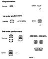
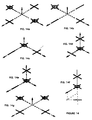
- Figure I shows the symbols employed herein for zero order, first order and second order gradiometer sensors, the symbols used to represent their outputs (s (0) , s (1) and s (2) respectively) and examples of some of the possible configurations of those sensors.
- the present invention is not limited to the use of sensors of any particular configuration and radial, planar or other sensor configurations may be employed as desired.
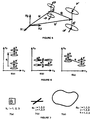
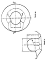
- Figure 2 shows a schematic representation of a zero order gradiometer sensor.
- the sensor is located at a position u relative to an origin and comprises a single coil of N turns.
- the sensor is defined by the characteristic unit vector p which is perpendicular to the coil area.
- the output s (0) of the sensor is the component of B perpendicular to the plane of the sensor coil (the dot product of B with p ) times the gain of the sensor and is given by equation 5 in Appendix A where ⁇ B is the gain of the sensor.
- the sensor output is given by the projection of the magnetic field vector into the direction of the sensor coil vector p .
- Each sensor coil is located at a position represented by position vectors u 1 , u 2 respectively and the two coils are separated by a gradiometer baseline represented by characteristic baseline vector d.
- the output of the sensor s (1) is given by the difference between the measurements from the two sensors, as shown in equation 6 in Appendix A, where ⁇ G is the gain of the sensor.
- equation 6 may be rewritten as shown in equation 7 in Appendix A.
- the output of the sensor is a projection of the first gradient tensor into the vectors p and d .
- Figures 4a through 4c show three of the many other possible configurations for first order gradiometers.
- the sensor output is a mixture of first order gradient components.
- FIG. 5 shows a schematic representation of a second order gradiometer.
- a second order gradiometer generally comprises four coils which are usually arranged to form two first order gradiometers.
- the characteristic baselines d,d' are parallel and the characteristic coil unit vectors p,p' are opposite.
- the output of the second order gradiometer is a projection of the second gradient tensor into the characteristic vectors p, q and d , where p is the coil orientation and q and d are the gradiometer baselines.
- the output is a mixture of second order gradient components.
- the present invention combines the measurements obtained from the sensors with measurements obtained from a reference system.
- the reference system may include a tensor magnetometer, a first order tensor gradiometer and/or a second order tensor gradiometer and/or higher order tensor gradiometers.
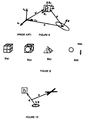
- Figure 7a shows the symbol used herein to represent a tensor magnetometer and the symbol used to represent its output
- Figure 7b shows the symbol used herein to represent a first gradient tensor and the symbol used to represent its output
- Figure 7c shows the symbol used herein to represent a second gradient tensor and the symbol used to represent its output.
- tensor gradiometer is intended to comprise a reference device which returns sufficient infomation to completely define the relevant measured characteristic, whether that be a zero order gradient (3 components of magnetic field), first order gradient (at least five linearly independent components), second order gradient (at least seven linearly independent components), etc.
- Figure 8 shows a prior art system wherein a tensor magnetometer has been combined with a magnetometer sensor to obtain measurements substantially equivalent to measurements which would be obtained with a first order gradiometer.
- This system projects the relevant components of the magnetic measurements from the reference system to p and combines them with the sensor measurements to obtain a measurement which is substantially equivalent to that which would have been obtained from a first order gradiometer.
- the present invention has advantages that it can provide measurements substantially equivalent to those which would be obtained from second, third or higher order gradiometers. Further, the present invention is not particularly limited in that it may employ sensor gradiometers of zero, first, second or higher orders, provided that the magnetic measurement is at least two orders higher than the order of the sensor gradiometers.
- the present invention employs a novel reference system which may comprise tensor gradiometers of zero, first, second or higher orders, provided that a sensor gradiometer for each higher order upto one order less than the selected order is provided.
- a novel reference system which may comprise tensor gradiometers of zero, first, second or higher orders, provided that a sensor gradiometer for each higher order upto one order less than the selected order is provided.
- Figure 9a shows one possible reference tensor magnetometer configuration wherein three mutually orthogonal sensor coils are wrapped around a cubical carrier.
- Figure 9b shows another possible configuration wherein the three mutually orthogonal sensor coils are placed on appropriate faces of a cubical carrier.
- Figure 9c shows a configuration, such as that disclosed in U.S. patent 5,311,129 to Ludwig et al., wherein each of the three sensor coils are placed on a respective one of three faces of a pyramid-shaped carrier and are thus non-orthogonal to each other.
- Figure 9d shows the general case wherein three sensor coils are distributed in space.
- the reference system of the present invention employs an orthogonal or a non-orthogonal configuration, it is important to note that it is not required that the sensor be aligned with any of the axes of the reference system.
- Equation 10 in Appendix A shows how the first order gradiometer output s (1) of the prior art system of Figure 8 is formed by projecting b i , which are the three orthgonalized components of the magnetic field measured by the reference tensor magnetometer, to p and combining these values with the measured zero order sensor output s (0) after the gains of the sensor ⁇ s and the reference system ⁇ B have been normalized.
- b i are the three orthgonalized components of the magnetic field measured by the reference tensor magnetometer
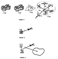
- Figure 10 shows a schematic representation of an embodiment of the present invention which is used to obtain a magnetic measurement from a magnetometer which is substantially equivalent to a measurement that would be obtained from a second order gradiometer.
- the system differs from that shown in Figure 8 in that the reference system comprises a tensor zero order gradiometer and a tensor first order gradiometer.
- the reference system first order tensor gradiometer can be constructed in a variety of manners, a few possible configurations of which are shown in Figures 11a through 11d.
- Figure 11a shows a first order tensor gradiometer configuration wherein the gradiometer coils are wrapped around appropriate portions of a cruciform-shaped carrier and this configuration, with circular coils, is presently preferred by the inventors.
- Figure 11b shows another first order tensor gradiometer configuration wherein the gradiometer coils are placed on appropriate faces of a cruciform-shaped carrier.
- Figure 11c shows a first order tensor gradiometer configuration as taught in the above-mentioned Ludwig patent.
- Figure 11d shows the general case of the tensor gradiometer coils distributed in space. Other configurations will also be apparent to those of skill in the art and may be preferred in some circumstances due to manufacturing or assembly concerns.
- the axis of the sensor correspond to any axis of the reference system.
- the axes of the reference system tensor magnetometer correspond to the axes of the reference system first order tensor gradiometer. It should be noted however, that signal complexity and the associated signal processing requirements are reduced if the reference system tensor magnetometer and first order tensor gradiometer are aligned (for example having three common axes).
- measurements obtained by the magnetometer (zero order gradiometer) sensor and measurements obtained by the reference tensor magnetometer are combined appropriately to obtain a first order gradiometer measurement which is then appropriately combined with measurements obtained by the reference system first order tensor gradiometer to obtain a measurement substantially equivalent to a measurement that would be obtained from a second order gradiometer sensor.
- this procedure is the projection of reference tensor magnetometer and reference tensor first order gradiometer outputs into the characteristic vectors of the sensor and reference system ( p,q,d ).
- the magnetometer (zero order gradiometer) sensor is characterized by vector p.
- the second order gradiometer measurement is obtained from equation 12 in Appendix A, where ⁇ s and ⁇ B are defined as before, ⁇ G1 is the gain of the reference first order tensor gradiometer, d is the baseline of the equivalent first order gradiometer formed from the sensor magnetometer and the reference magnetometer outputs and d G1 is the baseline of the reference first order tensor gradiometers which, in this example, is assumed to be equal for all components. In this particular example, for clarity and simplicity of description, it has been assumed that the gains of each component are the same in the tensor magnetometer and the first order tensor gradiometer and also that the baselines of the first order tensor gradiometer are the same. It will be apparent to those of skill in the art that this need not be the case and that equation 12 may easily be rewritten to accommodate variable gains or baselines.
- equation 12 may be rewritten to express the second order gradiometer output as a linear combination of the reference outputs as shown in equation 14 of Appendix A.
- the coefficients c are defined as before.
- ⁇ s is the gain of the sensor
- ⁇ Gij is the gain of the reference first gradient tensor component ij
- d ij is the baseline length of the reference tensor first order gradiometer
- p (p 1 , p 2 , p 3 ) is the characteristic coil vector of the sensor.
- Second order gradient measurement from first order gradiometer sensor
- Figure 12 shows a schematic representation of a system for comparison with the present invention, which is used to obtain a magnetic measurement from a first order gradiometer which is substantially equivalent to a measurement that would be obtained from a second order gradiometer.
- the output of the sensor, s (1) is given by equation 7 and the desired second gradient measurement s (2) is again obtained by projecting the reference first order gradient tensor into the characteristic vectors p and d, as in the third term of equation 12 and the result is combined with the sensor output s (1) .
- the second gradient s (2) may be expressed as a linear combination of the reference first order gradient tensor outputs as in equation 20 in Appendix A and wherein the coefficients k are those given in equations 15 through 19. It will be apparent that, in equations 15 through 19, provisions have been made for varied gains and/or baselines.
- Figure 13 shows a schematic representation of an embodiment of the present invention which is used to obtain a magnetic measurement from a zero order gradiometer which is substantially equivalent to a measurement that would be obtained from a third order gradiometer.
- the system differs from that shown in Figure 12 in the addition of a second order tensor gradiometer to the reference system.
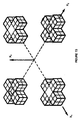
- the reference second order tensor gradiometer can be constructed in a variety of manners, some of which are shown in Figures 14a through 14g. Other configurations will also be apparent to those of skill in the art and may be preferred in some circumstances due to manufacturing or assembly concerns. It will be observed that the configurations of the reference system second order tensor gradiometers shown in Figures 14a and 14g include redundant components. These redundant components are included to provide fault tolerance to cope with a failure of a component in the reference system.
- the bars (non-cruciforms) in Figure 14 represent incomplete tensor gradiometers with components as required by a particular configuration of the reference tensor gradiometer.
- the required first order tensor gradient components are obtained either from the direct measurements or are synthesized from strategically located zero order sensors and the zero order components are obtained from the tensor magnetometer included in this configuration.
- the sensor magnetometer zero order gradiometer
- the sensor is a magnetometer specified by characteristic vector p and gain ⁇ s .
- equation 21 in Appendix A may be derived for the third order gradient measurement.
- ⁇ B , ⁇ G1 and ⁇ G2 are the gains of the reference system tensor magnetometer, first order tensor gradiometer and second order tensor gradiometer respectively.
- g (1) corresponds to the first order tensor gradiometer outputs
- g (2) corresponds to the second order tensor gradiometer outputs.
- the third gradient s (3) may be expressed as a linear combination of the reference second order gradient tensor outputs, reference first order gradient tensor outputs and reference tensor magnetometer outputs.
- the third order gradiometer output can then be formed from equation 22 in Appendix A where all parameters are as described before.
- the reference second order tensor gradiometer comprises a number of first order gradiometers which are organized in groups which measure first order gradient tensors.
- the last term of equation 22 may be re-written as a simpler combination of these first order gradiometer terms.
- the reference second order tensor gradiometer consists of two first order tensor gradiometers and two partially populated first order tensor gradiometers. If the outputs of these tensor gradiometers are denoted by v, x, y and z, it will be apparent to those of skill in the art that each of v and x has two linearly independent components while each of y and z have five linearly independent components.
- the reference tensor magnetometer may be located either spaced from or at the same location as the first order tensor gradiometer.
- the reference tensor magnetometer may be spaced from or at the same location as some elements of the reference second order tensor gradiometer.
- the reference first order gradiometer may be spaced from or at the same location of some elements of the reference second order gradiometer.
- the reference tensor magnetometer is located at element G which is the reference first order gradiometer.
- element G forms one part of the reference second order gradiometer.
- the redundant elements allow the reference second order gradiometer and/or the reference first order gradiometer to be reconfigured (i.e. - constructed from a different selected set of elements) as required.
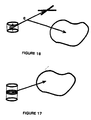
- Figure 16 shows a schematic representation of an embodiment of the present invention which is used to obtain a magnetic measurement from a first order gradiometer which is substantially equivalent to the measurement that would be obtained from a third order gradiometer.
- the third order gradiometer measurement may be obtained in a manner similar to equation 21, where the second term on the right hand side of the equal sign is omitted.
- the third gradient measurement may be expressed as a linear combination of reference system outputs in a manner similar to equation 23 with the second term omitted, resulting in equation 24 in Appendix A wherein all of the parameters are defined as before.
- the sensor, the first order tensor gradiometer or the second order tensor gradiometer be aligned, nor be located at any particular location relative to each other.
- figure 17 shows a schematic representation of a system with which is used to obtain a magnetic measurement from a second order gradiometer which is substantially equivalent to the measurement which would be obtained from a third order gradiometer.
- the second order gradiometer sensor is specified by the characteristic vectors p, q and d.
- the third order gradiometer measurement is obtained in a similar manner to that discussed above and results in equation 25 in Appendix A wherein all of the parameters are defined as before.
- the present invention provides a method and system to obtain magnetic measurements with a sensor of a predefined order and to combine those measurements with measurements from a reference system to obtain measurements substantially equivalent to those which would be obtained from a sensor of a higher order.
- the reference system provides tensor information for each of the orders from the predefined sensor order to one order less than that of the desired order of the measurement.
- the reference system would include a tensor magnetometer, a first order tensor gradiometer and a second order tensor gradiometer.
- the reference system need only include a first order tensor gradiometer and a second order tensor gradiometer, although for many systems it may be necessary to include a tensor magnetometer for other purposes.
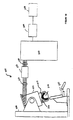
- Figure 18 shows an embodiment of the present invention comprising a 143 channel biomagnetometer system 200.
- System 200 comprises a dewar 204 which is supported by a gantry 208, the dewar having a head-shaped helmet 216 at is lower end, and a patient support 220 which supports a patient while the patient's head is inserted into helmet 216.
- Dewar 204 includes an array 212 of gradiometer sensors about helmet 216 and a reference system 224 above helmet 216.
- the SQUIDs associated with array 212 of sensors and reference system 224 are located above reference system 224 within dewar 204 which is filled with a cryogen (for example liquid helium for low temperature superconductor or liquid nitrogen for high temperature superconductors) in operation.
- a cryogen for example liquid helium for low temperature superconductor or liquid nitrogen for high temperature superconductors
- gantry 208 is designed to minimize vibrations and to have a relatively high characteristic frequency.
- gantry 208 will be designed with different characteristics for different biomagnetic sources, for example cardiac measurements. The design of such a gantry is not particularly limited and various techniques and design will occur to those of skill in the art.
- the outputs 228 of the sensors and the reference system are amplified to a desired level by SQUID pre-amplifiers 232 and the resulting signals 236 are processed by System Electronics 240.
- System Electronics 240 comprises a plurality of SQUID controllers and analog to digital (A/D) conversion means, to convert signals 236 to digital values, and a plurality of digital signal processors (DSPs) to perform desired processing of these digital values.
- DSPs digital signal processors
- Texas Instruments TMS320 DSP processors are employed to process these digital values.
- each DSP processes signals from up to eight sensors of array 212 of sensors and this provides sufficient processing speed to allow real time processing of these signals.
- the resulting signals are forwarded to an Acquisition computer 244 and a Processing computer 248 via a suitable communications link, such as a SCSI interface.
- Acquisition computer 244 and Processing computer 248 are different computer systems, but in some circumstances they may be combined in a single computer system.
- Acquisition computer 244 and Processing computer 248 can be any suitable computer systems with graphical workstation capabilities such as, for example, a suitably equipped Unix-based workstation or a member of the Macintosh family of microcomputers manufactured by Apple. Acquisition computer 244 performs several tasks, including tuning of SQUIDS, data collection and storage and control of optional peripheral components, such as stimulus and EEG systems. Processing computer 248 performs off-line data processing of stored data and display of real time or stored data. As will be apparent to those of skill in the art, processing computer 248 may also combine data from the biomagnetometer with other data, such as MRI or CAT scans, to produce graphical displays which can be interpreted in a more intuitive manner.
- processing computer 248 may also combine data from the biomagnetometer with other data, such as MRI or CAT scans, to produce graphical displays which can be interpreted in a more intuitive manner.
- EEG or other data of interest may be collected simultaneously with the measurements made by array of sensors 212 and reference system 224 and, in the preferred embodiment, system electronics 240 includes 64 channels to which such inputs may be applied.
- the array 212 of sensors is composed of first order gradiometer sensors.
- One of the advantages of the present invention is that by combining the reference system with a plurality of sensors, the effective order of those sensors can be increased to a second, third or higher order (provided that the reference system includes a tensor gradiometer for each order from the sensor order to one order less than the desired measurement order) merely by appropriately combining and processing the sensor and reference system signals.
- the effective order of the measured signals may be changed as desired to observe differences in the signals. This change may be accomplished "on the fly" to signals being processed in real time or may be applied off-line to signals previously obtained and stored.
- Another advantage of the present invention is that systems such as the one shown in Figure 18, may employ first order gradiometer sensors when installed in a moderately magnetically shielded room and, by processing the signals as disclosed herein, obtain results which would otherwise require a heavily magnetically shielded room. Thus, the costs associated with the shielding of a site for such systems is reduced. If the system is used in an environment subject to less magnetic noise, such as a heavily shielded room, the system may employ magnetometer sensors, if desired.
- FIG 19 shows helmet 216, array 212 of sensors, reference system 224 and a portion of dewar 204 in more detail.
- helmet 216 is formed of two spaced and generally parallel walls 249,250 which define a vacuum space therebetween.
- Each of sensor gradiometers 252, which make up array 212 of sensors, is mounted to wall 250 of helmet 216 and wall 249 is shaped to receive a human head.
- Helmet 216 is shaped such that each sensor 252 is located in close proximity to the surface of the human head received therein.
- helmets can be constructed, along anthropometric lines, for biomagnetometer systems intended for use with different races.
- Figures 20 and 21 show a helmet in accordance with the present invention.
- dimension F indicates the helmet front to back depth
- dimension G indicates the helmet height
- dimension H indicates the helmet width.
- ear channels 300 are also provided to accomodate ears while providing a closer fit about the rest of the skull.
- One preferred shape has been found to be an F dimension of about 230mm, a G dimension of about 220mm and an H dimension of about 190mm.
- the present inventors have constructed a helmet based on anthropometric information provided by Dr. D. Racansky of the University of Toronto Institute of Biomedical Engineering for use on occidentals and has an F dimension of about 213mm, a G dimension of about 186mm and an H dimension of about 161 mm.
- a helmet 216 for use on orientals.
- This helmet has an F dimension of about 203 mm, a G dimension of about 178 mm and an H dimension of about 172 mm.
- F dimension of about 203 mm
- G dimension of about 178 mm
- H dimension of about 172 mm.
- other sizes and/or modified shapes will also occur to those of skill in the art and are not intended to be excluded from these discussions.
- helmet 216 is tilted at an angle of 15 degrees with respect to the axis of dewar 204. Specifically, helmet 216 is tilted raising the front portion of the helmet and lowering the back portion and this results in an improved 'fit' between the helmet and the subject's head.
- the present invention provides a novel method and system for obtaining higher order gradiometer measurements with lower order gradiometers. This is accomplished by appropriately combining measurements obtained from sensor gradiometers of a given order with measurements obtained from a reference system which includes a tensor gradiometer for each order from the sensor order to one order less than the desired order.
- the present invention allows the desired order to be changed, either on real time, on-line data or on stored, off-line data.
Landscapes
- Physics & Mathematics (AREA)
- Condensed Matter Physics & Semiconductors (AREA)
- General Physics & Mathematics (AREA)
- Measurement And Recording Of Electrical Phenomena And Electrical Characteristics Of The Living Body (AREA)
- Measuring Magnetic Variables (AREA)
Claims (26)
- Verfahren zur Erhaltung einer magnetischen Messung, die im Wesentlichen dem gleichwertig ist, was von einem Gradiometer einer gewählten Ordnung, die gleich der zweiten oder höherer Ordnung ist, erhalten werden würde, wobei die magnetische Messung um mindestens zwei Ordnungen höher als eine vorhandene bestimmte Ordnung des wenigstens einen Mess-Gradiometers ist, das vom Messsystem (200) verwendet wird, die Schritte umfassend:(i) Anordnen des Mess-Gradiometers in einer ersten Stellung,(ii) Anordnen eines Referenzsystems (224), das von der ersten Stellung beabstandet ist, wobei das Referenzsystem (224) mindestens ein Tensor-Gradiometer (B) der vorhandenen Ordnung umfasst und ein Signal, das für ein Tensor-Gradiometer charakteristisch ist, für jede höhere Ordnung bis zu einer Ordnung weniger als die ausgewählte Ordnung bereitstellt, sodass ein Tensor für jede der Ordnungen von dem Referenzsystem (200) ermittelt werden kann,(iii) Ermitteln des Tensors jeder Ordnung des Referenzsystems (224),(iv) Ermitteln eines Satzes von charakteristischen Vektoren (p, q, d) des Mess-Gradiometers bezüglich des Referenzsystems (224),(v) Messen des Ausgangs des Mess-Gradiometers,(vi) Projizieren jedes ermittelten Tensors des Referenzsystems (224) auf den Satz charakteristischer Vektoren (p, q, d) des Mess-Gradiometers und Kombinieren des Ergebnisses der Projektion mit dem gemessenen Ausgang (228), um die magnetische Messung zu bilden, die im wesentlichen dem gleichwertig ist, was von dem Messgerät der ausgewählten Ordnung erhalten werden würde.
- Verfahren gemäß Anspruch 1, das enthält, die Schritte (iii) bis (vi) für jedes einer Vielzahl von Mess-Gradiometern der vorhandenen Ordnung zu wiederholen.
- Verfahren gemäß Anspruch 2, wobei die vorhandene Ordnung die nullte Ordnung ist.
- Verfahren gemäß Anspruch 2, wobei die vorhandene Ordnung die erste Ordnung ist.
- Verfahren gemäß Anspruch 2, wobei die vorhandenen Ordnung die zweite Ordnung ist.
- Verfahren gemäß Anspruch 2, wobei Schritt (vi) ausgeführt wird, indem ein Satz von linear unabhängigen Komponenten (g) jedes ermittelten Tensors des Referenzsystems (224) auf den Satz der charakteristischen Vektoren (p, q, d) jedes einer Vielzahl von Mess-Gradiometern projiziert wird und indem die Ergebnisse der Projektion mit den gemessenen Ausgängen (228) durch lineare Operationen kombiniert werden.
- Verfahren nach Anspruch 6, wobei jeder Satz von linear unabhängigen Komponenten (g) jedes ermittelten Tensors ein minimaler Satz der Komponenten (g) ist.
- System (200) zur Erhaltung magnetischer Messungen, die im Wesentlichen dem gleichwertig sind, was von einem Gradiometer einer ausgewählten Ordnung erhalten werden würde, die gleich der zweiten oder höheren Ordnung ist, und um mindestens zwei Ordnungen höher ist als eine bestimmte Ordnung des mindestens einen Mess-Gradiometers, das vom System (200) verwendet wird, umfassend:(i) mindestens ein Mess-Gradiometer der bestimmten Ordnung, das einen gemessenen Ausgang erzeugt,(ii) ein Referenzsystem (224) das von dem zumindest einen Mess-Gradiometer beabstandet ist, wobei das Referenzsystem (224) mindestens ein Tensor-Gradiometer (B) der bestimmten Ordnung umfasst und ein Signal, das für ein Tensor-Gradiometer charakteristisch ist, für jede höhere Ordnung bis zu einer Ordnung weniger als die ausgewählte Ordnung bereitstellt, sodass ein Tensor für jede der Ordnungen von dem Referenzsystem (200) ermittelt werden kann,(iii) eine Signalverarbeitungseinrichtung (246) zum Ermitteln eines Satzes charakteristischer Vektoren (p, q, d) von dem mindestens einem Mess-Gradiometer bezüglich des Referenzsystems (200), wobei die Signalverarbeitungseinrichtung (240) einen Ausgang (228) jedes der Tensor-Gradiometer (B) des Referenzsystems (224) auf den Satz charakteristischer Vektoren des mindestens einen Mess-Gradiometers projiziert und das Ergebnis der Projektion mit dem gemessenen Ausgang (228) kombiniert, um die magnetische Messung zu bilden, die im Wesentlichen dem gleichwertig ist, was von dem Sensor der gewählten Ordnung erhalten werden würde.
- System gemäß Anspruch 8, das eine Vielzahl von Mess-Gradiometern umfasst.
- System gemäß Anspruch 9, wobei die vorhandene Ordnung der Vielzahl von Mess-Gradiometern die nullte Ordnung ist.
- System gemäß Anspruch 9, wobei die vorhandene Ordnung der Vielzahl von Mess-Gradiometern die erste Ordnung ist.
- System gemäß Anspruch 9, wobei die vorhandene Ordnung der Vielzahl von Mess-Gradiometern die zweite Ordnung ist.
- System gemäß Anspruch 8 zur Erhaltung von biomagnetischen Messungen, das eine Vielzahl von Mess-Gradiometern der bestimmten Ordnung umfasst.
- System (200) gemäß Anspruch 13, das zudem einen Helm (216) umfasst, um welchen die Vielzahl von Mess-Gradiometern (252) in Form eines Arrays (212) angeordnet ist, wobei der Helm (216) geformt ist, um einen menschlichen Kopf aufzunehmen.
- System (200) gemäß Anspruch 14, wobei der Helm (216) ein Volumen umfasst, dass von Ausmaßen einschließlich einer Tiefe von vorne bis hinten von ungefähr 230 mm, einer Höhe von ungefähr 220 mm und einer Weite von ungefähr 190 mm definiert ist.
- System (200) gemäß Anspruch 14, wobei der Helm (216) als ein Ende eines Dewar-Gefäßes (204) gebildet ist, das die Vielzahl von Mess-Gradiometern (252) und das Referenzsystem (224) umfasst, wobei das Dewar-Gefäß (204) bei Benutzung ein Kühlmittel enthält.
- System (200) gemäß Anspruch 16, wobei das Dewar-Gefäß (204) von einem Gestell (208) getragen ist.
- System (200) gemäß Anspruch 13, wobei die genannte Verarbeitungseinrichtung (240) eine Vielzahl von Signalverarbeitungsgeräten umfasst, wobei jedes der Vielzahl von Signalverarbeitungsgeräten Signale von mehr als einem der Mess-Gradiometer (252) verarbeitet.
- System (200) gemäß Anspruch 13, das zudem EEG-Eingangsmittel (240) umfasst.
- System (200) gemäß Anspruch 13, wobei die digitalisierten Messsignale zum rechnerunabhängigen Verarbeiten gespeichert werden.
- System gemäß Anspruch 20, wobei die gewählte Ordnung ausgewählt wird, nachdem die digitalisierten Messsignale gespeichert werden.
- System gemäß Anspruch 19, wobei die EEG-Eingangsmittel (240) gleichzeitig von der Vielzahl von Mess-Gradiometern und von den Tensor-Gradiometern (B) aufgenommene EEG-Messungen sammeln.
- Verfahren gemäß Anspruch 6, wobei Schritt (iii) ausgeführt wird, indem der Satz linear unabhängiger Komponenten (g) jedes ermittelten Tensors des Referenzsystems (200) ermittelt wird.
- System gemäß Anspruch 9, wobei das Referenzsystem (224) den ermittelten Tensor mindestens zwei der Vielzahl von Mess-Gradiometern zur Verfügung stellt.
- Verfahren gemäß Anspruch 1, wobei das Mess-Gradiometer in einer willkürlichen räumlichen Anordnung bezüglich einer Komponente des Referenzsystems (224) angeordnet ist.
- System gemäß Anspruch 8, wobei das mindestens eine Mess-Gradiometer in einer willkürlichen räumlichen Anordnung bezüglich einer Komponente des Referenzsystems (228) angeordnet ist.
Applications Claiming Priority (3)
| Application Number | Priority Date | Filing Date | Title |
|---|---|---|---|
| US476290 | 1995-06-07 | ||
| US08/476,290 US5657756A (en) | 1995-06-07 | 1995-06-07 | Method and systems for obtaining higher order gradiometer measurements with lower order gradiometers |
| PCT/CA1996/000393 WO1996041209A1 (en) | 1995-06-07 | 1996-06-07 | Method and system for obtaining higher order gradiometer measurements with lower order gradiometer |
Publications (2)
| Publication Number | Publication Date |
|---|---|
| EP0830612A1 EP0830612A1 (de) | 1998-03-25 |
| EP0830612B1 true EP0830612B1 (de) | 2004-05-26 |
Family
ID=23891258
Family Applications (1)
| Application Number | Title | Priority Date | Filing Date |
|---|---|---|---|
| EP96918537A Expired - Lifetime EP0830612B1 (de) | 1995-06-07 | 1996-06-07 | Verfahren und anordnung zur erhaltung von hoheren-ordnung-gradiometermessungen mit gradiometer von niedriger ordnung |
Country Status (7)
| Country | Link |
|---|---|
| US (1) | US5657756A (de) |
| EP (1) | EP0830612B1 (de) |
| JP (1) | JPH11506198A (de) |
| AU (1) | AU6117296A (de) |
| CA (1) | CA2223748C (de) |
| DE (1) | DE69632583T2 (de) |
| WO (1) | WO1996041209A1 (de) |
Families Citing this family (51)
| Publication number | Priority date | Publication date | Assignee | Title |
|---|---|---|---|---|
| US7092352B2 (en) * | 1993-07-23 | 2006-08-15 | Aquity, Llc | Cancellation systems for multicarrier transceiver arrays |
| JP3194695B2 (ja) * | 1995-12-14 | 2001-07-30 | 学校法人金沢工業大学 | 磁気計測装置、その組立方法及び修理方法、並びに磁気計測用診断装置 |
| JP3237590B2 (ja) * | 1997-10-24 | 2001-12-10 | 株式会社日立製作所 | 磁場計測装置 |
| US6842637B2 (en) * | 1997-10-24 | 2005-01-11 | Hitachi, Ltd. | Magnetic field measurement apparatus |
| US6370414B1 (en) | 1998-01-23 | 2002-04-09 | Ctf Systems, Inc. | System and method for measuring, estimating and displaying RMS current density maps |
| FI112399B (fi) | 1998-08-28 | 2003-11-28 | Neuromag Oy | Menetelmä ja laite taustahäiriön poistamiseksi monikanavaisista ilmaisinasetelmista |
| US6267953B1 (en) * | 1999-05-04 | 2001-07-31 | The United States Of America As Represented By The Secretary Of Agriculture | Chemical composition that attract arthropods |
| JP3379488B2 (ja) * | 1999-09-14 | 2003-02-24 | 株式会社日立製作所 | 磁場計測装置 |
| US7462366B2 (en) | 2002-03-29 | 2008-12-09 | Boston Scientific Scimed, Inc. | Drug delivery particle |
| US7094369B2 (en) | 2002-03-29 | 2006-08-22 | Scimed Life Systems, Inc. | Processes for manufacturing polymeric microspheres |
| US7131997B2 (en) | 2002-03-29 | 2006-11-07 | Scimed Life Systems, Inc. | Tissue treatment |
| US7053134B2 (en) | 2002-04-04 | 2006-05-30 | Scimed Life Systems, Inc. | Forming a chemically cross-linked particle of a desired shape and diameter |
| WO2003088839A2 (en) * | 2002-04-17 | 2003-10-30 | Board Of Trustees Of The University Of Arkansas | Uterine magnetomyography |
| CA2492339A1 (en) | 2002-06-12 | 2003-12-24 | Boston Scientific Limited | Bulking agents |
| US7449236B2 (en) | 2002-08-09 | 2008-11-11 | Boston Scientific Scimed, Inc. | Porous polymeric particle comprising polyvinyl alcohol and having interior to surface porosity-gradient |
| US7842377B2 (en) | 2003-08-08 | 2010-11-30 | Boston Scientific Scimed, Inc. | Porous polymeric particle comprising polyvinyl alcohol and having interior to surface porosity-gradient |
| US8012454B2 (en) | 2002-08-30 | 2011-09-06 | Boston Scientific Scimed, Inc. | Embolization |
| US7883490B2 (en) | 2002-10-23 | 2011-02-08 | Boston Scientific Scimed, Inc. | Mixing and delivery of therapeutic compositions |
| US7588825B2 (en) | 2002-10-23 | 2009-09-15 | Boston Scientific Scimed, Inc. | Embolic compositions |
| FI115324B (fi) | 2003-03-14 | 2005-04-15 | Elekta Neuromag Oy | Menetelmä ja järjestelmä monikanavaisen mittaussignaalin käsittelemiseksi |
| US7976823B2 (en) | 2003-08-29 | 2011-07-12 | Boston Scientific Scimed, Inc. | Ferromagnetic particles and methods |
| US7736671B2 (en) | 2004-03-02 | 2010-06-15 | Boston Scientific Scimed, Inc. | Embolization |
| US8173176B2 (en) | 2004-03-30 | 2012-05-08 | Boston Scientific Scimed, Inc. | Embolization |
| US7311861B2 (en) | 2004-06-01 | 2007-12-25 | Boston Scientific Scimed, Inc. | Embolization |
| US8425550B2 (en) | 2004-12-01 | 2013-04-23 | Boston Scientific Scimed, Inc. | Embolic coils |
| US7727555B2 (en) | 2005-03-02 | 2010-06-01 | Boston Scientific Scimed, Inc. | Particles |
| US7858183B2 (en) | 2005-03-02 | 2010-12-28 | Boston Scientific Scimed, Inc. | Particles |
| US7963287B2 (en) | 2005-04-28 | 2011-06-21 | Boston Scientific Scimed, Inc. | Tissue-treatment methods |
| GB2425610A (en) * | 2005-04-29 | 2006-11-01 | Univ London | Magnetic properties sensing system |
| US9463426B2 (en) | 2005-06-24 | 2016-10-11 | Boston Scientific Scimed, Inc. | Methods and systems for coating particles |
| US8007509B2 (en) | 2005-10-12 | 2011-08-30 | Boston Scientific Scimed, Inc. | Coil assemblies, components and methods |
| US8101197B2 (en) | 2005-12-19 | 2012-01-24 | Stryker Corporation | Forming coils |
| US8152839B2 (en) | 2005-12-19 | 2012-04-10 | Boston Scientific Scimed, Inc. | Embolic coils |
| US7947368B2 (en) | 2005-12-21 | 2011-05-24 | Boston Scientific Scimed, Inc. | Block copolymer particles |
| US7501179B2 (en) | 2005-12-21 | 2009-03-10 | Boston Scientific Scimed, Inc. | Block copolymer particles |
| US8414927B2 (en) | 2006-11-03 | 2013-04-09 | Boston Scientific Scimed, Inc. | Cross-linked polymer particles |
| JP2010187708A (ja) * | 2008-01-10 | 2010-09-02 | Univ Of Tokushima | 顎運動の測定装置とこれに使用されるセンサコイルの製造方法 |
| GB0900906D0 (en) * | 2009-01-20 | 2009-03-04 | Schlieffers Jorg | Removing or reducing the airwave in CSEM data by using weighted field differences |
| US8593141B1 (en) | 2009-11-24 | 2013-11-26 | Hypres, Inc. | Magnetic resonance system and method employing a digital squid |
| US10634741B2 (en) * | 2009-12-04 | 2020-04-28 | Endomagnetics Ltd. | Magnetic probe apparatus |
| US9427186B2 (en) * | 2009-12-04 | 2016-08-30 | Endomagnetics Ltd. | Magnetic probe apparatus |
| US8970217B1 (en) | 2010-04-14 | 2015-03-03 | Hypres, Inc. | System and method for noise reduction in magnetic resonance imaging |
| US20120001638A1 (en) | 2010-06-30 | 2012-01-05 | Hall David R | Assembly and Method for Identifying a Ferrous Material |
| WO2012068493A1 (en) | 2010-11-18 | 2012-05-24 | Johns Hopkins University | Magnetoencephalography system and method for 3d localization and tracking of electrical activity in brain |
| CN105283202B (zh) | 2013-03-11 | 2019-04-23 | 安都磁学有限公司 | 用于淋巴结检测的低渗溶液 |
| US9234877B2 (en) | 2013-03-13 | 2016-01-12 | Endomagnetics Ltd. | Magnetic detector |
| US9239314B2 (en) | 2013-03-13 | 2016-01-19 | Endomagnetics Ltd. | Magnetic detector |
| US9671214B2 (en) | 2013-07-17 | 2017-06-06 | Infineon Technologies Ag | Discrete magnetic angle sensor device, a magnetic angle sensor arrangement, a method for generating an angle signal and a method for providing a sensor signal |
| US9245547B1 (en) * | 2015-02-19 | 2016-01-26 | Allegro Microsystems, Llc | Magnetic sensor having enhanced linearization |
| EP3782575A1 (de) | 2015-06-04 | 2021-02-24 | Endomagnetics Ltd. | Markermaterialien und -formen zur lokalisierung magnetischer marker |
| CN111580023B (zh) * | 2020-06-24 | 2024-10-18 | 自然资源部第一海洋研究所 | 全轴磁力梯度仪、磁力作业系统及作业方法 |
Family Cites Families (13)
| Publication number | Priority date | Publication date | Assignee | Title |
|---|---|---|---|---|
| DE3247585A1 (de) * | 1982-12-22 | 1984-06-28 | Siemens AG, 1000 Berlin und 8000 München | Mehrkanalige vorrichtung zur messung von verschiedenen feldquellen hervorgerufener schwacher magnetfelder |
| US5026682A (en) * | 1987-04-13 | 1991-06-25 | International Business Machines Corporation | Devices using high Tc superconductors |
| DE3886044D1 (de) * | 1988-09-23 | 1994-01-13 | Siemens Ag | Einrichtung und Verfahren zur Messung von schwachen, orts- und zeitabhängigen Magnetfeldern. |
| US5311129A (en) * | 1990-02-02 | 1994-05-10 | Dornier Gmbh | Local magnetic field measurement apparatus having gradiometers arranged on non-parallel, non-orthogonal surfaces |
| DE4005079A1 (de) * | 1990-02-17 | 1991-08-22 | Dornier Gmbh | Vorrichtung zur vollstaendigen bestimmung des gradiententensors eines magnetfelds |
| US5122744A (en) * | 1990-10-09 | 1992-06-16 | Ibm Corporation | Gradiometer having a magnetometer which cancels background magnetic field from other magnetometers |
| GB2258314B (en) * | 1991-08-02 | 1995-07-19 | Dornier Gmbh | Device for measuring local magnetic field distributions |
| JPH0542119A (ja) * | 1991-08-12 | 1993-02-23 | Fujitsu Ltd | 生体磁気計測装置 |
| US5187436A (en) * | 1992-03-13 | 1993-02-16 | General Electric Company | Noise cancellation method in a biomagnetic measurement system using an extrapolated reference measurement |
| JP3204542B2 (ja) * | 1992-07-24 | 2001-09-04 | 株式会社東芝 | 磁場源測定装置 |
| FI98337C (fi) * | 1992-11-30 | 1997-06-10 | Risto Juhani Ilmoniemi | Menetelmä ja laite aivojen herätevasteiden ja spontaanitoiminnan sekä sydämestä mitattujen signaalien eri komponenttien erottelemiseksi toisistaan |
| US5617856A (en) * | 1993-09-24 | 1997-04-08 | Osaka Gas Company Limited | Biological information-measuring apparatus |
| US5471985A (en) * | 1994-08-01 | 1995-12-05 | Biomagnetic Technologies, Inc. | Biomagnetometer with whole head coverage of a seated or reclined subject |
-
1995
- 1995-06-07 US US08/476,290 patent/US5657756A/en not_active Expired - Lifetime
-
1996
- 1996-06-07 WO PCT/CA1996/000393 patent/WO1996041209A1/en not_active Ceased
- 1996-06-07 CA CA002223748A patent/CA2223748C/en not_active Expired - Fee Related
- 1996-06-07 AU AU61172/96A patent/AU6117296A/en not_active Abandoned
- 1996-06-07 EP EP96918537A patent/EP0830612B1/de not_active Expired - Lifetime
- 1996-06-07 DE DE69632583T patent/DE69632583T2/de not_active Expired - Lifetime
- 1996-06-07 JP JP9500054A patent/JPH11506198A/ja not_active Ceased
Non-Patent Citations (1)
| Title |
|---|
| BECKER W. ET AL: "First experiences with a multichannel software gradiometer recording normal and tangential components of MEG", PHYSIOL. MEAS., vol. 14, 1993, pages A45 - A50 * |
Also Published As
| Publication number | Publication date |
|---|---|
| AU6117296A (en) | 1996-12-30 |
| CA2223748C (en) | 2002-09-24 |
| EP0830612A1 (de) | 1998-03-25 |
| JPH11506198A (ja) | 1999-06-02 |
| US5657756A (en) | 1997-08-19 |
| WO1996041209A1 (en) | 1996-12-19 |
| CA2223748A1 (en) | 1996-12-19 |
| DE69632583T2 (de) | 2005-06-09 |
| DE69632583D1 (de) | 2004-07-01 |
Similar Documents
| Publication | Publication Date | Title |
|---|---|---|
| EP0830612B1 (de) | Verfahren und anordnung zur erhaltung von hoheren-ordnung-gradiometermessungen mit gradiometer von niedriger ordnung | |
| Hämäläinen et al. | Interpreting magnetic fields of the brain: minimum norm estimates | |
| US4913152A (en) | Magnetoencephalograph (MEG) using a multi-axis magnetic gradiometer for localization and tracking of neuromagnetic signals | |
| US5526811A (en) | Apparatus and process for determining the sources of biomagnetic activity | |
| US6339328B1 (en) | Magnetic gradiometer incorporating global feedback | |
| Taulu et al. | Presentation of electromagnetic multichannel data: the signal space separation method | |
| Sulai et al. | Characterizing atomic magnetic gradiometers for fetal magnetocardiography | |
| JP3642061B2 (ja) | 磁場計測装置 | |
| EP2591375B1 (de) | Verfahren zur einstellung eines interferenzsignalraums in bio-magnetfeld-messungen | |
| CN104422915B (zh) | 用匀场线圈用于磁共振系统的患者适应的b0均匀化方法 | |
| Vrba | Multichannel SQUID biomagnetic systems | |
| US7061242B2 (en) | Magnetic resonance imaging system | |
| US5327088A (en) | Multiplexed echo trains in nuclear magnetic resonance | |
| EP0527482B1 (de) | Verfahren und Gerät zur Bestimmung der Biostromverteilung im Körper | |
| US12082915B2 (en) | Magnetic field measurement device, magnetic field measurement method, and recording medium having magnetic field measurement program recorded thereon | |
| US8473028B2 (en) | K-space sample density compensation for magnetic resonance image reconstruction | |
| KR20190005891A (ko) | 생체 자기장을 측정하는 장치 | |
| EP1052522A2 (de) | Verfahren und System zur Erzeugung einer maximalen Intensitätsprojektion eines nicht-ebenen Bildes | |
| JPH031839A (ja) | 脳磁計測装置 | |
| JP2000287949A (ja) | 磁気共鳴イメージング装置 | |
| JP4218128B2 (ja) | 磁気遮蔽装置 | |
| JP7060867B2 (ja) | 生体磁気計測装置及び生体磁気計測システム | |
| Rijpma et al. | Adaptive periodic distrubance cancellation in a set-up of two cryocoolers | |
| JP3227958B2 (ja) | 生体活動電流源推定方法 | |
| JPH05220124A (ja) | 生体磁気計測装置 |
Legal Events
| Date | Code | Title | Description |
|---|---|---|---|
| PUAI | Public reference made under article 153(3) epc to a published international application that has entered the european phase |
Free format text: ORIGINAL CODE: 0009012 |
|
| 17P | Request for examination filed |
Effective date: 19980106 |
|
| AK | Designated contracting states |
Kind code of ref document: A1 Designated state(s): DE FI FR GB IT NL |
|
| 17Q | First examination report despatched |
Effective date: 19991126 |
|
| GRAH | Despatch of communication of intention to grant a patent |
Free format text: ORIGINAL CODE: EPIDOS IGRA |
|
| GRAS | Grant fee paid |
Free format text: ORIGINAL CODE: EPIDOSNIGR3 |
|
| GRAA | (expected) grant |
Free format text: ORIGINAL CODE: 0009210 |
|
| AK | Designated contracting states |
Kind code of ref document: B1 Designated state(s): DE FI FR GB IT NL |
|
| PG25 | Lapsed in a contracting state [announced via postgrant information from national office to epo] |
Ref country code: NL Free format text: LAPSE BECAUSE OF FAILURE TO SUBMIT A TRANSLATION OF THE DESCRIPTION OR TO PAY THE FEE WITHIN THE PRESCRIBED TIME-LIMIT Effective date: 20040526 Ref country code: FI Free format text: LAPSE BECAUSE OF FAILURE TO SUBMIT A TRANSLATION OF THE DESCRIPTION OR TO PAY THE FEE WITHIN THE PRESCRIBED TIME-LIMIT Effective date: 20040526 |
|
| REG | Reference to a national code |
Ref country code: GB Ref legal event code: FG4D |
|
| PGFP | Annual fee paid to national office [announced via postgrant information from national office to epo] |
Ref country code: FR Payment date: 20040625 Year of fee payment: 9 |
|
| REF | Corresponds to: |
Ref document number: 69632583 Country of ref document: DE Date of ref document: 20040701 Kind code of ref document: P |
|
| PG25 | Lapsed in a contracting state [announced via postgrant information from national office to epo] |
Ref country code: GB Free format text: LAPSE BECAUSE OF NON-PAYMENT OF DUE FEES Effective date: 20040826 |
|
| NLV1 | Nl: lapsed or annulled due to failure to fulfill the requirements of art. 29p and 29m of the patents act | ||
| ET | Fr: translation filed | ||
| PLBE | No opposition filed within time limit |
Free format text: ORIGINAL CODE: 0009261 |
|
| STAA | Information on the status of an ep patent application or granted ep patent |
Free format text: STATUS: NO OPPOSITION FILED WITHIN TIME LIMIT |
|
| GBPC | Gb: european patent ceased through non-payment of renewal fee |
Effective date: 20040826 |
|
| RAP2 | Party data changed (patent owner data changed or rights of a patent transferred) |
Owner name: 618935 BRITISH COLUMBIA LTD. |
|
| 26N | No opposition filed |
Effective date: 20050301 |
|
| PG25 | Lapsed in a contracting state [announced via postgrant information from national office to epo] |
Ref country code: IT Free format text: LAPSE BECAUSE OF NON-PAYMENT OF DUE FEES;WARNING: LAPSES OF ITALIAN PATENTS WITH EFFECTIVE DATE BEFORE 2007 MAY HAVE OCCURRED AT ANY TIME BEFORE 2007. THE CORRECT EFFECTIVE DATE MAY BE DIFFERENT FROM THE ONE RECORDED. Effective date: 20050607 |
|
| RAP2 | Party data changed (patent owner data changed or rights of a patent transferred) |
Owner name: VSM MEDTECH SYSTEMS INC. |
|
| REG | Reference to a national code |
Ref country code: FR Ref legal event code: TP Ref country code: FR Ref legal event code: CD |
|
| PG25 | Lapsed in a contracting state [announced via postgrant information from national office to epo] |
Ref country code: FR Free format text: LAPSE BECAUSE OF NON-PAYMENT OF DUE FEES Effective date: 20050630 |
|
| REG | Reference to a national code |
Ref country code: FR Ref legal event code: ST Effective date: 20111125 |
|
| PGFP | Annual fee paid to national office [announced via postgrant information from national office to epo] |
Ref country code: DE Payment date: 20150602 Year of fee payment: 20 |
|
| REG | Reference to a national code |
Ref country code: DE Ref legal event code: R071 Ref document number: 69632583 Country of ref document: DE |