EP0828093A2 - Linear guide arrangement - Google Patents
Linear guide arrangement Download PDFInfo
- Publication number
- EP0828093A2 EP0828093A2 EP97115475A EP97115475A EP0828093A2 EP 0828093 A2 EP0828093 A2 EP 0828093A2 EP 97115475 A EP97115475 A EP 97115475A EP 97115475 A EP97115475 A EP 97115475A EP 0828093 A2 EP0828093 A2 EP 0828093A2
- Authority
- EP
- European Patent Office
- Prior art keywords
- rotor assembly
- spindle support
- spindle
- support units
- guide
- Prior art date
- Legal status (The legal status is an assumption and is not a legal conclusion. Google has not performed a legal analysis and makes no representation as to the accuracy of the status listed.)
- Granted
Links
Images


Classifications
-
- F—MECHANICAL ENGINEERING; LIGHTING; HEATING; WEAPONS; BLASTING
- F16—ENGINEERING ELEMENTS AND UNITS; GENERAL MEASURES FOR PRODUCING AND MAINTAINING EFFECTIVE FUNCTIONING OF MACHINES OR INSTALLATIONS; THERMAL INSULATION IN GENERAL
- F16H—GEARING
- F16H25/00—Gearings comprising primarily only cams, cam-followers and screw-and-nut mechanisms
- F16H25/18—Gearings comprising primarily only cams, cam-followers and screw-and-nut mechanisms for conveying or interconverting oscillating or reciprocating motions
- F16H25/20—Screw mechanisms
- F16H25/24—Elements essential to such mechanisms, e.g. screws, nuts
-
- B—PERFORMING OPERATIONS; TRANSPORTING
- B23—MACHINE TOOLS; METAL-WORKING NOT OTHERWISE PROVIDED FOR
- B23Q—DETAILS, COMPONENTS, OR ACCESSORIES FOR MACHINE TOOLS, e.g. ARRANGEMENTS FOR COPYING OR CONTROLLING; MACHINE TOOLS IN GENERAL CHARACTERISED BY THE CONSTRUCTION OF PARTICULAR DETAILS OR COMPONENTS; COMBINATIONS OR ASSOCIATIONS OF METAL-WORKING MACHINES, NOT DIRECTED TO A PARTICULAR RESULT
- B23Q5/00—Driving or feeding mechanisms; Control arrangements therefor
- B23Q5/22—Feeding members carrying tools or work
- B23Q5/34—Feeding other members supporting tools or work, e.g. saddles, tool-slides, through mechanical transmission
- B23Q5/38—Feeding other members supporting tools or work, e.g. saddles, tool-slides, through mechanical transmission feeding continuously
- B23Q5/40—Feeding other members supporting tools or work, e.g. saddles, tool-slides, through mechanical transmission feeding continuously by feed shaft, e.g. lead screw
- B23Q5/404—Screw bearings therefor
-
- F—MECHANICAL ENGINEERING; LIGHTING; HEATING; WEAPONS; BLASTING
- F16—ENGINEERING ELEMENTS AND UNITS; GENERAL MEASURES FOR PRODUCING AND MAINTAINING EFFECTIVE FUNCTIONING OF MACHINES OR INSTALLATIONS; THERMAL INSULATION IN GENERAL
- F16H—GEARING
- F16H25/00—Gearings comprising primarily only cams, cam-followers and screw-and-nut mechanisms
- F16H25/18—Gearings comprising primarily only cams, cam-followers and screw-and-nut mechanisms for conveying or interconverting oscillating or reciprocating motions
- F16H25/20—Screw mechanisms
- F16H2025/2031—Actuator casings
- F16H2025/2034—Extruded frame casings
-
- F—MECHANICAL ENGINEERING; LIGHTING; HEATING; WEAPONS; BLASTING
- F16—ENGINEERING ELEMENTS AND UNITS; GENERAL MEASURES FOR PRODUCING AND MAINTAINING EFFECTIVE FUNCTIONING OF MACHINES OR INSTALLATIONS; THERMAL INSULATION IN GENERAL
- F16H—GEARING
- F16H25/00—Gearings comprising primarily only cams, cam-followers and screw-and-nut mechanisms
- F16H25/18—Gearings comprising primarily only cams, cam-followers and screw-and-nut mechanisms for conveying or interconverting oscillating or reciprocating motions
- F16H25/20—Screw mechanisms
- F16H25/24—Elements essential to such mechanisms, e.g. screws, nuts
- F16H2025/2436—Intermediate screw supports for reducing unsupported length of screw shaft
-
- Y—GENERAL TAGGING OF NEW TECHNOLOGICAL DEVELOPMENTS; GENERAL TAGGING OF CROSS-SECTIONAL TECHNOLOGIES SPANNING OVER SEVERAL SECTIONS OF THE IPC; TECHNICAL SUBJECTS COVERED BY FORMER USPC CROSS-REFERENCE ART COLLECTIONS [XRACs] AND DIGESTS
- Y10—TECHNICAL SUBJECTS COVERED BY FORMER USPC
- Y10T—TECHNICAL SUBJECTS COVERED BY FORMER US CLASSIFICATION
- Y10T74/00—Machine element or mechanism
- Y10T74/18—Mechanical movements
- Y10T74/18568—Reciprocating or oscillating to or from alternating rotary
- Y10T74/18576—Reciprocating or oscillating to or from alternating rotary including screw and nut
- Y10T74/18648—Carriage surrounding, guided by, and primarily supported by member other than screw [e.g., linear guide, etc.]
-
- Y—GENERAL TAGGING OF NEW TECHNOLOGICAL DEVELOPMENTS; GENERAL TAGGING OF CROSS-SECTIONAL TECHNOLOGIES SPANNING OVER SEVERAL SECTIONS OF THE IPC; TECHNICAL SUBJECTS COVERED BY FORMER USPC CROSS-REFERENCE ART COLLECTIONS [XRACs] AND DIGESTS
- Y10—TECHNICAL SUBJECTS COVERED BY FORMER USPC
- Y10T—TECHNICAL SUBJECTS COVERED BY FORMER US CLASSIFICATION
- Y10T74/00—Machine element or mechanism
- Y10T74/18—Mechanical movements
- Y10T74/18568—Reciprocating or oscillating to or from alternating rotary
- Y10T74/18832—Reciprocating or oscillating to or from alternating rotary including flexible drive connector [e.g., belt, chain, strand, etc.]
- Y10T74/18848—Reciprocating or oscillating to or from alternating rotary including flexible drive connector [e.g., belt, chain, strand, etc.] with pulley
Definitions
- the invention relates to a linear guide device, comprising a guide base with a longitudinal axis, one relative to the rotor base guided in the direction of the longitudinal axis, a linear drive device for driving the Rotor assembly along the longitudinal axis, this linear drive device one relative to at least one of its ends axially fixed to the guide base, but rotatably mounted Drive spindle and one with the drive spindle in threaded engagement standing mother who is moving to Direction of the longitudinal axis is connected to the rotor assembly and lockable against rotation with the drive spindle or is braked, at least one relative to the rotor assembly guided in the direction of the longitudinal axis on the guide base
- Spindle support unit axially on both sides the rotor assembly, which depends on movements the rotor assembly along the longitudinal axis within the respective Longitudinal distance between the rotor assembly and one associated spindle end are adjustable.
- the maximum speed of movement of the rotor assembly hangs relative to the guide base in such a linear guide device from the so-called critical speed the drive spindle.
- critical speed the drive spindle is set in natural vibrations, the Amplitude a precise positioning of the rotor assembly impossible makes.
- Relevant factors affecting the critical speed determine the diameter of the spindle and its Length. The smaller the diameter / length ratio of the drive spindle the lower the critical speed the drive spindle and accordingly the maximum Speed of movement of the rotor assembly. Because in particular with long lengths of the drive spindle (e.g.
- spindle support units in the support-free Longitudinal sections of the drive spindle between the rotor assembly and arranged the spindle ends.
- the spindle support units provide additional support points for the drive spindle and shorten the length of the support-free Spindle sections.
- the critical speed of the drive spindle and the maximum movement speed of the This increases the rotor assembly. Furthermore prevent the spindle support units especially at long drive spindles Deflections of the drive spindle.
- the spindle support units are relative to the rotor assembly agile and dependent on a movement of the Rotor assembly adjustable along the longitudinal axis so that it the maximum adjustment path specified by the spindle length the rotor assembly along the longitudinal axis only about their respective Shorten overall length.
- Figures 12 and 13 show a known embodiment.
- a rotor assembly 9s Spindle support unit 27s, 29s arranged together with the rotor assembly 9s on a guide rail 3s are led.
- the rotor assembly 9s is rotatable by means of a and axially fixed drive spindle 13s along the Guide rail 3s drivable, the drive spindle 13s with an axially fixed relative to the rotor assembly 9s and engaged with this non-rotatable spindle nut stands.
- the two spindle support units 27s, 29s are through one or more rigid connecting rods 101s kept at a fixed distance from each other.
- the rotor assembly 9s is freely movable. As soon as the rotor assembly 9s on one of the spindle support units 27s, 29s pushes it along as it moves the guide rail 3s the two spindle support units 27s, 29s in the same direction with, pushing the spindle support unit lying in front of it in the direction of movement in front of you while the spindle support unit lying behind it in the direction of movement dragged behind at a distance.
- the rotor assembly 9s continues to the end of the guide rail 3s moves, so the two spindle support units 27s, 29s by hitting the in the direction of movement front spindle support unit on a suitable, abutment abruptly braked against the guide rail, the rear spindle support unit in the direction of movement slows down due to inertia.
- the connecting rods 101s In order not to buckle under such a shear load, the connecting rods 101s must be very rigid be and have a correspondingly large cross section, which in a cramped operating environment of the linear guide device can lead to space problems. It must be taken into account that even with targeted braking of the rotor assembly Reaching an end position this targeted braking leading spindle support unit not communicated is why this leading spindle support unit with which you of the runner assembly before the Decelerated movement impulse against a stop can come across.
- the weight is comparatively high the connecting rods 101s disadvantageous because on the one hand the Linear guide device becomes heavier overall, on the other hand the connecting rods 101s represent masses to be moved.
- a linear guide device is known from EP 0 412 072 B1 known with a spindle drive, in the axially on both sides of a one rotor assembly to be moved by the spindle drive additional support nut is provided to support the spindle is.
- the two support nuts are neither moving together coupled, they are still with the rotor assembly in drive connection. They are each as with the spindle threaded nut running, which itself when rotating the spindle with about half the speed of movement the rotor assembly moves along the spindle. This speed reduction is due to a design reached, where the support nuts prevent rotation with the spindle secured outer part, on the Inner circumferential surface of several parallel raceways are formed, which are orthogonal to the spindle axis run, i.e.
- the invention is based on the technical problem of a Linear guide device of the type described in the introduction with simple means and a small footprint of these means the spindle support units always along the drive spindle to be able to position that deflections and Natural vibrations of the drive spindle are effectively avoided.
- the solution according to the invention is suitable for any application, for example to carry a tool or of a workpiece in a processing machine or for guidance of a measuring carrier in a measuring device.
- At least A flexible traction device can be made from a monofilament wire Plastic or metal, a rope, in particular a wire rope, a band or a strap. Its advantages are light in weight and small Space requirements. These advantages are particularly noticeable at large spindle lengths of several meters (e.g. up to to 6 meters or more) if you compare the Dimensions and weight of the connecting rods of the known Embodiment uses. It also falls the cost of the flexible traction means only insignificant weight.
- the spindle support units at least a pair arranged on both sides of the rotor assembly Spindle support units by at least one if desired, including loop closures flexible pair coupling means closed in a loop their movements are mutually coordinated, which one attacks on the spindle support units and in the area the spindle ends are deflected by deflecting means.
- Coupling means used flexible traction means met in this embodiment the same function as the rigid Connecting rods in the known embodiment, namely the two arranged on both sides of the rotor assembly Spindle support units at a fixed distance from each other to hold and so coordinate their movements.
- the adjustment of the spindle support units when moving the rotor assembly can be achieved in that the spindle support units one by one flexible Coupling means of mutually motion-matched pairs of spindle support units through a stop connection between the rotor assembly and one of the two Spindle support units are adjustable. At this The rotor assembly picks up the solution during a movement Direction towards a spindle end the pair of spindle support units in the same direction and at the same speed With.
- the rotor assembly Since the rotor assembly is in the direction of movement the spindle support unit behind it dragged along at an axial distance is in the process of approximation the rotor assembly is always guaranteed at one end of the spindle, that then in the spindle section of the drive spindle between the rotor assembly and the other end of the spindle at least a sufficient distance from the rotor assembly an additional support point for the drive spindle located.
- spindle support units are multiple pairs from either side of the rotor assembly arranged spindle support units available, so this principle of adjustment of the spindle support units can extended by a stop connection be that the spindle support units at least a pair of spindle support units further from the rotor, the one another through a flexible pair coupling means are motion-matched by a stop connection between a spindle support unit closer to the rotor and one of the two runners further away Spindle support units are adjustable.
- the spindle support units at least a pair arranged on both sides of the rotor assembly Spindle support units by means of spacers are kept at a fixed distance from each other and that these Spindle support units with the rotor assembly flexible means of speed change in a drive connection stand, which when moving the rotor assembly along the longitudinal axis of the spindle support units a movement in the same direction with the movement speed the rotor assembly with reduced movement speed granted.
- the spindle support units permanently with the rotor assembly coupled.
- the rotor assembly brakes will, for example, when reaching a spindle end the spindle support units are also forced to be slower. This avoids that when reaching a spindle end between the rotor assembly and this spindle end located spindle support units without brakes strike at the relevant spindle end.
- the spindle support units arranged between the rotor assembly and the considered first end of the guide base always divide the longitudinal distance between the rotor assembly and this first end of the guide base into substantially equal partial distances, regardless of the current position of the rotor assembly along the longitudinal axis. For example, if there are two spindle support units between the rotor assembly and the first end of the guide base, when the drive spindle rotates, the rotor assembly moves with the normalized speed 1, the spindle support unit UE 1 closest to the rotor assembly with the normalized speed 2/3 and the following spindle support unit UE 2 with the normalized speed 1/3.
- the spindle section between the rotor assembly and the first end of the guide base is divided into three sections of approximately the same size at all times.
- the spindle support units of the at least a pair of approximately equal distance from the rotor assembly to have.
- the support conditions are the same for both directions of movement of the rotor assembly.
- the speed can be reduced by the flexible speed change means in the manner of a pulley. Accordingly, it is proposed that in the presence of only a pair of spindle support units, the drive connection between the rotor assembly and these spindle support units each comprises a flexible speed change means, which runs from a fixed point on the guide base via a continuous deflection at a fixed point of the respective spindle support unit to a fixed point on the rotor assembly. During this course of the flexible speed change means, the spindle support units are given a movement at a speed which is halved compared to the rotor assembly.
- the drive connection for each group of two spindle support units UE 1 , UE 2 on each side of the rotor assembly comprises two flexible speed change means, one of which by one Fixed point on the rotor assembly via a continuous deflection at a fixed point of the spindle support unit UE 2 , from there back to a further continuous deflection at a fixed point on the guide base and from there to a fixed point on the spindle support unit UE 2 and the other of which runs from a fixed point on the guide base via one Pass-through deflection at a fixed point of the spindle support unit UE 2 runs back to a fixed point on the spindle support unit UE 1 .
- the support units UE 1 move on both sides of the rotor assembly with the normalized speed 2/3, whereas the spindle support units UE 2 move with the normalized speed 1/3 .
- the spacing means can be a rigid connecting element include.
- This connecting element can be, for example be a simple connecting rod. However, this can be compared to the connecting rods that were discussed at the beginning known embodiment were used, a have a weaker cross-section since it does not have large shear forces Must record, but only serves the fixed Distance between the two spindle support units maintain. It should be borne in mind that because of the constant coupling of the spindle support units to the rotor assembly when the rotor assembly is braked each leading spindle support unit also is braked so that the connecting rod at most reduced Must absorb thrust.
- the spacing means at least one if desired, including loop closures flexible pair coupling means closed in a loop include, which on the spindle support units of each pair attacks and in the area the spindle ends are deflected by deflecting means.
- This solution represents a combination of a flexible pair coupling means with a flexible means of speed change and makes it possible to use any rigid connection element between the spindle support units too do without, since you only use traction-transmitting Means for coupling the spindle support units to one another and get along with the rotor assembly.
- a spindle support unit one made of a low-friction material, in particular Plastic, manufactured spindle body with a Has through bore which slidably from the spindle is enforced.
- This can e.g. be a sliding sleeve.
- a such support nut can provide perfect guidance of the drive spindle ensure in the spindle support unit.
- a flexible speed change means a forced movement of the rotor assembly Co-movement of the spindle support unit, with at a lower speed than the rotor assembly.
- the adjustability of the spindle support unit through a stop connection with the rotor assembly or a spindle support unit closer to the rotor the situation of one temporarily arises
- the spindle support unit stops when the Rotor assembly. If now the support nut against rotation with the drive spindle would be locked, it would turn when rotating the drive spindle at the same speed as that Move the rotor assembly.
- This possibility of compensation may consist in that Support nut in the spindle support unit axially immobile, but is rotatably mounted so that one predetermined dependency between the movement of the rotor assembly and the movement of the respective spindle support unit corresponding speed difference this allows both longitudinal movements by rotating the support nut is.
- a support nut in a spindle support unit also has the advantage of high wear resistance. If you support the drive spindle a sliding sleeve is used, so can in particular rolled spindles, i.e. spindles with a through a roller tool manufactured thread groove, abrasion of the sliding sleeve due to material peaks that occur when rolling the Spindle can arise between individual turns. Though this abrasion is less with ground spindles. Yet can be done by using a support nut, in particular a ball nut, the wear in the spindle support unit reduce significantly.
- the guide base can have at least one guide surface, on both the rotor assembly and spindle support units are led.
- the spindle support units and the rotor assembly at least one separate guide surface each on the guide base be provided.
- the rotor assembly immediately to lead on the leadership base, it is also conceivable that guided on the guide base a secondary guide rail on which two spindle support units are immobile are arranged, and that the rotor assembly on this Secondary guide rail relative to the two spindle support units movably guided in the direction of the longitudinal axis is.
- the invention is not limited to any particular design Management base limited.
- the leadership base can e.g. from be formed a solid carrier bed on which one or several guide rails are attached.
- the guide base Guide housing with walls delimiting a guide cavity includes and the rotor assembly and the spindle support units are received in the guide cavity, wherein the rotor assembly has a longitudinal opening in the guide housing interspersed and outside the guide cavity for receiving an object to be moved in the direction of the longitudinal axis is trained. This can then be done within the guide cavity at least one guide rail for guiding the Rotor assembly or / and the spindle support units be attached to the guide housing.
- the rotor assembly and the spindle support units are preferred by Rolling elements guided on the guide base, for example by Balls, barrel-shaped rollers or disc-shaped rollers.
- the rotor assembly and / or the spindle support units at least one endless rolling element loop have for their leadership on the leadership base. It is also a slide bearing of the rotor assembly and the Spindle support units conceivable.
- the at least one flexible traction device expediently runs at least in part within the guide cavity. This lends itself because the at least one flexible traction device this way from damage and pollution is protected. It is particularly advantageous if that at least one flexible traction device on at least one part its length in a traction means receiving groove open towards the guide cavity is recorded, which in one of the Guide cavity delimiting walls is formed. On the one hand the at least one flexible traction device is groove in the traction device receptacle perfectly protected, on the other hand it can even in confined spaces within the guide cavity the at least one flexible traction means at least are partially guided within the guide cavity. If the guide housing is a profile housing with one or more longitudinal fastening grooves can be advantageous one of these fastening grooves without additional design effort serve as a traction device groove.
- a flexible traction device can consist of at least along part of its length in one of the guide cavity separate traction device receiving channel runs.
- This solution offers especially when the at least one flexible Traction means designed as a flexible pair coupling means is. You can then make a returning run of this flexible Guide pair coupling means in the traction device receiving channel and in the area of the associated deflection means from the traction means receiving channel let out.
- the guiding cavity is to protect against the ingress of dirt preferably in the area of its longitudinal opening by a Masking tape covered, which either with the rotor assembly in drive connection or through the rotor assembly is passed through.
- the deflecting means can then first of all be attached without the associated encapsulant so that then the at least one flexible traction device and / or the masking tape without obstruction by the encapsulant can be put on easily. The attachment of the encapsulant takes place only afterwards.
- the invention accordingly further relates to a linear guide device comprising a guide base with a longitudinal axis, a relative rotor assembly guided to the guide base in the direction of the longitudinal axis, a linear drive device for driving the Rotor assembly along the longitudinal axis, this linear drive device one relative to at least one of its ends axially fixed to the guide base, but rotatably mounted Drive spindle and one with the drive spindle in threaded engagement standing mother who is moving to Direction of the longitudinal axis is connected to the rotor assembly and lockable against rotation with the drive spindle or is brakable, at least one relative to the rotor assembly guided in the direction of the longitudinal axis on the guide base Spindle support unit, which depends on movements the rotor assembly along the longitudinal axis within the longitudinal distance between the rotor assembly and an associated one Spindle
- the at least one spindle support unit is in threaded engagement support nut standing with the drive spindle which is axially immovable in the spindle support unit, but is rotatably mounted so that one predetermined dependency between the movement of the rotor assembly and the movement of the spindle support unit corresponding speed difference of these two longitudinal movements (e.g. standstill of the spindle support unit with longitudinal movement of the rotor assembly) by rotating the Support nut is enabled.
- This idea can preferably be applied to a spindle support unit apply using a ball screw comprises at least one endless row of balls on a Part of its length is a thread path on the inner peripheral surface the support nut follows and on a remaining path through a return channel the support nut runs.
- a guide base 1 is shown on which a guide rail 3 is fixed with a longitudinal axis 5.
- the guide rail 3 has at least one guide surface 7 the one rotor assembly 9 can be moved along the longitudinal axis 5 is led.
- the drive of the rotor assembly 9 along the Longitudinal axis 5 takes place by means of a spindle drive device 11, which has a drive spindle 13 with a longitudinal axis 5 parallel spindle axis and one with the drive spindle 13 threaded nut 15 includes.
- the drive spindle 13 is rotatably supported at its ends, namely on its right end in Fig. 1 in a schematically indicated Fixed bearing 17, which axially fixes the drive spindle 13 holds, and at its left end in Fig.
- the nut 15 is axially immovable and non-rotatably connected to the rotor assembly 9, so that when the drive spindle 13 rotates, the rotor assembly 9 at a speed along the longitudinal axis 5 is moved, which is the product of the speed of the drive spindle 13 and the slope of the between the drive spindle 13 and the nut 15 formed thread corresponds.
- the rotor assembly 9 includes a rolling or on the guide rail 3 slide-mounted rotor 21, which with a mother 15 receiving connector 23 is connected.
- a driver can also be used be provided in engagement with one to be moved Object stands without taking on a load carrying function.
- the one formed by the drive spindle 13 and the nut 15 Spindle drive is preferably a roller screw drive, in particular ball screw drive, with at least one rolling element circulation trained with an endless array of Rolling elements is occupied.
- the outer peripheral surface of the drive spindle 13 can at least one helically around the Have spindle axis extending thread groove into which the Engage the rolling elements of the rolling element circulation.
- a smooth drive spindle on its outer peripheral surface 13 to use in which the load-transmitting rolling elements between the nut 15 and the drive spindle 13 such are radially biased that an axial locomotion the nut 15 due to the frictional engagement between these rolling elements and the smooth outer peripheral surface of the drive spindle 13 is made possible.
- a spindle support unit 27 1 and 29 1 is provided on both sides of the rotor assembly 9, which form additional support points for the drive spindle 13 in the free spindle sections between the rotor assembly 9 and the respective spindle end.
- the spindle support units 27 1 and 29 1 are movable relative to the rotor assembly 9 along the longitudinal axis 5, being guided on the guide surface 7 of the guide rail 3.
- the two spindle support units 27 1 and 29 1 are coupled to one another by means of a flexible pair coupling means 31 designed as a pull rope.
- a first traction cable section 31 'running between the two spindle support units 27 1 and 29 1 is movably guided past the rotor assembly 9 and fastened to the spindle support units 27 1 , 29 1 at fixed points 33.
- Another, second pull rope section 31 ′′ is fastened at fixed points 35 to the two spindle support units 27 1 , 29 1 and deflected at both ends of the guide base 1 by deflection rollers 37.
- the second traction cable section 31 ′′ forms between the two deflection rollers 37 a returning strand of the traction cable 31 closed to an endless loop, the upper strand of which is formed by the first traction cable section 31 ′.
- the two spindle support units 27 1 and 29 1 are held at a fixed distance from one another by the pull rope 31 and experience a synchronous movement as soon as one of the spindle support units 27 1 , 29 1 is set in motion.
- the spindle support unit 27 1 and thus also the spindle support unit 29 1 remain at a standstill until the rotor assembly 9 strikes the spindle support unit 27 1 .
- the two spindle support units 27 1 , 29 1 are then taken along in the same direction of movement, the rotor assembly 9 pushing the spindle support unit 27 1 in front of it in direct contact with it, while the spindle support unit 29 1 behind it is at a maximum distance follows.
- the spindle support unit 27 1 comes to rest on a stop or buffer of this left end of the guide base 1, which is not shown in detail, the second pull cable section 31 ′′ exerting a restraining tensile force on the spindle support unit 29 1 that brakes this spindle support unit.
- the rotor assembly 9 moves in the opposite direction along the longitudinal axis 5, ie to the right in FIG. 1, the situation is reversed accordingly.
- the drive spindle 13 is always supported in a central region by the spindle support unit 27 1 or 27 1 located behind the rotor assembly 9 in the direction of movement (although not exactly in the middle between the rotor assembly 9 and the respective end of the Guide base 1), so that the risk of deflection of the drive spindle 13 is effectively avoided and there are no excessively long support-free spindle sections when the rotor assembly 9 is already near one end of the guide base 1.
- the fixed bearing 17 and the floating bearing 19 for the drive spindle 13 can, together with the deflection rollers 37 and possibly clamping means summarized for tensioning the pull rope 31 in end cross members 39 be which as building blocks at the ends of the guide base 1 can be attached.
- Fig. 2 is a schematic representation of a linear guide device with an imaginary view from above forth. For the sake of clarity, the basis of management is not shown in this schematic. However, it is of course, that here too at least one of the guide rails 3 of Fig. 1 comparable guide element for Guiding the rotor assembly and the spindle support units is provided.
- FIG. 2 differs from that of FIG. 1 essentially in that, in addition to the spindle support units 27 1 a and 29 1 a, a further, second pair of spindle support units 27 2 a and 29 2 a arranged on both sides of the rotor assembly 9 a Support of the drive spindle 13a is provided.
- the spindle support unit 27 2 a is arranged between the spindle support unit 27 1 a and the left end of the guide base in FIG. 2, while the spindle support unit 29 2 a is arranged between the spindle support unit 29 1 a and the right end of the guide base in FIG.
- the spindle support units 27 1 a and 29 1 a form a closer pair of spindle support units and the spindle support units 27 2 a and 29 2 a form a remote pair of spindle support units.
- a further pull rope 41a is provided in order to couple the two spindle support units 27 2 a and 29 2 a to one another.
- a first pull cable section 41'a, movable past the rotor assembly 9a and the spindle support units 27 1 a, 29 1 a, runs between the two spindle support units 27 2 a and 29 2 a and engages at fixed points 43 a on the spindle support units 27 2 a, 29 2 a on.
- a second traction rope is 41''a to fixed points 45a on the spindle support units 27 2 a, 29 2 a mounted and guided on a further set of guide rollers 47a, which are arranged together with the guide rollers 37a at the ends of the guide base. Due to the selected viewing direction, the returning run of both traction cables 31a and 41a cannot be seen.
- the traction cable 41a also serves as a flexible coupling means for the spindle support units 27 2 a, 29 2 a and connects these two spindle support units 27 2 a, 29 2 a for common, synchronous movement.
- the rotor assembly 9a moves to the left in FIG. 2, the rotor assembly 9a first strikes the spindle support unit 27 1 a and, as a result, takes the pair of spindle support units 27 1 a, 29 1 a closer to the rotor with the same speed.
- the two spindle support units 27 2 a and 29 2 a are initially at a standstill.
- the spindle support unit 27 1 a pushed in front of the rotor assembly 9 a reaches the spindle support unit 27 2 a and strikes it.
- the pair of spindle support units 27 2 a, 29 2 a further away from the rotor is also set in motion, namely at the same speed as the rotor assembly 9 a.
- the spindle support units 29 1 a and 29 2 a are then at a maximum distance from the rotor assembly 9a and from one another, so that an optimal support of the drive spindle 13a is always provided in the direction of movement behind the rotor assembly 9a.
- the reverse conditions apply accordingly.
- buffer elements 49 a can be attached to dampen the impact with one another or with the rotor assembly 9 a.
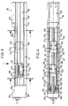
- Figures 3 to 6 show a concrete implementation example of the linear guide device shown only schematically in Fig. 2.
- the guide base 1b is formed by a profile guide housing 51b with a bottom wall 53b and two side walls 55b which are approximately perpendicular to the bottom wall 53b and parallel to one another.
- the bottom wall 53b and the side walls 55b define between them a guide cavity 57b, in which the rotor assembly 9b and the spindle support units are accommodated.
- FIGS. 3 and 4 only show one half of the linear guide device, only the spindle support units 27 1 b and 27 2 b can be seen, with spindle support units 29 1 a and 29 2 a of FIG.
- the guide housing 51b has a longitudinal opening 59b (see FIG. 4) through which the connection of the connecting part 23b of the rotor assembly 9b to the table 25b is established.
- the guide rail 3b is inserted into a bottom groove 61b in the side of the bottom wall 53b facing the guide cavity 57b and fastened there by means of fastening screws 63b.
- the spindle support units 27 1 b and 27 2 b each have a guide element 65b which guides the spindle support units on the guide rail 3b.
- the guide elements 65b and the rotor 21b of the rotor assembly 9b can be identical components, whereby standard series elements can be used. FIGS.
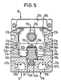
- FIG. 5 and 6 show that the rotor 21b of the rotor assembly 9b and the guide elements 65b of the spindle support units engage around the guide rail 3b in a U-shape, with two leg parts 66b arranged on both sides of the guide rail 3b being adjacent to side surfaces 68b of the guide rail 3b and with one the web parts 70b connecting the leg parts 66b lie adjacent to a head surface 72b of the guide rail 3b remote from the bottom wall 53b.
- Endless rolling element loops can be integrated in the leg parts 66b of the rotor 21b and the guide elements 65b, the load-transmitting rolling element sections of which are in rolling engagement with the guide surfaces 7b provided on the side surfaces 68b of the guide rail 3b.
- the spindle support units have a support element 67b, which is fastened to the respective guide element 65b and through which the drive spindle 13b passes.
- the support element 67b is designed as a sliding sleeve, preferably made of plastic, with a through bore 69b, the diameter of which is slightly larger than the diameter of the drive spindle 13b and in which the drive spindle 13b is slidably guided.
- the spindle support units have a clamping piece 71b which is attached to an end face of the respective spindle support unit and which provides the fixed points 33b, 35b or 43b, 45b for fastening the pull cables 31b and 41b.
- the clamping piece 71b can be fastened to the support element 67b or to the guide element 65b of the respective spindle support unit by means of fastening screws 73b (see FIG. 6). Further fastening screws 75b (see FIG. 4) serve to fasten the support element 67b to the guide element 65b of the respective spindle support unit.
- the guide housing 51b a plurality of undercut T-profile grooves 77b both on its outside and on the guide cavity 57b facing inside. These profile grooves 77b can be used to attach the guide housing 51b a higher-level construction or for fastening Attachments can be used on the guide housing 51b.
- the second traction rope 31''b of the traction cable 31b b is fixed to the fixed point 35b on the clamping piece 71b of the spindle support unit 27 1 and by a passage hole 81b (see Figure 6) 27 2 passed b movable in the clamping piece 71b of the spindle support unit.
- the returning run of the pull rope 31b formed by the pull rope section 31 ′′ b is guided in a hollow chamber 83b, which is formed separately from the guide cavity 57b in the bottom wall 53b of the guide housing 51b.
- the second pull cable section 41 ′′ b of the pull cable 41 b is fastened to the fixed point 45 b of the clamping piece 71 b of the spindle support unit 27 2 b, wherein the returning run of the pull cable 41 b formed by this second pull cable section 41 ′′ b is also guided in a hollow chamber 83 b of the guide housing 51 b is.
- the projection 79b on the left in the illustration belongs to the clamping piece 71b of the spindle support unit 27 2 b, while the projection 79b indicated on the right side of this clamping piece 71b belongs to the clamping piece 71b of the spindle support unit 27 1 b closer to the runner heard.
- the pull cable sections 31'b and 41'b and the associated fixed points 33b and 43b cannot be seen in this FIG. 6, since they are covered by the projections 79b in the viewing direction of FIG. 6.
- the guide cavity 57b is in the region of the longitudinal opening 59b covered by a masking tape 85b to prevent the ingress of To prevent dirt in the guide cavity 57b.
- the masking tape can be made of metal or plastic and either via suitable redirections by the rotor assembly 9b can be passed through or with the rotor assembly 9b in Drive connection stand and by deflecting the Ends of the guide housing 51b be deflected.
- Fig. 4 it can be seen that the deflection rollers 37b and 47b Deflection roller carriers 87b are mounted. This pulley carrier 87b are connected to mounting flanges 88b, which releasably attached to the ends of the guide housing 51b are.
- the deflection rollers 37b, 47b and the deflection roller carrier 87b are encapsulated by encapsulation elements 89b.
- the encapsulation elements 89b are mediated by the mounting flanges 88b at the ends of the guide housing 51b and are either on the mounting flanges 88b and / or on attached to the guide housing 51b so that the guide rollers 37b, 47b with the deflecting roller carriers 87b initially separately can be attached to the guide housing 51b and thereafter the encapsulation elements 89b can be attached.
- the encapsulation elements 89b can in turn be in one piece with the respective Traverse 39b be formed. This is a simplification guaranteed when assembling the linear guide device, because the pull cables 31b, 41b easily over the still unencapsulated guide rollers 37b, 47b and with the Spindle support units can be connected.
- the tensioning cables 31b, 41b can be tensioned, for example take place that the deflection rollers 37b, 47b relative to the deflection roller carriers 87b or this deflection roller carrier 87b opposite the guide housing 51b are adjustable.
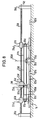
- FIG. 7 shows an exemplary embodiment in which two spindle support units 27 1 c and 29 1 c arranged axially on both sides of a rotor assembly 9c are coupled to the rotor assembly 9c by a drive cable 91c.
- the drive cable 91c causes a lower speed of the spindle support units 27 1 c and 29 1 c than the speed of movement of the rotor assembly 9c.
- the drive cable 91c comprises two cable sections 91'c and 91''c, both of which are attached at one end to a fixed point 93c on the rotor assembly 9c and at the other end to a fixed point 95c of the guide base 1c located approximately in the middle of the guide base 1c .
- the rope portion 91'c is guided by the fixed point 93c c of the rotor assembly via a guide roller 9c 97c on the spindle support unit 27 1 back to the fixed-point 95c to the guide base 1c.
- the rope portion 91''c is performed by the fixed point 93c c of the runner assembly 9c via a respective guide roller 99c on the spindle support unit 29 1 back to the associated fixed point 95c to the guide base 1c.
- the two spindle support units 27 1 c, 29 1 c are coupled to the rotor assembly 9c in the manner of a pulley, whereby in the present example this pulley connection causes the speeds of the spindle support units 27 1 c, 29 1 c to be halved compared to the speed of the rotor assembly 9 c .
- a rigid connecting rod 101c between the spindle support units 27 1 c, 29 1 c ensures the synchronism of the movements of the two spindle support units 27 1 c, 29 1 c.
- this connecting rod 101c can have a relatively small cross section since it does not have to absorb large thrust forces and accordingly there is no risk of kinking.
- the spindle support units 27 1 c, 29 1 c are in fact braked by the cable connection to the rotor assembly 9c when the speed of the rotor assembly 9c is reduced when one end of the guide base 1c is reached, so that they do not hit the respective end of the guide base 1c without being braked.
- the positioning of the spindle support units 27 1 c and 29 1 c with respect to the rotor assembly 9c is such that they are symmetrical to the rotor assembly 9c when the latter is in a central position designated 103c along the guide base 1c. They are arranged approximately in the middle between the rotor assembly and the associated end of the guide base 1c.
- This positioning of the spindle support units 27 1 c, 29 1 c, together with their movement speed halved compared to the rotor assembly 9c, causes the spindle support units 27 1 c, 29 1 c to have the respective longitudinal distance between the rotor assembly 9c and the associated end of the guide base 1c at all times in subdivide essentially equally long partial distances.
- Fig. 8 shows a modification of the linear guide device of Fig. 7, in which two spindle support units 27 1 d and 29 1 d are immovably arranged on a secondary guide rail 105d which is movably guided in rail guide units 107d which are fastened to the guide base 1d. If desired, a continuous guide bed for guiding the secondary guide rail 105d can be provided.
- the connecting rod 101c of FIG. 7 can be omitted because its spacing function is taken over by the guide rail 105d.
- the rotor assembly 9d is not guided directly on the guide base 1d, but on the guide rail 105d, which for this purpose has at least one separate guide surface 109d for the rotor assembly 9d.
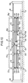
- FIG. 9 shows one possibility of combining the solutions according to FIGS. 1 and 7 with one another. Except for the now missing connecting rod 101c, the linear guide device shown in FIG. 9 corresponds to the embodiment of FIG. 7.
- This connecting rod 101c is replaced in FIG. 9 by a traction cable 31e, which has the same spacing and pair coupling function as the connecting rod 101c of FIG. 7 takes over.
- the pull rope 31e is closed to form an endless loop, wherein it engages at fixed points 33e, 35e on the spindle support units 27 1 e, 29 1 e, is guided movably past the rotor assembly 9e and through at the ends the guide base 1e mounted deflection rollers 37e is deflected.
- FIG. 10 shows a linear guide device in which two spindle support units 27 1 f, 27 2 f and 29 1 f, 29 2 f are arranged axially on both sides of the rotor assembly 9f.
- the spindle support units 27 1 f, 29 1 f closer to the rotor are coupled by a rigid connecting rod 101 f for synchronous movement.
- the spindle support units 27 2 f, 29 2 f which are further away from the rotor are coupled for synchronous movement by a connecting rod 111 f, which is only indicated by dashed lines.
- These two pairs of spindle support units are coupled to one another and to the rotor assembly 9f by a cable system such that when the rotor assembly 9f moves along the guide base 1f, the pair of spindle support units 27 1 f, 29 1 f closer to the rotor also move at a speed in the same direction, which is 2/3 of the speed of the rotor assembly 9f, and moves the pair of spindle support units 27 2 f, 29 2 f away from the rotor at a speed in the same direction which corresponds to 1/3 of the speed of the rotor assembly 9f.
- the spindle support units are positioned symmetrically with respect to the rotor assembly 9f, dividing the respective longitudinal distance between the rotor assembly 9f and the associated end of the guide base 1f into three approximately identical sections.
- This initial positioning of the spindle support units, together with the specified speed ratios, has the same effect as in the solution according to FIG. 7.
- the spindle support units between the rotor assembly 9f and this end of the Guide base 1f continuously against one another and against the rotor assembly 9f until finally they are immediately adjacent to one another when the relevant end of the guide base 1f is reached.
- the spindle support units between the rotor assembly 9f and the respective other end of the guide base 1f continuously move away from one another and ensure optimal support of the drive spindle 13f at equidistant intervals even when the rotor assembly 9f has assumed an end position along the guide base 1f.
- the mentioned cable system comprises a first pair of drive cables 113f, 115f, which start from a fixed point 117f on the rotor assembly 9f, are deflected for the first time by a first deflection roller 119f on the respective spindle support unit 27 2 f or 29 2 f, back to one run second deflection roller 121f mounted on the guide base 1f, are deflected there a second time and finally run again to a fixed point 123f on the respective spindle support unit 27 2 f or 29 2 f.
- These first drive cables 113f, 115f reduce the speed of the pair of spindle support units 27 2 f, 29 2 f to 1/3 the speed of the rotor assembly 9f.
- the cable system further comprises second drive cables 125f, 127f, which couple the pair of spindle support units 27 1 f, 29 1 f closer to the runner to the pair of spindle support units 27 2 f, 29 2 f which are further away from the runner.
- the drive cables 125f, 127f each run from a fixed point 129f on the guide base 1f to a third deflection roller 131f mounted on the respective spindle support unit 27 2 f or 29 2 f and from there after a single deflection back to a fixed point 133f on the respective spindle support unit 27 1 f or 29 1 f.
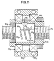
- the support nut 135g has at least a schematically indicated endless row of balls 137g on which is of a helical shape around the spindle axis extending section 139g, two to this section 139g subsequent arc sections 141g and one of the two Formed arc sections 141g connecting return section 143g is.
- the balls of section 139g are in one not shown helical thread groove in the inner circumferential surface of the support nut 135g. At the same time, they are aligned with the outer circumferential surface of the drive spindle 13g engaged, which - as before mentioned - threaded or smooth.
- the arc sections 141g and the return section 143g of the Row of balls 137g are in a return channel, not shown the support nut 135g.
- the support nut 135g can be a conventional series part, as it is for ordinary ones Ball screw drive is used. It is in one Sleeve 145g inserted and in this by means of a locking ring 147g and a stop shoulder 149g on the inner circumferential surface the sleeve 145g axially immovable. By a radially protruding nose 151g, which in an associated Recess in the inner peripheral surface of the sleeve 145g engages, the support nut 135g is non-rotatable with the sleeve 145g connected.
- the sleeve 145g is in turn in an outer ring via a ball or roller bearing device 153g, in particular a radial or angular contact ball bearing device 155g added.
- This 155g outer ring is non-rotatable Connection with the guide element (not shown in FIG. 11) 65b of a spindle support unit of the linear guide device according to Figures 3 to 6 or with a provided housing not shown, which ultimately on the guide base of the linear guide device is guided longitudinally.
Landscapes
- Engineering & Computer Science (AREA)
- General Engineering & Computer Science (AREA)
- Mechanical Engineering (AREA)
- Transmission Devices (AREA)
- Bearings For Parts Moving Linearly (AREA)
- Forwarding And Storing Of Filamentary Material (AREA)
- Guides For Winding Or Rewinding, Or Guides For Filamentary Materials (AREA)
Abstract
Description
Die Erfindung betrifft eine Linearführungseinrichtung, umfassend eine Führungsbasis mit einer Längsachse, eine relativ zu der Führungsbasis in Richtung der Längsachse geführte Läuferbaugruppe, eine Linearantriebseinrichtung zum Antrieb der Läuferbaugruppe längs der Längsachse, wobei diese Linearantriebseinrichtung eine an mindestens einem ihrer Enden relativ zur Führungsbasis axial fest, jedoch drehbar gelagerte Antriebsspindel sowie eine mit der Antriebsspindel in Gewindeeingriff stehende Mutter umfaßt, welche zur Bewegung in Richtung der Längsachse mit der Läuferbaugruppe verbunden ist und gegen Drehung mit der Antriebsspindel sperrbar oder bremsbar ist, je mindestens eine relativ zu der Läuferbaugruppe in Richtung der Längsachse an der Führungsbasis geführte Spindelunterstützungseinheit axial zu beiden Seiten der Läuferbaugruppe, welche in Abhängigkeit von Bewegungen der Läuferbaugruppe längs der Längsachse innerhalb des jeweiligen Längsabstands zwischen der Läuferbaugruppe und einem zugehörigen Spindelende verstellbar sind.The invention relates to a linear guide device, comprising a guide base with a longitudinal axis, one relative to the rotor base guided in the direction of the longitudinal axis, a linear drive device for driving the Rotor assembly along the longitudinal axis, this linear drive device one relative to at least one of its ends axially fixed to the guide base, but rotatably mounted Drive spindle and one with the drive spindle in threaded engagement standing mother who is moving to Direction of the longitudinal axis is connected to the rotor assembly and lockable against rotation with the drive spindle or is braked, at least one relative to the rotor assembly guided in the direction of the longitudinal axis on the guide base Spindle support unit axially on both sides the rotor assembly, which depends on movements the rotor assembly along the longitudinal axis within the respective Longitudinal distance between the rotor assembly and one associated spindle end are adjustable.
Die maximale Bewegungsgeschwindigkeit der Läuferbaugruppe relativ zur Führungsbasis hängt bei einer derartigen Linearführungseinrichtung von der sogenannten kritischen Drehzahl der Antriebsspindel ab. Bei Erreichen der kritischen Drehzahl wird die Antriebsspindel in Eigenschwingungen versetzt, deren Amplitude eine präzise Positionierung der Läuferbaugruppe unmöglich macht. Maßgebliche Faktoren, die die kritische Drehzahl bestimmen, sind der Durchmesser der Spindel und ihre Länge. Je kleiner das Durchmesser/Längen-Verhältnis der Antriebsspindel ist, desto niedriger liegen die kritische Drehzahl der Antriebsspindel und dementsprechend die maximale Bewegungsgeschwindigkeit der Läuferbaugruppe. Da insbesondere bei großen Längen der Antriebsspindel (z.B. mehreren Metern) der Spindeldurchmesser aus Abmessungs- bzw. Gewichtsgründen nicht beliebig vergrößert werden kann, werden zusätzliche Spindelunterstützungseinheiten in den unterstützungsfreien Längsabschnitten der Antriebsspindel zwischen der Läuferbaugruppe und den Spindelenden angeordnet. Die Spindelunterstützungseinheiten stellen zusätzliche Stützstellen für die Antriebsspindel dar und verkürzen die Länge der unterstützungsfreien Spindelabschnitte. Die kritische Drehzahl der Antriebsspindel und die maximale Bewegungsgeschwindigkeit der Läuferbaugruppe werden auf diese Weise erhöht. Darüber hinaus verhindern die Spindelunterstützungseinheiten speziell bei langen Antriebsspindeln Durchbiegungen der Antriebsspindel. Die Spindelunterstützungseinheiten sind relativ zu der Läuferbaugruppe beweglich und abhängig von einer Bewegung der Läuferbaugruppe längs der Längsachse verstellbar, so daß sie den durch die Spindellänge vorgegebenen maximalen Verstellweg der Läuferbaugruppe längs der Längsachse nur um ihre jeweilige Baulänge verkürzen.The maximum speed of movement of the rotor assembly hangs relative to the guide base in such a linear guide device from the so-called critical speed the drive spindle. When the critical speed is reached the drive spindle is set in natural vibrations, the Amplitude a precise positioning of the rotor assembly impossible makes. Relevant factors affecting the critical speed determine the diameter of the spindle and its Length. The smaller the diameter / length ratio of the drive spindle the lower the critical speed the drive spindle and accordingly the maximum Speed of movement of the rotor assembly. Because in particular with long lengths of the drive spindle (e.g. several meters) the spindle diameter for dimensional or weight reasons cannot be enlarged arbitrarily, additional ones will be Spindle support units in the support-free Longitudinal sections of the drive spindle between the rotor assembly and arranged the spindle ends. The spindle support units provide additional support points for the drive spindle and shorten the length of the support-free Spindle sections. The critical speed of the drive spindle and the maximum movement speed of the This increases the rotor assembly. Furthermore prevent the spindle support units especially at long drive spindles Deflections of the drive spindle. The spindle support units are relative to the rotor assembly agile and dependent on a movement of the Rotor assembly adjustable along the longitudinal axis so that it the maximum adjustment path specified by the spindle length the rotor assembly along the longitudinal axis only about their respective Shorten overall length.
Die Figuren 12 und 13 zeigen eine bekannte Ausführungsform.
Axial beidseits einer Läuferbaugruppe 9s ist dort je eine
Spindelunterstützungseinheit 27s, 29s angeordnet, die zusammen
mit der Läuferbaugruppe 9s auf einer Führungsschiene 3s
geführt sind. Die Läuferbaugruppe 9s ist mittels einer drehbaren
und axial feststehenden Antriebsspindel 13s längs der
Führungsschiene 3s antreibbar, wobei die Antriebsspindel 13s
mit einer relativ zur Läuferbaugruppe 9s axial feststehenden
und gegenüber dieser unverdrehbaren Spindelmutter in Eingriff
steht. Die beiden Spindelunterstützungseinheiten 27s, 29s
sind durch eine oder mehrere starre Verbindungsstangen 101s
in festem Abstand voneinander gehalten. Innerhalb des Längsabstands
zwischen den beiden Spindelunterstützungseinheiten
27s, 29s ist die Läuferbaugruppe 9s frei beweglich. Sobald
die Läuferbaugruppe 9s an einer der Spindelunterstützungseinheiten
27s, 29s anstößt, nimmt sie bei Weiterbewegung längs
der Führungsschiene 3s die beiden Spindelunterstützungseinheiten
27s, 29s in gleicher Richtung mit, und zwar schiebt
sie die in Bewegungsrichtung vor ihr liegende Spindelunterstützungseinheit
in unmittelbarer Anlage vor sich her, während
sie die in Bewegungsrichtung hinter ihr liegende Spindelunterstützungseinheit
im Abstand hinter sich herschleppt.
Wird die Läuferbaugruppe 9s weiter bis zum Ende der Führungsschiene
3s bewegt, so werden die beiden Spindelunterstützungseinheiten
27s, 29s durch Anschlag der in Bewegungsrichtung
vorderen Spindelunterstützungseinheit an einem geeigneten,
führungsschienenfesten Gegenanschlag abrupt abgebremst,
wobei die in Bewegungsrichtung hintere Spindelunterstützungseinheit
trägheitsbedingt nachschiebt. Die dabei auf die Verbindungsstangen
101s aufgebrachten Schubkräfte können, insbesondere
bei Vertikalanordnung, beachtlich sein, besonders
wenn man bedenkt, daß Verfahrgeschwindigkeiten der Läuferbaugruppe
9s in der Größenordnung von 1 m/s oder mehr nicht unüblich
sind und bei schweren durch die Linearführungseinrichtung
zu bewegenden Lasten auch die Spindelunterstützungseinheiten
27s, 29s entsprechend massiv gebaut sein
können. Um bei einer derartigen Schubbelastung nicht auszuknicken,
müssen die Verbindungsstangen 101s sehr schubsteif
sein und einen entsprechend großen Querschnitt haben, der in
einer beengten Einsatzumgebung der Linearführungseinrichtung
zu Platzproblemen führen kann. Dabei ist zu berücksichtigen,
daß auch bei gezielter Abbremsung der Läuferbaugruppe vor
Erreichen einer Endstellung diese gezielte Abbremsung der
jeweils vorlaufenden Spindelunterstützungseinheit nicht mitgeteilt
wird, weshalb diese vorlaufende Spindelunterstützungseinheit
mit dem ihr von der Läuferbaugruppe noch vor der
Abbremsung mitgeteilten Bewegungsimpuls gegen einen Anschlag
stoßen kann. Außerdem ist das vergleichsweise hohe Gewicht
der Verbindungsstangen 101s nachteilig, da einerseits die
Linearführungseinrichtung insgesamt schwerer wird, andererseits
die Verbindungsstangen 101s zu bewegende Massen darstellen. Figures 12 and 13 show a known embodiment.
There is one axially on both sides of a
Aus der EP 0 412 072 B1 ist eine Linearführungseinrichtung
mit einem Spindeltrieb bekannt, bei der axial beidseits einer
durch den Spindeltrieb zu bewegenden Läuferbaugruppe je eine
zusätzliche Stützmutter zur Abstützung der Spindel vorgesehen
ist. Die beiden Stützmuttern sind weder miteinander bewegungsmäßig
gekoppelt, noch stehen sie mit der Läuferbaugruppe
in Antriebsverbindung. Sie sind jeweils als mit der Spindel
im Gewindeeingriff stehende Kugelmutter ausgeführt, die sich
bei Drehung der Spindel mit etwa der halben Bewegungsgeschwindigkeit
der Läuferbaugruppe längs der Spindel fortbewegt.
Diese Geschwindigkeitsreduzierung wird durch eine Gestaltung
erreicht, bei der die Stützmuttern einen gegen Drehung
mit der Spindel gesicherten Außenteil umfassen, an dessen
Innenumfangsfläche mehrere zueinander parallele Kugellaufbahnen
ausgebildet sind, welche orthogonal zur Spindelachse
verlaufen, d.h. keine Steigung besitzen. Zwischen dem
Außenteil und der Spindel ist ein relativ zu dem Außenteil
drehbarer Kugelkäfig mit Ausnehmungen angeordnet, in denen
einzelne Kugeln aufgenommen sind. Diese Kugeln stehen mit den
Kugellaufbahnen des Außenteils und mit einem schraubenförmigen
Gewinde an der Außenumfangsfläche der Spindel in Eingriff.
Um die angegebene Geschwindigkeitsreduzierung zu erreichen,
müssen die Gewindesteigung der Spindel, das Radialspiel
bzw. die Radialvorspannung der Kugeln zwischen den
Laufbahnen des Außenteils und dem Gewinde der Spindel sowie
das Radialspiel bzw. die Radialvorspannung in den Lagern zwischen
dem Kugelkäfig und dem Außenteil geeignet aufeinander
abgestimmt werden. Dies ist mit einem beträchtlichen Herstellungsaufwand
verbunden.A linear guide device is known from
Bei der EP 0 412 072 B1 sollen die Stützmuttern stets mittig
zwischen der Läuferbaugruppe und dem jeweiligen Spindelende
positioniert sein. Da jedoch die Stützmuttern nicht durch die
Läuferbaugruppe zwangsweise verstellt werden, kann es vorkommen,
daß sich eine ungleichmäßige Verteilung der Stützmuttern
einstellt, bei der ein großer Längsabschnitt der Spindel keine
zusätzliche Stützstelle besitzt und somit die Gefahr von
Durchbiegungen besteht. Dies hängt damit zusammen, daß sich
die Stützmuttern nicht exakt mit der halben Geschwindigkeit
der Läuferbaugruppe bewegen und unter Umständen längs der
Spindel bis zu einem Spindelende durchrutschen können.In
Der Erfindung liegt das technische Problem zugrunde, bei einer Linearführungseinrichtung der eingangs bezeichneten Art mit einfachen Mitteln und geringem Platzbedarf dieser Mittel die Spindelunterstützungseinheiten stets so längs der Antriebsspindel positionieren zu können, daß Durchbiegungen und Eigenschwingungen der Antriebsspindel wirksam vermieden sind.The invention is based on the technical problem of a Linear guide device of the type described in the introduction with simple means and a small footprint of these means the spindle support units always along the drive spindle to be able to position that deflections and Natural vibrations of the drive spindle are effectively avoided.
Zur Lösung dieser Problemstellung wird vorgeschlagen, daß zur gegenseitigen Abstimmung der Bewegungen der Spindelunterstützungseinheiten oder/und zur Herstellung der Abhängigkeit der Bewegungen der Spindelunterstützungseinheiten von der Bewegung der Läuferbaugruppe mindestens ein flexibles Zugmittel vorgesehen ist.To solve this problem, it is proposed that mutual coordination of the movements of the Spindle support units or / and for the manufacture of Dependence of the movements of the spindle support units at least one flexible movement of the rotor assembly Traction means is provided.
Die erfindungsgemäße Lösung eignet sich für beliebige Anwendungsfälle, beispielsweise zum Tragen eines Werkzeugs oder eines Werkstücks in einer Bearbeitungsmaschine oder zur Führung eines Meßträgers in einer Meßeinrichtung. Das mindestens eine flexible Zugmittel kann von einem monofilen Draht aus Kunststoff oder Metall, einem Seil, insbesondere einem Drahtseil, einem Band oder einem Riemen gebildet sein. Seine Vorteile liegen in einem geringen Gewicht und einem kleinen Platzbedarf. Diese Vorteile machen sich insbesondere bei sehr großen Spindellängen von mehreren Metern (beispielsweise bis zu 6 Meter oder mehr) bemerkbar, wenn man zum Vergleich die Abmessungen und das Gewicht der Verbindungsstangen der bekannten Ausführungsform heranzieht. Darüber hinaus fällt auch der Kostenaufwand für die flexiblen Zugmittel nur unwesentlich ins Gewicht.The solution according to the invention is suitable for any application, for example to carry a tool or of a workpiece in a processing machine or for guidance of a measuring carrier in a measuring device. At least A flexible traction device can be made from a monofilament wire Plastic or metal, a rope, in particular a wire rope, a band or a strap. Its advantages are light in weight and small Space requirements. These advantages are particularly noticeable at large spindle lengths of several meters (e.g. up to to 6 meters or more) if you compare the Dimensions and weight of the connecting rods of the known Embodiment uses. It also falls the cost of the flexible traction means only insignificant weight.
Für Linearführungseinrichtungen mit großen Spindellängen empfiehlt es sich, auf beiden Seiten der Läuferbaugruppe mehrere zusätzliche Stützstellen für die Antriebsspindel vorzusehen. Es wird daher in Weiterbildung der Erfindung vorgeschlagen, daß zu beiden Seiten der Läuferbaugruppe je mindestens zwei Spindelunterstützungseinheiten vorgesehen sind, wobei zwei der Läuferbaugruppe jeweils nähere Spindelunterstützungseinheiten auf beiden Seiten der Läuferbaugruppe ein läufernäheres Paar bilden und zwei der Läuferbaugruppe jeweils fernere Spindelunterstützungseinheiten auf beiden Seiten der Läuferbaugruppe ein läuferferneres Paar bilden und wobei zumindest innerhalb eines dieser Paare die Spindelunterstützungseinheiten in ihren Bewegungen gegenseitig abgestimmt sind. Durch die Paarbildung der Spindelunterstützungseinheiten und die gegenseitige Bewegungsabstimmung innerhalb dieser Paare können dabei in beiden Bewegungsrichtungen der Läuferbaugruppe gleiche Abstützverhältnisse für die Antriebsspindel erreicht werden.Recommended for linear guide devices with large spindle lengths there are several on both sides of the rotor assembly provide additional support points for the drive spindle. It is therefore proposed in a development of the invention that at least two on each side of the rotor assembly Spindle support units are provided, two each spindle support units closer to the rotor assembly one closer to the runner on both sides of the runner assembly Form a pair and two further away from the rotor assembly Spindle support units on both sides of the rotor assembly form a distant pair and at least the spindle support units within one of these pairs are mutually coordinated in their movements. By the pairing of the spindle support units and the mutual movement coordination within these pairs can thereby in both directions of movement of the rotor assembly same support ratios for the drive spindle will.
Bei einer ersten bevorzugten Ausführungsform der Erfindung ist vorgesehen, daß die Spindelunterstützungseinheiten mindestens eines Paars von beidseits der Läuferbaugruppe angeordneten Spindelunterstützungseinheiten durch mindestens ein gewünschtenfalls unter Einschluß von Schleifenschlußmitteln zu einer Schleife geschlossenes flexibles Paarkoppelungsmittel in ihren Bewegungen gegenseitig abgestimmt sind, welches an den Spindelunterstützungseinheiten angreift und im Bereich der Spindelenden durch Umlenkmittel umgelenkt ist. Das als Paarkoppelungsmittel eingesetzte flexible Zugmittel erfüllt bei dieser Ausführungsform die gleiche Funktion wie die starren Verbindungsstangen bei der bekannten Ausführungsform, nämlich die beiden beidseits der Läuferbaugruppe angeordneten Spindelunterstützungseinheiten in festem Abstand voneinander zu halten und so in ihren Bewegungen gegenseitig abzustimmen. Allerdings ist hier keine schubsteife Verbindung zwischen beiden Spindelunterstützungseinheiten mehr vorhanden; vielmehr wird bei Anstoßen einer der Spindelunterstützungseinheiten an einem Spindelende die jeweils andere Spindelunterstützungseinheit durch denjenigen Abschnitt des zugkraftübertragenden Paarkoppelungsmittels abgebremst, der von der einen Spindelunterstützungseinheit über die Umlenkmittel zu dieser anderen Spindelunterstützungseinheit verläuft und dort zugfest angreift. Obwohl diese Ausführungsform auf den ersten Blick einen gegenüber den Verbindungsstangen der bekannten Ausführungsform erhöhten Bauteilaufwand erscheinen läßt (wegen der Umlenkmittel an den Spindelenden), ist doch die besonders bei großen Spindellängen erhebliche Platz- und Gewichtseinsparung zu berücksichtigen, die diesen Bauteilaufwand rechtfertigt. Für den Fall, daß zwei oder mehr Paare von beidseits der Läuferbaugruppe angeordneten Spindelunterstützungseinheiten vorhanden sind, wird man zweckmäßigerweise die Spindelunterstützungseinheiten jedes dieser Paare durch ein flexibles Paarkoppelungsmittel miteinander koppeln.In a first preferred embodiment of the invention it is provided that the spindle support units at least a pair arranged on both sides of the rotor assembly Spindle support units by at least one if desired, including loop closures flexible pair coupling means closed in a loop their movements are mutually coordinated, which one attacks on the spindle support units and in the area the spindle ends are deflected by deflecting means. That as Coupling means used flexible traction means met in this embodiment the same function as the rigid Connecting rods in the known embodiment, namely the two arranged on both sides of the rotor assembly Spindle support units at a fixed distance from each other to hold and so coordinate their movements. However, there is no rigid connection between both spindle support units more available; much more becomes one of the spindle support units when bumped the other spindle support unit at one spindle end through that section of the traction transmitting Coupling means slowed down by one Spindle support unit via the deflection means to this other spindle support unit runs and there tensile attacks. Although this embodiment at first Take a look at the connecting rods of the well-known Embodiment may appear increased component expense (because the deflecting means at the spindle ends), but it is special Considerable space and weight savings with large spindle lengths to take into account that this component effort justifies. In the event that two or more pairs of spindle support units arranged on both sides of the rotor assembly are present, you will expediently Each of these pairs spindle support units by one Coupling flexible pair coupling means together.
Die Verstellung der Spindelunterstützungseinheiten bei Bewegung der Läuferbaugruppe kann dadurch erreicht werden, daß die Spindelunterstützungseinheiten eines durch ein flexibles Paarkoppelungsmittel gegenseitig bewegungsabgestimmten Paars von Spindelunterstützungseinheiten durch eine Anschlagverbindung zwischen der Läuferbaugruppe und jeweils einer der beiden Spindelunterstützungseinheiten verstellbar sind. Bei dieser Lösung nimmt die Läuferbaugruppe bei einer Bewegung in Richtung auf ein Spindelende das Paar von Spindelunterstützungseinheiten in gleicher Richtung und mit gleicher Geschwindigkeit mit. Da die Läuferbaugruppe dabei die in Bewegungsrichtung hinter ihr liegende Spindelunterstützungseinheit in axialem Abstand mitschleppt, ist bei einer Annäherung der Läuferbaugruppe an ein Spindelende stets gewährleistet, daß sich dann in dem Spindelabschnitt der Antriebsspindel zwischen der Läuferbaugruppe und dem jeweils anderen Spindelende in ausreichendem Abstand von der Läuferbaugruppe mindestens eine zusätzliche Stützstelle für die Antriebsspindel befindet. Sind mehrere Paare von beidseits der Läuferbaugruppe angeordneten Spindelunterstützungseinheiten vorhanden, so kann dieses Prinzip der Verstellung der Spindelunterstützungseinheiten durch eine Anschlagverbindung dahingehend ausgeweitet werden, daß die Spindelunterstützungseinheiten mindestens eines Paars von läuferferneren Spindelunterstützungseinheiten, die durch ein flexibles Paarkoppelungsmittel gegenseitig bewegungsabgestimmt sind, durch eine Anschlagverbindung zwischen einer läufernäheren Spindelunterstützungseinheit und jeweils einer der beiden läuferferneren Spindelunterstützungseinheiten verstellbar sind.The adjustment of the spindle support units when moving the rotor assembly can be achieved in that the spindle support units one by one flexible Coupling means of mutually motion-matched pairs of spindle support units through a stop connection between the rotor assembly and one of the two Spindle support units are adjustable. At this The rotor assembly picks up the solution during a movement Direction towards a spindle end the pair of spindle support units in the same direction and at the same speed With. Since the rotor assembly is in the direction of movement the spindle support unit behind it dragged along at an axial distance is in the process of approximation the rotor assembly is always guaranteed at one end of the spindle, that then in the spindle section of the drive spindle between the rotor assembly and the other end of the spindle at least a sufficient distance from the rotor assembly an additional support point for the drive spindle located. Are multiple pairs from either side of the rotor assembly arranged spindle support units available, so this principle of adjustment of the spindle support units can extended by a stop connection be that the spindle support units at least a pair of spindle support units further from the rotor, the one another through a flexible pair coupling means are motion-matched by a stop connection between a spindle support unit closer to the rotor and one of the two runners further away Spindle support units are adjustable.
Bei einer weiteren bevorzugten Ausführungsform der Erfindung ist vorgesehen, daß die Spindelunterstützungseinheiten mindestens eines Paars von beidseits der Läuferbaugruppe angeordneten Spindelunterstützungseinheiten durch Abstandshaltemittel in festem Abstand voneinander gehalten sind und daß diese Spindelunterstützungseinheiten mit der Läuferbaugruppe durch flexible Geschwindigkeitsveränderungsmittel in einer Antriebsverbindung stehen, welche bei Bewegung der Läuferbaugruppe längs der Längsachse den Spindelunterstützungseinheiten eine Bewegung in gleicher Richtung mit gegenüber der Bewegungsgeschwindigkeit der Läuferbaugruppe reduzierter Bewegungsgeschwindigkeit erteilt. Bei dieser Ausführungsform sind die Spindelunterstützungseinheiten permanent mit der Läuferbaugruppe gekoppelt. Wenn die Läuferbaugruppe abgebremst wird, beispielsweise bei Erreichen eines Spindelendes, werden zwangsweise auch die Spindelunterstützungseinheiten langsamer. Dadurch ist vermieden, daß bei Erreichen eines Spindelendes die sich zwischen der Läuferbaugruppe und diesem Spindelende befindenden Spindelunterstützungseinheiten ungebremst an dem betreffenden Spindelende anschlagen.In a further preferred embodiment of the invention it is provided that the spindle support units at least a pair arranged on both sides of the rotor assembly Spindle support units by means of spacers are kept at a fixed distance from each other and that these Spindle support units with the rotor assembly flexible means of speed change in a drive connection stand, which when moving the rotor assembly along the longitudinal axis of the spindle support units a movement in the same direction with the movement speed the rotor assembly with reduced movement speed granted. In this embodiment the spindle support units permanently with the rotor assembly coupled. When the rotor assembly brakes will, for example, when reaching a spindle end the spindle support units are also forced to be slower. This avoids that when reaching a spindle end between the rotor assembly and this spindle end located spindle support units without brakes strike at the relevant spindle end.
Der letzte Gedanke kann in allgemeiner Form dadurch ausgedrückt
werden, daß bei Vorhandensein von n Spindelunterstützungseinheiten
UEx zwischen der Läuferbaugruppe und einem
ersten Ende der Führungsbasis, nämlich Spindelunterstützungseinheiten
UE1 bis UEn, deren Abstand von der Läuferbaugruppe
mit von x = 1 bis
und
and
In diesem Fall unterteilen die zwischen der Läuferbaugruppe und dem betrachteten ersten Ende der Führungsbasis angeordneten Spindelunterstützungseinheiten den Längsabstand zwischen der Läuferbaugruppe und diesem ersten Ende der Führungsbasis stets in im wesentlichen gleiche Teilabstände, und zwar unabhängig von der momentanen Position der Läuferbaugruppe längs der Längsachse. Falls beispielsweise zwei Spindelunterstützungseinheiten zwischen der Läuferbaugruppe und dem ersten Ende der Führungsbasis vorhanden sind, bewegt sich bei Drehung der Antriebsspindel die Läuferbaugruppe mit der normierten Geschwindigkeit 1, die der Läuferbaugruppe nächste Spindelunterstützungseinheit UE1 mit der normierten Geschwindigkeit 2/3 und die folgende Spindelunterstützungseinheit UE2 mit der normierten Geschwindigkeit 1/3. Gleichzeitig wird in diesem Beispielfall der Spindelabschnitt zwischen der Läuferbaugruppe und dem ersten Ende der Führungsbasis zu allen Zeiten in drei annähernd gleich große Teilabschnitte unterteilt.In this case, the spindle support units arranged between the rotor assembly and the considered first end of the guide base always divide the longitudinal distance between the rotor assembly and this first end of the guide base into substantially equal partial distances, regardless of the current position of the rotor assembly along the longitudinal axis. For example, if there are two spindle support units between the rotor assembly and the first end of the guide base, when the drive spindle rotates, the rotor assembly moves with the normalized speed 1, the spindle support unit UE 1 closest to the rotor assembly with the normalized speed 2/3 and the following spindle support unit UE 2 with the normalized speed 1/3. At the same time, in this example, the spindle section between the rotor assembly and the first end of the guide base is divided into three sections of approximately the same size at all times.
Um auf axial beiden Seiten der Läuferbaugruppe eine gleichmäßige Verteilung der durch die Spindelunterstützungseinheiten gebildeten Stützstellen für die Antriebsspindel zu gewährleisten, wird vorgeschlagen, daß in einer Mittelstellung der Läuferbaugruppe zwischen einem ersten und einem zweiten Ende der Führungsbasis die Spindelunterstützungseinheiten des mindestens einen Paars annähernd gleichen Abstand von der Läuferbaugruppe haben. In diesem Fall ergeben sich gleiche Abstützverhältnisse für beide Bewegungsrichtungen der Läuferbaugruppe.To ensure a uniform axial on both sides of the rotor assembly Distribution of the spindle support units to ensure the support points formed for the drive spindle, it is proposed that in a middle position the Rotor assembly between first and second ends the guide base, the spindle support units of the at least a pair of approximately equal distance from the rotor assembly to have. In this case, the support conditions are the same for both directions of movement of the rotor assembly.
Die Geschwindigkeitsreduzierung durch das flexible Geschwindigkeitsveränderungsmittel kann nach Art eines Flaschenzugs erfolgen. Demgemäß wird vorgeschlagen, daß bei Vorhandensein nur eines Paars von Spindelunterstützungseinheiten die Antriebsverbindung zwischen der Läuferbaugruppe und diesen Spindelunterstützungseinheiten je ein flexibles Geschwindigkeitsveränderungsmittel umfaßt, welches von einem Festpunkt an der Führungsbasis über eine Durchlaufumlenkung an einem Festpunkt der jeweiligen Spindelunterstützungseinheit zu einem Festpunkt an der Läuferbaugruppe verläuft. Bei diesem Verlauf des flexiblen Geschwindigkeitsveränderungsmittels wird den Spindelunterstützungseinheiten eine Bewegung mit gegenüber der Läuferbaugruppe halbierter Geschwindigkeit erteilt. Werden für den speziellen Anwendungsfall mehr als zwei Spindelunterstützungseinheiten benötigt, so wird vorgeschlagen, daß bei Vorhandensein von zwei Paaren von Spindelunterstützungseinheiten die Antriebsverbindung für jede Zweiergruppe von Spindelunterstützungseinheiten UE1, UE2 zu beiden Seiten der Läuferbaugruppe je zwei flexible Geschwindigkeitsveränderungsmittel umfaßt, deren eines von einem Festpunkt an der Läuferbaugruppe über eine Durchlaufumlenkung an einem Festpunkt der Spindelunterstützungseinheit UE2, von dort zurück zu einer weiteren Durchlaufumlenkung an einem Festpunkt der Führungsbasis und von dort zu einem Festpunkt an der Spindelunterstützungseinheit UE2 verläuft und deren anderes von einem Festpunkt an der Führungsbasis über eine Durchlaufumlenkung an einem Festpunkt der Spindelunterstützungseinheit UE2 zurück zu einem Festpunkt an der Spindelunterstützungseinheit UE1 verläuft. Wird für die Geschwindigkeit der Läuferbaugruppe wiederum der normierte Wert 1 angesetzt, so bewegen sich in diesem Fall die Unterstützungseinheiten UE1 auf beiden Seiten der Läuferbaugruppe mit der normierten Geschwindigkeit 2/3, wohingegen sich die Spindelunterstützungseinheiten UE2 mit der normierten Geschwindigkeit 1/3 bewegen.The speed can be reduced by the flexible speed change means in the manner of a pulley. Accordingly, it is proposed that in the presence of only a pair of spindle support units, the drive connection between the rotor assembly and these spindle support units each comprises a flexible speed change means, which runs from a fixed point on the guide base via a continuous deflection at a fixed point of the respective spindle support unit to a fixed point on the rotor assembly. During this course of the flexible speed change means, the spindle support units are given a movement at a speed which is halved compared to the rotor assembly. If more than two spindle support units are required for the special application, it is proposed that, in the presence of two pairs of spindle support units, the drive connection for each group of two spindle support units UE 1 , UE 2 on each side of the rotor assembly comprises two flexible speed change means, one of which by one Fixed point on the rotor assembly via a continuous deflection at a fixed point of the spindle support unit UE 2 , from there back to a further continuous deflection at a fixed point on the guide base and from there to a fixed point on the spindle support unit UE 2 and the other of which runs from a fixed point on the guide base via one Pass-through deflection at a fixed point of the spindle support unit UE 2 runs back to a fixed point on the spindle support unit UE 1 . If the normalized value 1 is again used for the speed of the rotor assembly, then in this case the support units UE 1 move on both sides of the rotor assembly with the normalized speed 2/3, whereas the spindle support units UE 2 move with the normalized speed 1/3 .
Die Abstandshaltemittel können ein starres Verbindungsorgan umfassen. Dieses Verbindungsorgan kann beispielsweise ein einfacher Verbindungsstab sein. Dieser kann jedoch im Vergleich zu den Verbindungsstangen, die bei der eingangs diskutierten bekannten Ausführungsform eingesetzt wurden, einen schwächeren Querschnitt besitzen, da er keine großen Schubkräfte aufnehmen muß, sondern lediglich dazu dient, den festen Abstand zwischen den beiden Spindelunterstützungseinheiten beizubehalten. Dabei ist zu berücksichtigen, daß wegen der ständigen Ankopplung der Spindelunterstützungseinheiten an die Läuferbaugruppe bei Abbremsung der Läuferbaugruppe die jeweils vorlaufende Spindelunterstützungseinheit ebenfalls abgebremst wird, so daß der Verbindungsstab allenfalls reduzierte Schubkräfte aufnehmen muß.The spacing means can be a rigid connecting element include. This connecting element can be, for example be a simple connecting rod. However, this can be compared to the connecting rods that were discussed at the beginning known embodiment were used, a have a weaker cross-section since it does not have large shear forces Must record, but only serves the fixed Distance between the two spindle support units maintain. It should be borne in mind that because of the constant coupling of the spindle support units to the rotor assembly when the rotor assembly is braked each leading spindle support unit also is braked so that the connecting rod at most reduced Must absorb thrust.
Denkbar ist es jedoch auch, daß die Abstandshaltemittel mindestens ein gewünschtenfalls unter Einschluß von Schleifenschlußmitteln zu einer Schleife geschlossenes flexibles Paarkoppelungsmittel umfassen, welches an den Spindelunterstützungseinheiten des jeweiligen Paars angreift und im Bereich der Spindelenden durch Umlenkmittel umgelenkt ist. Diese Lösung stellt eine Kombination eines flexiblen Paarkoppelungsmittels mit einem flexiblen Geschwindigkeitsveränderungsmittel dar und ermöglicht es, auf jegliches schubsteife Verbindungsorgan zwischen den Spindelunterstützungseinheiten zu verzichten, da man ausschließlich mit zugkraftübertragenden Mitteln zur Koppelung der Spindelunterstützungseinheiten untereinander und mit der Läuferbaugruppe auskommt.However, it is also conceivable that the spacing means at least one if desired, including loop closures flexible pair coupling means closed in a loop include, which on the spindle support units of each pair attacks and in the area the spindle ends are deflected by deflecting means. This solution represents a combination of a flexible pair coupling means with a flexible means of speed change and makes it possible to use any rigid connection element between the spindle support units too do without, since you only use traction-transmitting Means for coupling the spindle support units to one another and get along with the rotor assembly.
Häufig wird es genügen, wenn eine Spindelunterstützungseinheit einen aus einem gleitgünstigen Material, insbesondere Kunststoff, gefertigten Spindelumfassungskörper mit einer Durchgangsbohrung aufweist, welche von der Spindel gleitbeweglich durchsetzt ist. Dies kann z.B. eine Gleithülse sein. Es ist jedoch auch denkbar, in einer Spindelunterstützungseinheit eine in Gewindeeingriff mit der Antriebsspindel stehende Stützmutter vorzusehen. Man kann dann eine handelsübliche Mutter als Stützmutter verwenden, wie sie beispielsweise auch für den Antrieb der Läuferbaugruppe zum Einsatz kommt. Insbesondere kann man eine Kugelmutter mit mindestens einer endlosen Kugelreihe als Stützmutter verwenden. Eine solche Stützmutter kann eine perfekte Führung der Antriebsspindel in der Spindelunterstützungseinheit gewährleisten. Dabei ist jedoch folgendes zu bedenken: Im Falle der Verwendung eines flexiblen Geschwindigkeitsveränderungsmittels ergibt sich bei Bewegung der Läuferbaugruppe eine zwangsweise Mitbewegung der Spindelunterstützungseinheit, und zwar mit einer kleineren Geschwindigkeit als die Läuferbaugruppe. Im Falle, daß die Verstellbarkeit der Spindelunterstützungseinheit durch eine Anschlagverbindung mit der Läuferbaugruppe oder einer läufernäheren Spindelunterstützungseinheit gewährleistet ist, ergibt sich zeitweilig die Situation eines Stillstands der Spindelunterstützungseinheit bei Bewegung der Läuferbaugruppe. Wenn nun die Stützmutter gegen Drehung mit der Antriebsspindel gesperrt wäre, würde sie sich bei Drehung der Antriebsspindel mit der gleichen Geschwindigkeit wie die Läuferbaugruppe bewegen. Daher muß eine Ausgleichsmöglichkeit geschaffen werden, damit sich die jeweilige Spindelunterstützungseinheit mit einer anderen Geschwindigkeit (ggf. Geschwindigkeit Null) als die Läuferbaugruppe bewegen kann. Diese Ausgleichsmöglichkeit kann darin bestehen, daß die Stützmutter in der Spindelunterstützungseinheit axial unbeweglich, aber derart drehbar gelagert ist, daß eine einer vorgegebenen Abhängigkeit zwischen der Bewegung der Läuferbaugruppe und der Bewegung der jeweiligen Spindelunterstützungseinheit entsprechende Geschwindigkeitsdifferenz dieser beiden Längsbewegungen durch Rotation der Stützmutter ermöglicht ist. Dabei wird man die Steigung des von der Antriebsspindel und der Stützmutter gebildeten Gewindetriebs, die durch Radialspiel oder Radialvorspannung bestimmten Reibungsverhältnisse zwischen Stützmutter und Antriebsspindel sowie die Reibungsverhältnisse innerhalb der zwischen der Stützmutter und der Spindelunterstützungseinheit angeordneten Lager geeignet aufeinander abstimmen, um die jeweilige Fallkonstellation (z. B. Stillstand der Spindelunterstützungseinheit bei Längsbewegung der Läuferbaugruppe) verwirklichen zu können.Often it will suffice if a spindle support unit one made of a low-friction material, in particular Plastic, manufactured spindle body with a Has through bore which slidably from the spindle is enforced. This can e.g. be a sliding sleeve. However, it is also conceivable in a spindle support unit one in threaded engagement with the drive spindle Support nut. You can then get a commercial one Use the mother as a support nut, for example also used to drive the rotor assembly is coming. In particular, you can have a ball nut with at least an endless row of balls as a support nut. A such support nut can provide perfect guidance of the drive spindle ensure in the spindle support unit. However, the following should be considered: In case of use of a flexible speed change means a forced movement of the rotor assembly Co-movement of the spindle support unit, with at a lower speed than the rotor assembly. in the Case that the adjustability of the spindle support unit through a stop connection with the rotor assembly or a spindle support unit closer to the rotor the situation of one temporarily arises The spindle support unit stops when the Rotor assembly. If now the support nut against rotation with the drive spindle would be locked, it would turn when rotating the drive spindle at the same speed as that Move the rotor assembly. Therefore there must be a possibility of compensation be created so that the respective spindle support unit at a different speed (possibly speed Zero) than the rotor assembly can move. This possibility of compensation may consist in that Support nut in the spindle support unit axially immobile, but is rotatably mounted so that one predetermined dependency between the movement of the rotor assembly and the movement of the respective spindle support unit corresponding speed difference this allows both longitudinal movements by rotating the support nut is. Doing so will increase the slope of the drive spindle and the support nut formed screw drive friction conditions determined by radial play or radial preload between support nut and drive spindle as well the friction within the between the support nut and the spindle support unit arranged bearings suitably coordinate with each other to the respective case constellation (e.g. standstill of the spindle support unit at Longitudinal movement of the rotor assembly) can be realized.
Die Verwendung einer Stützmutter in einer Spindelunterstützungseinheit hat darüber hinaus den Vorteil einer hohen Verschleißfestigkeit. Wenn man zur Unterstützung der Antriebsspindel eine Gleithülse verwendet, so kann insbesondere bei gerollten Spindeln, also Spindeln mit einer durch ein Rollenwerkzeug hergestellten Gewindenut, ein Abrieb der Gleithülse durch Materialaufwerfungen auftreten, die beim Rollen der Spindel zwischen einzelnen Windungen entstehen können. Zwar ist dieser Abrieb bei geschliffenen Spindeln geringer. Dennoch kann man durch Verwendung einer Stützmutter, insbesondere einer Kugelmutter, den Verschleiß in der Spindelunterstützungseinheit erheblich reduzieren.The use of a support nut in a spindle support unit also has the advantage of high wear resistance. If you support the drive spindle a sliding sleeve is used, so can in particular rolled spindles, i.e. spindles with a through a roller tool manufactured thread groove, abrasion of the sliding sleeve due to material peaks that occur when rolling the Spindle can arise between individual turns. Though this abrasion is less with ground spindles. Yet can be done by using a support nut, in particular a ball nut, the wear in the spindle support unit reduce significantly.
Die Führungsbasis kann mindestens eine Führungsfläche aufweisen, an der sowohl die Läuferbaugruppe als auch Spindelunterstützungseinheiten geführt sind. Alternativ kann zur Führung der Spindelunterstützungseinheiten und der Läuferbaugruppe mindestens je eine gesonderte Führungsfläche an der Führungsbasis vorgesehen sein. Anstatt die Läuferbaugruppe unmittelbar auf der Führungsbasis zu führen, ist es auch denkbar, daß an der Führungsbasis eine Sekundärführungsschiene geführt ist, auf welcher zwei Spindelunterstützungseinheiten unbeweglich angeordnet sind, und daß die Läuferbaugruppe auf dieser Sekundärführungsschiene relativ zu den beiden Spindelunterstützungseinheiten in Richtung der Längsachse beweglich geführt ist.The guide base can have at least one guide surface, on both the rotor assembly and spindle support units are led. Alternatively, for guidance the spindle support units and the rotor assembly at least one separate guide surface each on the guide base be provided. Instead of the rotor assembly immediately to lead on the leadership base, it is also conceivable that guided on the guide base a secondary guide rail on which two spindle support units are immobile are arranged, and that the rotor assembly on this Secondary guide rail relative to the two spindle support units movably guided in the direction of the longitudinal axis is.
Die Erfindung ist nicht auf eine bestimmte Gestaltung der Führungsbasis beschränkt. Die Führungsbasis kann z.B. von einem massiven Trägerbett gebildet sein, auf dem eine oder mehrere Führungsschienen befestigt sind. Bei einer bevorzugten Ausführungsform ist vorgesehen, daß die Führungsbasis ein Führungsgehäuse mit einen Führungshohlraum begrenzenden Wänden umfaßt und die Läuferbaugruppe und die Spindelunterstützungseinheiten in dem Führungshohlraum aufgenommen sind, wobei die Läuferbaugruppe eine Längsöffnung des Führungsgehäuses durchsetzt und außerhalb des Führungshohlraums zur Aufnahme eines in Richtung der Längsachse zu bewegenden Objekts ausgebildet ist. Dabei kann dann innerhalb des Führungsholhraums mindestens eine Führungsschiene für die Führung der Läuferbaugruppe oder/und der Spindelunterstützungseinheiten an dem Führungsgehäuse befestigt sein. Die Läuferbaugruppe und die Spindelunterstützungseinheiten sind bevorzugt durch Wälzkörper an der Führungsbasis geführt, beispielsweise durch Kugeln, tonnenförmige Rollen oder scheibenförmige Laufrollen. Insbesondere können die Läuferbaugruppe oder/und die Spindelunterstützungseinheiten mindestens eine endlose Wälzkörperschleife zu ihrer Führung auf der Führungsbasis aufweisen. Es ist aber auch eine Gleitlagerung der Läuferbaugruppe und der Spindelunterstützungseinheiten denkbar.The invention is not limited to any particular design Management base limited. The leadership base can e.g. from be formed a solid carrier bed on which one or several guide rails are attached. In a preferred one Embodiment is provided that the guide base Guide housing with walls delimiting a guide cavity includes and the rotor assembly and the spindle support units are received in the guide cavity, wherein the rotor assembly has a longitudinal opening in the guide housing interspersed and outside the guide cavity for receiving an object to be moved in the direction of the longitudinal axis is trained. This can then be done within the guide cavity at least one guide rail for guiding the Rotor assembly or / and the spindle support units be attached to the guide housing. The rotor assembly and the spindle support units are preferred by Rolling elements guided on the guide base, for example by Balls, barrel-shaped rollers or disc-shaped rollers. In particular, the rotor assembly and / or the spindle support units at least one endless rolling element loop have for their leadership on the leadership base. It is also a slide bearing of the rotor assembly and the Spindle support units conceivable.
Zweckmäßigerweise verläuft das mindestens eine flexible Zugmittel wenigstens zum Teil innerhalb des Führungshohlraums. Dies bietet sich an, weil das mindestens eine flexible Zugmittel auf diese Weise vor Beschädigung und Verschmutzung geschützt ist. Besonders vorteilhaft ist es dann, wenn das mindestens eine flexible Zugmittel zumindest auf einem Teil seiner Länge in einer zum Führungshohlraum hin offenen Zugmittelaufnahmenut aufgenommen ist, welche in einer der den Führungshohlraum begrenzenden Wände ausgebildet ist. Einerseits wird das mindestens eine flexible Zugmittel in der Zugmittelaufnahmenut perfekt geschützt, andererseits kann so auch bei beengten Platzverhältnissen innerhalb des Führungshohlraums das mindestens eine flexible Zugmittel wenigstens zum Teil innerhalb des Führungshohlraums geführt werden. Wenn das Führungsgehäuse ein Profilgehäuse mit einer oder mehreren längsverlaufenden Befestigungsnuten ist, kann vorteilhafterweise eine dieser Befestigungsnuten ohne konstruktiven Mehraufwand als Zugmittelaufnahmenut dienen.The at least one flexible traction device expediently runs at least in part within the guide cavity. This lends itself because the at least one flexible traction device this way from damage and pollution is protected. It is particularly advantageous if that at least one flexible traction device on at least one part its length in a traction means receiving groove open towards the guide cavity is recorded, which in one of the Guide cavity delimiting walls is formed. On the one hand the at least one flexible traction device is groove in the traction device receptacle perfectly protected, on the other hand it can even in confined spaces within the guide cavity the at least one flexible traction means at least are partially guided within the guide cavity. If the guide housing is a profile housing with one or more longitudinal fastening grooves can be advantageous one of these fastening grooves without additional design effort serve as a traction device groove.
Zweckmäßigerweise wird das in der Zugmittelaufnahmenut aufgenommene Zugmittel oder dessen jeweiliger Teil an einem dieser Zugmittelaufnahmenut benachbarten Umrißbereich der Läuferbaugruppe oder/und mindestens einer Spindelunterstützungseinheit beweglich vorbeigeführt oder befestigt sein. Dabei kann das in der Zugmittelaufnahmenut aufgenommene Zugmittel oder dessen jeweiliger Teil an einem Vorsprung der Läuferbaugruppe oder/und einem Vorsprung mindestens einer Spindelunterstützungseinheit befestigt sein, welcher in die Zugmittelaufnahmenut hineinragt.Expediently, that which is accommodated in the traction means receiving groove Traction means or its respective part on one of these Traction device recordings in the adjacent outline area of the rotor assembly or / and at least one spindle support unit be movably guided past or fastened. It can traction means accommodated in the traction means receiving groove or its respective part on a projection of the rotor assembly or / and a projection of at least one spindle support unit be attached, which in the Zugmittelaufnahmut protrudes.
Eine weitere geschützte Unterbringungsart für das mindestens eine flexible Zugmittel kann darin bestehen, daß es zumindest auf einem Teil seiner Länge in einem von dem Führungshohlraum getrennten Zugmittelaufnahmekanal verläuft. Diese Lösung bietet sich insbesondere dann an, wenn das mindestens eine flexible Zugmittel als flexibles Paarkoppelungsmittel ausgebildet ist. Man kann dann ein rücklaufendes Trum dieses flexiblen Paarkoppelungsmittels in dem Zugmittelaufnahmekanal führen und im Bereich der zugehörigen Umlenkmittel aus dem Zugmittelaufnahmekanal austreten lassen.Another protected type of accommodation for the least A flexible traction device can consist of at least along part of its length in one of the guide cavity separate traction device receiving channel runs. This solution offers especially when the at least one flexible Traction means designed as a flexible pair coupling means is. You can then make a returning run of this flexible Guide pair coupling means in the traction device receiving channel and in the area of the associated deflection means from the traction means receiving channel let out.
Um die in dem Führungshohlraum aufgenommenen Komponenten, wie etwa die Läuferbaugruppe, die Spindelunterstützungseinheiten sowie gegebenenfalls das mindestens eine flexible Zugmittel, gegen Eindringen von Schmutz zu schützen, ist der Führungshohlraum im Bereich seiner Längsöffnung bevorzugt durch ein Abdeckband abgedeckt, welches entweder mit der Läuferbaugruppe in Antriebsverbindung steht oder durch die Läuferbaugruppe hindurchgeführt ist.To the components received in the guide cavity, such as such as the rotor assembly, the spindle support units and optionally the at least one flexible traction device, The guiding cavity is to protect against the ingress of dirt preferably in the area of its longitudinal opening by a Masking tape covered, which either with the rotor assembly in drive connection or through the rotor assembly is passed through.
Zur Vereinfachung der Montage der erfindungsgemäßen Linearführungseinrichtung wird weiter vorgeschlagen, daß das mindestens eine flexible Zugmittel oder/und ein mit der Läuferbaugruppe in Antriebsverbindung stehendes Abdeckband in mindestens einem Endbereich des Führungsgehäuses über ein durch Kapselungsmittel gekapseltes Umlenkmittel verläuft, wobei dieses Umlenkmittel gesondert von den Kapselungsmitteln in dem betreffenden Endbereich des Führungsgehäuses anbringbar ist und das zugehörige Kapselungsmittel nach Anbringung des Umlenkmittels in Kapselungsstellung gegenüber dem Umlenkmittel an dem Führungsgehäuse oder/und an einer Führungsschiene dieses Führungsgehäuses oder/und an dem Umlenkmittel befestigbar ist. Es kann dann nämlich zunächst das Umlenkmittel ohne zugehöriges Kapselungsmittel angebracht werden, so daß anschließend das mindestens eine flexible Zugmittel oder/und das Abdeckband ohne Behinderung durch das Kapselungsmittel problemlos aufgelegt werden können. Die Anbringung des Kapselungsmittels erfolgt erst im Anschluß daran.To simplify the assembly of the linear guide device according to the invention it is further suggested that at least a flexible traction device and / or one with the rotor assembly cover tape in drive connection in at least an end region of the guide housing via a through Encapsulated encapsulated deflecting means, where this deflection means separate from the encapsulation means in can be attached to the relevant end region of the guide housing and the associated encapsulant after attaching the Deflection means in the encapsulation position relative to the deflection means on the guide housing and / or on a guide rail this guide housing and / or attachable to the deflecting means is. It can then first of all be the deflecting means be attached without the associated encapsulant so that then the at least one flexible traction device and / or the masking tape without obstruction by the encapsulant can be put on easily. The attachment of the encapsulant takes place only afterwards.
Der vorstehend diskutierte Gedanke, eine Spindelunterstützungseinheit mit einer in Gewindeeingriff mit der Antriebsspindel stehenden Stützmutter auszuführen, soll im Rahmen der Erfindung auch selbständigen Schutz genießen. Die Erfindung betrifft demnach ferner eine Linearführungseinrichtung, umfassend eine Führungsbasis mit einer Längsachse, eine relativ zu der Führungsbasis in Richtung der Längsachse geführte Läuferbaugruppe, eine Linearantriebseinrichtung zum Antrieb der Läuferbaugruppe längs der Längsachse, wobei diese Linearantriebseinrichtung eine an mindestens einem ihrer Enden relativ zur Führungsbasis axial fest, jedoch drehbar gelagerte Antriebsspindel sowie eine mit der Antriebsspindel in Gewindeeingriff stehende Mutter umfaßt, welche zur Bewegung in Richtung der Längsachse mit der Läuferbaugruppe verbunden ist und gegen Drehung mit der Antriebsspindel sperrbar oder bremsbar ist, mindestens eine relativ zu der Läuferbaugruppe in Richtung der Längsachse an der Führungsbasis geführte Spindelunterstützungseinheit, welche in Abhängigkeit von Bewegungen der Läuferbaugruppe längs der Längsachse innerhalb des Längsabstands zwischen der Läuferbaugruppe und einem zugehörigen Spindelende verstellbar ist, wobei die Linearführungseinrichtung gewünschtenfalls nach der vorstehenden Art ausgestaltet ist. Erfindungsgemäß ist dabei vorgesehen, daß die mindestens eine Spindelunterstützungseinheit eine in Gewindeeingriff mit der Antriebsspindel stehende Stützmutter umfaßt, welche in der Spindelunterstützungseinheit axial unbeweglich, aber derart drehbar gelagert ist, daß eine einer vorgegebenen Abhängigkeit zwischen der Bewegung der Läuferbaugruppe und der Bewegung der Spindelunterstützungseinheit entsprechende Geschwindigkeitsdifferenz dieser beiden Längsbewegungen (z. B. Stillstand der Spindelunterstützungseinheit bei Längsbewegung der Läuferbaugruppe) durch Rotation der Stützmutter ermöglicht ist.The idea discussed above, a spindle support unit with one in threaded engagement with the drive spindle Execute standing support nut should be within the scope of Invention also enjoy independent protection. The invention accordingly further relates to a linear guide device comprising a guide base with a longitudinal axis, a relative rotor assembly guided to the guide base in the direction of the longitudinal axis, a linear drive device for driving the Rotor assembly along the longitudinal axis, this linear drive device one relative to at least one of its ends axially fixed to the guide base, but rotatably mounted Drive spindle and one with the drive spindle in threaded engagement standing mother who is moving to Direction of the longitudinal axis is connected to the rotor assembly and lockable against rotation with the drive spindle or is brakable, at least one relative to the rotor assembly guided in the direction of the longitudinal axis on the guide base Spindle support unit, which depends on movements the rotor assembly along the longitudinal axis within the longitudinal distance between the rotor assembly and an associated one Spindle end is adjustable, the linear guide device if desired according to the above Art is designed. According to the invention it is provided that the at least one spindle support unit is in threaded engagement support nut standing with the drive spindle which is axially immovable in the spindle support unit, but is rotatably mounted so that one predetermined dependency between the movement of the rotor assembly and the movement of the spindle support unit corresponding speed difference of these two longitudinal movements (e.g. standstill of the spindle support unit with longitudinal movement of the rotor assembly) by rotating the Support nut is enabled.
Bevorzugt läßt sich dieser Gedanke bei einer Spindelunterstützungseinheit anwenden, die einen Kugelgewindetrieb mit mindestens einer endlosen Kugelreihe umfaßt, welche auf einem Teil ihrer Länge einem Gewindeweg an der Innenumfangsfläche der Stützmutter folgt und auf einem Restweg durch einen Rücklaufkanal der Stützmutter verläuft.This idea can preferably be applied to a spindle support unit apply using a ball screw comprises at least one endless row of balls on a Part of its length is a thread path on the inner peripheral surface the support nut follows and on a remaining path through a return channel the support nut runs.
Die Erfindung wird im folgenden anhand einiger bevorzugter Ausführungsbeispiele näher erläutert. Es stellen dar:
- Fig. 1
- schematisch eine erste Ausführungsform der erfindungsgemäßen Linearführungseinrichtung mit zwei beidseits einer Läuferbaugruppe angeordneten Spindelunterstützungseinheiten, die über ein flexibles Paarkoppelungsmittel gegenseitig bewegungsabgestimmt sind,
- Fig. 2
- schematisch eine weitere Ausführungsform der erfindungsgemäßen Linearführungseinrichtung, die die Ausführungsform nach der Fig. 1 insofern ergänzt, als sie zusätzlich ein zweites Paar von beidseits der Läuferbaugruppe angeordneten Spindelunterstützungseinheiten aufweist, die ebenfalls über ein flexibles Paarkoppelungsmittel in ihren Bewegungen gegenseitig abgestimmt sind,
- Fig. 3
- eine Ansicht von der Seite her auf ein konkretes Realisierungsbeispiel einer Linearführungseinrichtung nach der Fig. 2,
- Fig. 4.
- eine Ansicht von oben auf die Linearführungseinrichtung der Fig. 3,
- Fig. 5
- einen Schnitt längs der Linie V-V der Fig. 3,
- Fig. 6
- einen Schnitt längs der Linie VI-VI der Fig. 3,
- Fig. 7
- schematisch eine weitere Ausführungsform der erfindungsgemäßen Linearführungseinrichtung, bei der zwei beidseits einer Läuferbaugruppe angeordnete Spindelunterstützungseinheiten durch ein flexibles Geschwindigkeitsveränderungsmittel an die Läuferbaugruppe angekoppelt sind,
- Fig. 8
- schematisch eine Abwandlung der Linearführungseinrichtung der Fig. 7,
- Fig. 9
- schematisch eine weitere Ausführungsform der erfindungsgemäßen Linearführungseinrichtung, bei der zwei beidseits einer Läuferbaugruppe angeordnete Spindelunterstützungseinheiten einerseits durch ein flexibles Paarkoppelungsmittel in ihren Bewegungen gegenseitig abgestimmt sind, andererseits durch ein flexibles Geschwindigkeitsveränderungsmittel an die Läuferbaugruppe angekoppelt sind,
- Fig. 10
- schematisch eine weitere Ausführungsform der erfindungsgemäßen Linearführungseinrichtung, bei der beidseits einer Läuferbaugruppe zwei Paare von Spindelunterstützungseinheiten angeordnet sind, die durch eine Mehrzahl von flexiblen Geschwindigkeitsveränderungsmitteln sowohl untereinander als auch mit der Läuferbaugruppe gekoppelt sind,
- Fig. 11
- ein Ausführungsbeispiel einer Spindelunterstützungseinheit mit einer in Gewindeeingriff mit einer Antriebsspindel stehenden Stützmutter,
- Fig. 12
- eine Ansicht von der Seite her auf eine Linearführungseinrichtung nach dem Stand der Technik und
- Fig. 13
- eine Ansicht von oben her auf die Linearführungseinrichtung der Fig. 12.
- Fig. 1
- schematically a first embodiment of the linear guide device according to the invention with two spindle support units arranged on both sides of a rotor assembly, which are mutually motion-coordinated via a flexible pair coupling means,
- Fig. 2
- schematically shows a further embodiment of the linear guide device according to the invention, which supplements the embodiment according to FIG. 1 insofar as it additionally has a second pair of spindle support units arranged on both sides of the rotor assembly, the movements of which are also mutually coordinated via a flexible pair coupling means,
- Fig. 3
- 2 shows a view from the side of a concrete implementation example of a linear guide device according to FIG. 2,
- Fig. 4.
- 3 shows a view from above of the linear guide device of FIG. 3,
- Fig. 5
- 4 shows a section along the line VV in FIG. 3,
- Fig. 6
- a section along the line VI-VI of Fig. 3,
- Fig. 7
- schematically another embodiment of the linear guide device according to the invention, in which two spindle support units arranged on both sides of a rotor assembly are coupled to the rotor assembly by a flexible speed change means,
- Fig. 8
- schematically a modification of the linear guide device of FIG. 7,
- Fig. 9
- schematically a further embodiment of the linear guide device according to the invention, in which two spindle support units arranged on both sides of a rotor assembly are mutually coordinated in their movements on the one hand by a flexible pair coupling means and on the other hand are coupled to the rotor assembly by a flexible speed change means,
- Fig. 10
- schematically shows a further embodiment of the linear guide device according to the invention, in which two pairs of spindle support units are arranged on both sides of a rotor assembly, which are coupled both to one another and to the rotor assembly by a plurality of flexible speed change means,
- Fig. 11
- 1 shows an exemplary embodiment of a spindle support unit with a support nut which is in threaded engagement with a drive spindle,
- Fig. 12
- a view from the side of a linear guide device according to the prior art and
- Fig. 13
- a view from above of the linear guide device of FIG. 12th
In Fig. 1 ist eine Führungsbasis 1 gezeigt, auf der eine Führungsschiene
3 mit einer Längsachse 5 befestigt ist. Die Führungsschiene
3 weist mindestens eine Führungsfläche 7 auf, an
der eine Läuferbaugruppe 9 längs der Längsachse 5 verschiebbar
geführt ist. Der Antrieb der Läuferbaugruppe 9 längs der
Längsachse 5 erfolgt mittels einer Spindelantriebseinrichtung
11, welche eine Antriebsspindel 13 mit einer zur Längsachse 5
parallelen Spindelachse sowie eine mit der Antriebsspindel 13
in Gewindeeingriff stehende Mutter 15 umfaßt. Die Antriebsspindel
13 ist an ihren Enden drehbar gelagert, und zwar an
ihrem in Fig. 1 rechten Ende in einem schematisch angedeuteten
Festlager 17, welches die Antriebsspindel 13 axial fest
hält, und an ihrem in Fig. 1 linken Ende in einem ebenfalls
nur schematisch angedeuteten Loslager 19, welches axiale Ausgleichsbewegungen
der Antriebsspindel 13 beispielsweise aufgrund
thermischer Ausdehnung erlaubt. Auf der Seite des Festlagers
17 kann die Antriebsspindel 13 durch einen nicht näher
dargestellten Antriebsmotor, beispielsweise einen Elektromotor,
in Drehung versetzt werden. Die Mutter 15 ist axial unbeweglich
und verdrehsicher mit der Läuferbaugruppe 9 verbunden,
so daß bei einer Drehung der Antriebsspindel 13 die Läuferbaugruppe
9 mit einer Geschwindigkeit längs der Längsachse
5 bewegt wird, welche dem Produkt der Drehzahl der Antriebsspindel
13 und der Steigung des zwischen der Antriebsspindel
13 und der Mutter 15 gebildeten Gewindes entspricht. Die Läuferbaugruppe
9 umfaßt einen auf der Führungsschiene 3 wälz- oder
gleitgelagerten Läufer 21, welcher mit einem die Mutter
15 aufnehmenden Anschlußteil 23 verbunden ist. Auf dem Anschlußteil
23 ist ein Tisch 25 befestigt, auf den ein zu bewegendes
Objekt, beispielsweise ein Werkzeug oder ein Werkstück,
aufgesattelt werden kann. Die Läuferbaugruppe 9 muß
jedoch nicht in dieser Weise als Träger zu bewegender Lasten
ausgeführt sein. Anstelle des Tisches 25 kann auch ein Mitnehmer
vorgesehen sein, der in Eingriff mit einem zu bewegenden
Objekt steht, ohne dabei eine Lasttragefunktion zu übernehmen.In Fig. 1, a guide base 1 is shown on which a guide rail
3 is fixed with a longitudinal axis 5. The guide rail
3 has at least one guide surface 7
the one
Der von der Antriebsspindel 13 und der Mutter 15 gebildete
Spindeltrieb ist vorzugsweise als Wälzkörperschraubtrieb,
insbesondere Kugelschraubtrieb, mit mindestens einem Wälzkörperumlauf
ausgebildet, welcher mit einer endlosen Reihe von
Wälzkörpern besetzt ist. Die Außenumfangsfläche der Antriebsspindel
13 kann dabei mindestens eine schraubenförmig um die
Spindelachse verlaufende Gewindenut aufweisen, in die die
Wälzkörper des Wälzkörperumlaufs eingreifen. Es ist aber auch
denkbar, eine an ihrer Außenumfangsfläche glatte Antriebsspindel
13 zu verwenden, bei der die lastübertragenden Wälzkörper
zwischen der Mutter 15 und der Antriebsspindel 13 derart
radial vorgespannt sind, daß eine axiale Fortbewegung
der Mutter 15 infolge des Reibeingriffs zwischen diesen Wälzkörpern
und der glatten Außenumfangsfläche der Antriebsspindel
13 ermöglicht ist.The one formed by the drive spindle 13 and the
Um besonders bei langen oder sehr dünnen Antriebsspindeln die
Gefahr von Durchbiegungen zu vermeiden und die kritische
Drehzahl der Antriebsspindel 13, bei der sie zu Eigenschwingungen
angeregt wird, in einen Bereich heraufzusetzen, der
auch bei kleinen Durchmesser/Längen-Verhältnissen der Antriebsspindel
13 ausreichende Verfahrgeschwindigkeiten der
Läuferbaugruppe 9 längs der Längsachse 5 ermöglicht, ist
beidseits der Läuferbaugruppe 9 je eine Spindelunterstützungseinheit
271 und 291 vorgesehen, die zusätzliche Stützstellen
für die Antriebsspindel 13 in den freien Spindelabschnitten
zwischen der Läuferbaugruppe 9 und dem jeweiligen
Spindelende bilden. Die Spindelunterstützungseinheiten 271
und 291 sind relativ zu der Läuferbaugruppe 9 längs der
Längsachse 5 beweglich, wobei sie an der Führungsfläche 7 der
Führungsschiene 3 geführt sind. Durch ein als Zugseil ausgeführtes
flexibles Paarkoppelungsmittel 31 sind die beiden
Spindelunterstützungseinheiten 271 und 291 miteinander gekoppelt.
Dabei ist ein zwischen den beiden Spindelunterstützungseinheiten
271 und 291 verlaufender ersten Zugseilabschnitt
31' beweglich an der Läuferbaugruppe 9 vorbeigeführt
und an Festpunkten 33 an den Spindelunterstützungseinheiten
271, 291 befestigt. Ein weiterer, zweiter Zugseilabschnitt
31'' ist an Festpunkten 35 an den beiden Spindelunterstützungseinheiten
271, 291 befestigt und an den beiden Enden der
Führungsbasis 1 durch Umlenkrollen 37 umgelenkt. Der zweite
Zugseilabschnitt 31'' bildet zwischen den beiden Umlenkrollen
37 ein rücklaufendes Trum des zu einer endlosen Schleife geschlossenen
Zugseils 31, dessen oberes Trum von dem ersten
Zugseilabschnitt 31' gebildet ist. Durch das Zugseil 31 werden
die beiden Spindelunterstützungseinheiten 271 und 291 in
festem Abstand voneinander gehalten und erfahren eine synchrone
Bewegung, sobald eine der Spindelunterstützungseinheiten
271, 291 in Bewegung versetzt wird.In order to avoid the risk of deflection, particularly in the case of long or very thin drive spindles, and to increase the critical speed of the drive spindle 13, at which it is excited to vibrate naturally, in a range which, even with small diameter / length ratios of the drive spindle 13, has sufficient travel speeds of
Wenn sich die Läuferbaugruppe 9 bei Drehung der Antriebsspindel
13 aus der in Fig. 1 gezeigten Position nach links bewegt,
verbleibt die Spindelunterstützungseinheit 271 und damit
auch die Spindelunterstützungseinheit 291 solange im
Stillstand, bis die Läuferbaugruppe 9 an der Spindelunterstützungseinheit
271 anschlägt. Bei einer Weiterbewegung der
Läuferbaugruppe 9 werden dann die beiden Spindelunterstützungseinheiten
271, 291 in gleicher Bewegungsrichtung mitgenommen,
wobei die Läuferbaugruppe 9 die vor ihr liegende
Spindelunterstützungseinheit 271 in unmittelbarer Anlage vor
sich herschiebt, während die hinter ihr liegende Spindelunterstützungseinheit
291 in maximalem Abstand folgt. Wenn die
Läuferbaugruppe 9 dann das linke Ende der Führungsbasis 1
erreicht, kommt die Spindelunterstützungseinheit 271 an einem
nicht näher dargestellten Anschlag oder Puffer dieses linken
Endes der Führungsbasis 1 zu liegen, wobei der zweite Zugseilabschnitt
31'' eine Rückhaltezugkraft auf die Spindelunterstützungseinheit
291 ausübt, die diese Spindelunterstützungseinheit
abbremst. Bei einer Bewegung der Läuferbaugruppe
9 in umgekehrter Richtung längs der Längsachse 5, d.h. in
Fig. 1 nach rechts, ergeben sich entsprechend umgekehrte Verhältnisse.If the
Die Antriebsspindel 13 wird bei dem Ausführungsbeispiel der
Fig. 1 durch die in Bewegungsrichtung jeweils hinter der Läuferbaugruppe
9 liegende Spindelunterstützungseinheit 271 oder
271 stets in einem mittleren Bereich abgestützt (wenn auch
nicht genau in der Mitte zwischen der Läuferbaugruppe 9 und
dem jeweiligen Ende der Führungsbasis 1), so daß auch dann
die Gefahr von Durchbiegungen der Antriebsspindel 13 wirksam
vermieden ist und keine allzu langen unterstützungsfreien
Spindelabschnitte existieren, wenn sich die Läuferbaugruppe 9
bereits nahe eines Endes der Führungsbasis 1 befindet.In the exemplary embodiment of FIG. 1, the drive spindle 13 is always supported in a central region by the
Das Festlager 17 und das Loslager 19 für die Antriebsspindel
13 können zusammen mit den Umlenkrollen 37 und ggf. Spannmitteln
zum Spannen des Zugseils 31 in Endtraversen 39 zusammengefaßt
sein, welche als Baueinheiten an den Enden der Führungsbasis
1 anbaubar sind.The fixed
Für die in den weiteren Figuren gezeigten Ausführungsbeispiele werden gleiche Bezugsziffern, jeweils ergänzt um einen Kleinbuchstaben, verwendet, soweit es sich um gleiche oder gleichwirkende Komponenten handelt. Zur Vermeidung von Wiederholungen wird auf die vorangehende Beschreibung dieser Komponenten verwiesen. For the exemplary embodiments shown in the further figures the same reference numbers, each supplemented by one Lower case, used as far as it is the same or equivalent components. To avoid repetitions will refer to the previous description of this Components referenced.
Fig. 2 ist eine schematische Darstellung einer Linearführungseinrichtung bei einer gedachten Blickrichtung von oben her. Aus Gründen der Übersichtlichkeit ist die Führungsbasis in dieser Schemadarstellung nicht gezeigt. Es ist jedoch selbstverständlich, daß auch hier mindestens ein der Führungsschiene 3 der Fig. 1 vergleichbares Führungselement zur Führung der Läuferbaugruppe und der Spindelunterstützungseinheiten vorgesehen ist.Fig. 2 is a schematic representation of a linear guide device with an imaginary view from above forth. For the sake of clarity, the basis of management is not shown in this schematic. However, it is of course, that here too at least one of the guide rails 3 of Fig. 1 comparable guide element for Guiding the rotor assembly and the spindle support units is provided.
Das Ausführungsbeispiel der Fig. 2 unterscheidet sich von dem
der Fig. 1 im wesentlichen dadurch, daß zusätzlich zu den
Spindelunterstützungseinheiten 271a und 291a ein weiteres,
zweites Paar von beidseits der Läuferbaugruppe 9a angeordneten
Spindelunterstützungseinheiten 272a und 292a zur Abstützung
der Antriebsspindel 13a vorgesehen ist. Die Spindelunterstützungseinheit
272a ist zwischen der Spindelunterstützungseinheit
271a und dem in Fig. 2 linken Ende der Führungsbasis
angeordnet, während die Spindelunterstützungseinheit
292a zwischen der Spindelunterstützungseinheit 291a und dem
in Fig. rechten Ende der Führungsbasis angeordnet ist. Somit
bilden die Spindelunterstützungseinheiten 271a und 291a ein
läufernäheres Paar von Spindelunterstützungseinheiten und die
Spindelunterstützungseinheiten 272a und 292a ein läuferferneres
Paar von Spindelunterstützungseinheiten. Entsprechend dem
Zugseil 31a ist ein weiteres Zugseil 41a vorgesehen, um die
beiden Spindelunterstützungseinheiten 272a und 292a miteinander
zu koppeln. Dabei verläuft ein erster, beweglich an der
Läuferbaugruppe 9a und den Spindelunterstützungseinheiten
271a, 291a vorbeigeführter Zugseilabschnitt 41'a zwischen den
beiden Spindelunterstützungseinheiten 272a und 292a und
greift an Festpunkten 43a an den Spindelunterstützungseinheiten
272a, 292a an. Ein zweiter Zugseilabschnitt 41''a ist an
Festpunkten 45a an den Spindelunterstützungseinheiten 272a,
292a befestigt und über einen weiteren Satz von Umlenkrollen
47a geführt, welche zusammen mit den Umlenkrollen 37a an den
Enden der Führungsbasis angeordnet sind. Aufgrund der gewählten
Blickrichtung ist das rücklaufende Trum beider Zugseile
31a und 41a nicht zu erkennen.The embodiment of FIG. 2 differs from that of FIG. 1 essentially in that, in addition to the spindle support units 27 1 a and 29 1 a, a further, second pair of spindle support units 27 2 a and 29 2 a arranged on both sides of the
Wie das Zugseil 31a dient auch das Zugseil 41a als flexibles
Paarkoppelungsmittel für die Spindelunterstützungseinheiten
272a, 292a und verbindet diese beiden Spindelunterstützungseinheiten
272a, 292a zur gemeinsamen, synchronen Bewegung.
Bei einer Bewegung der Läuferbaugruppe 9a in Fig. 2 nach
links stößt die Läuferbaugruppe 9a zunächst an der Spindelunterstützungseinheit
271a an und nimmt infolge das läufernähere
Paar von Spindelunterstützungseinheiten 271a, 291a mit
gleicher Geschwindigkeit mit. Dabei befinden sich die beiden
Spindelunterstützungseinheiten 272a und 292a zunächst im
Stillstand. Dann erreicht die von der Läuferbaugruppe 9a vor
sich hergeschobene Spindelunterstützungseinheit 271a die
Spindelunterstützungseinheit 272a und schlägt an dieser an.
Daraufhin wird auch das läuferfernere Paar von Spindelunterstützungseinheiten
272a, 292a in Bewegung gesetzt, und zwar
mit gleicher Geschwindigkeit wie die Läuferbaugruppe 9a. Die
Spindelunterstützungseinheiten 291a und 292a weisen dann maximalen
Abstand von der Läuferbaugruppe 9a und voneinander
auf, so daß in Bewegungsrichtung hinter der Läuferbaugruppe
9a stets für eine optimale Abstützung der Antriebsspindel 13a
gesorgt ist. Bei einer Bewegung der Läuferbaugruppe 9a in
Fig. 2 nach rechts gelten entsprechend umgekehrte Verhältnisse.
An den Stirnseiten der Spindelunterstützungseinheiten
271a bis 292a können Pufferelemente 49a zur Dämpfung des Aufpralls
untereinander oder mit der Läuferbaugruppe 9a angebracht
sein.Like the
Die Figuren 3 bis 6 zeigen ein konkretes Realisierungsbeispiel
der in Fig. 2 nur schematisch dargestellten Linearführungseinrichtung.
Die Führungsbasis 1b ist bei diesem Ausführungsbeispiel
von einem Profil-Führungsgehäuse 51b mit einer
Bodenwand 53b und zwei zu der Bodenwand 53b annähernd senkrechten
und zueinander parallelen Seitenwänden 55b gebildet.
Die Bodenwand 53b und die Seitenwände 55b begrenzen zwischen
sich einen Führungshohlraum 57b, in dem die Läuferbaugruppe
9b sowie die Spindelunterstützungseinheiten aufgenommen sind.
Da die Figuren 3 und 4 nur eine Hälfte der Linearführungseinrichtung
zeigen, sind lediglich die Spindelunterstützungseinheiten
271b und 272b erkennbar, wobei selbstverständlich den
Spindelunterstützungseinheiten 291a und 292a der Fig. 2 entsprechende
Spindelunterstützungseinheiten auch hier vorhanden
sind. Im Bereich der der Bodenwand 53b fernen Enden der Seitenwände
55b weist das Führungsgehäuse 51b eine Längsöffnung
59b auf (siehe Fig. 4), durch die hindurch die Verbindung des
Anschlußteils 23b der Läuferbaugruppe 9b mit dem Tisch 25b
hergestellt ist. Die Führungsschiene 3b ist in eine Bodennut
61b in der dem Führungshohlraum 57b zugewandten Seite der
Bodenwand 53b eingesetzt und dort durch Befestigungsschrauben
63b befestigt.Figures 3 to 6 show a concrete implementation example of the linear guide device shown only schematically in Fig. 2. In this exemplary embodiment, the
Die Spindelunterstützungseinheiten 271b und 272b weisen jeweils
ein Führungselement 65b auf, das die Spindelunterstützungseinheiten
auf der Führungsschiene 3b führt. Die Führungselemente
65b und der Läufer 21b der Läuferbaugruppe 9b
können identische Bauteile sein, wobei handelsübliche Serienelemente
zum Einsatz kommen können. Die Figuren 5 und 6 lassen
erkennen, daß der Läufer 21b der Läuferbaugruppe 9b und
die Führungselemente 65b der Spindelunterstützungseinheiten
die Führungsschiene 3b U-förmig umgreifen, wobei sie mit zwei
beidseits der Führungsschiene 3b angeordneten Schenkelteilen
66b Seitenflächen 68b der Führungsschiene 3b benachbart liegen
und mit einem die Schenkelteile 66b verbindenden Stegteil
70b einer der Bodenwand 53b fernen Kopffläche 72b der Führungsschiene
3b benachbart liegen. In den Schenkelteilen 66b
des Läufers 21b und der Führungselemente 65b können endlose
Wälzkörperschleifen integriert sein, deren lastübertragende
Wälzkörperabschnitte mit den an den Seitenflächen 68b der
Führungsschiene 3b vorgesehenen Führungsflächen 7b in Wälzeingriff
stehen. Zur Abstützung der Antriebsspindel 13b weisen
die Spindelunterstützungseinheiten ein Abstützelement 67b
auf, das an dem jeweiligen Führungselement 65b befestigt ist
und von der Antriebsspindel 13b durchsetzt ist. Bei dem Ausführungsbeispiel
der Figuren 3 bis 6 ist das Abstützelement
67b als vorzugsweise aus Kunststoff gefertigte Gleithülse mit
einer Durchgangsbohrung 69b ausgeführt, deren Durchmesser
geringfügig größer als der Durchmesser der Antriebsspindel
13b ist und in der die Antriebsspindel 13b gleitbeweglich
geführt ist. Ferner weisen die Spindelunterstützungseinheiten
ein an einer Stirnseite der jeweiligen Spindelunterstützungseinheit
angebrachtes Klemmstück 71b auf, das die Festpunkte
33b, 35b bzw. 43b, 45b zur Befestigung der Zugseile 31b und
41b bereitstellt. Das Klemmstück 71b kann an dem Abstützelement
67b oder an dem Führungselement 65b der jeweiligen
Spindelunterstützungseinheit unter Vermittlung von Befestigungsschrauben
73b (siehe Fig. 6) befestigt sein. Weitere
Befestigungsschrauben 75b (siehe Fig. 4) dienen der Befestigung
des Abstützelements 67b an dem Führungselement 65b der
jeweiligen Spindelunterstützungseinheit.The spindle support units 27 1 b and 27 2 b each have a
Aus den Figuren 5 und 6 ist zu erkennen, daß das Führungsgehäuse
51b eine Mehrzahl von hinterschnittenen T-Profilnuten
77b sowohl an seiner Außenseite als auch seiner dem Führungshohlraum
57b zugekehrten Innenseite aufweist. Diese Profilnuten
77b können zur Befestigung des Führungsgehäuses 51b an
einer übergeordneten Konstruktion oder zur Befestigung von
Anbauteilen an dem Führungsgehäuse 51b verwendet werden. An
der dem Führungshohlraum 57b zugekehrten Innenseite der Seitenwände
55b vorgesehene Profilnuten 77b dienen darüber hinaus
dazu, das obere Trum 31'b bzw. 41'b der Zugseile 31b und
41b aufzunehmen. Hierdurch kann einerseits den beengten
Platzverhältnissen innerhalb des Führungshohlraums 57b Rechnung
getragen werden, andererseits kann so ein Schutz vor
Beschädigung der Zugseile 31b, 41b sichergestellt werden. Um
das obere Trum 31'b bzw. 41'b der Zugseile 31b und 41b in
ihrer zugehörigen Profilnut 77b zu halten, weisen die Klemmstücke
71b der Spindelunterstützungseinheiten einen in die
jeweilige Profilnut 77b hineinragenden, nasenartigen Vorsprung
79b auf, an dem im Falle des oberen Trums 31'b des
Zugseils 31b der Festpunkt 33b vorgesehen ist und im Falle
des oberen Trums 41'b des Zugseils 41b der Festpunkt 43b vorgesehen
ist. Zum besseren Verständnis sind diese Vorsprünge
79b zusätzlich in die Darstellung der Fig. 2 eingezeichnet.From Figures 5 and 6 it can be seen that the
Der zweite Zugseilabschnitt 31''b des Zugseils 31b ist an dem
Festpunkt 35b an dem Klemmstück 71b der Spindelunterstützungseinheit
271b befestigt und durch ein Durchlaufloch 81b
(siehe Fig.6) in dem Klemmstück 71b der Spindelunterstützungseinheit
272b beweglich hindurchgeführt. Das von dem Zugseilabschnitt
31''b gebildete rücklaufende Trum des Zugseils
31b ist in einer Hohlkammer 83b geführt, welche getrennt von
dem Führungshohlraum 57b in der Bodenwand 53b des Führungsgehäuses
51b ausgebildet ist. Der zweite Zugseilabschnitt
41''b des Zugseils 41b ist an dem Festpunkt 45b des Klemmstücks
71b der Spindelunterstützungseinheit 272b befestigt,
wobei das von diesem zweiten Zugseilabschnitt 41''b gebildete
rücklaufende Trum des Zugseils 41b ebenfalls in einer Hohlkammer
83b des Führungsgehäuses 51b geführt ist. Es ist darauf
hinzuweisen, daß in Fig. 6 der in der Darstellung linke
Vorsprung 79b zu dem Klemmstück 71b der Spindelunterstützungseinheit
272b gehört, während der auf der rechten Seite
dieses Klemmstücks 71b angedeutete Vorsprung 79b zu dem
Klemmstück 71b der läufernäheren Spindelunterstützungseinheit
271b gehört. Die Zugseilabschnitte 31'b und 41'b sowie die
zugehörigen Festpunkte 33b und 43b sind in dieser Fig. 6
nicht erkennbar, da sie in der Blickrichtung der Fig. 6 durch
die Vorsprünge 79b verdeckt sind.The second traction rope 31''b of the
Im Bereich der Längsöffnung 59b ist der Führungshohlraum 57b
durch ein Abdeckband 85b abgedeckt, um das Eindringen von
Schmutz in den Führungshohlraum 57b zu verhindern. Das Abdeckband
kann aus Metall oder aus Kunststoff bestehen und
entweder über geeignete Umlenkungen durch die Läuferbaugruppe
9b hindurchgeführt sein oder mit der Läuferbaugruppe 9b in
Antriebsverbindung stehen und dabei durch Umlenkungen an den
Enden des Führungsgehäuses 51b umgelenkt sein. The
In Fig. 4 erkennt man, daß die Umlenkrollen 37b und 47b an
Umlenkrollenträgern 87b gelagert sind. Diese Umlenkrollenträger
87b sind mit Befestigungsflanschen 88b verbunden, welche
an den Stirnenden des Führungsgehäuses 51b lösbar befestigt
sind. Die Umlenkrollen 37b, 47b und die Umlenkrollenträger
87b sind durch Kapselungselemente 89b gekapselt. Die Kapselungselemente
89b liegen unter Vermittlung der Befestigungsflansche
88b an den Enden des Führungsgehäuses 51b an und
sind entweder an den Befestigungsflanschen 88b oder/und an
dem Führungsgehäuse 51b befestigt, so daß die Umlenkrollen
37b, 47b mit den Umlenkrollenträgern 87b zunächst gesondert
an dem Führungsgehäuse 51b angebaut werden können und danach
die Kapselungselemente 89b angebracht werden können. Die Kapselungselemente
89b können ihrerseits einteilig mit der jeweiligen
Traverse 39b ausgebildet sein. Damit ist eine Vereinfachung
beim Zusammenbau der Linearführungseinrichtung gewährleistet,
weil die Zugseile 31b, 41b problemlos über die
noch unverkapselten Umlenkrollen 37b, 47b gelegt und mit den
Spindelunterstützungseinheiten verbunden werden können. Das
Spannen der Zugseile 31b, 41b kann beispielsweise dadurch
erfolgen, daß die Umlenkrollen 37b, 47b gegenüber den Umlenkrollenträgern
87b oder diese Umlenkrollenträger 87b gegenüber
dem Führungsgehäuse 51b verstellbar sind.In Fig. 4 it can be seen that the
In Fig. 7 ist ein Ausführungsbeispiel gezeigt, bei dem zwei
axial beidseits einer Läuferbaugruppe 9c angeordnete Spindelunterstützungseinheiten
271c und 291c durch ein Antriebsseil
91c mit der Läuferbaugruppe 9c gekoppelt sind. Das Antriebsseil
91c bewirkt eine gegenüber der Bewegungsgeschwindigkeit
der Läuferbaugruppe 9c herabgesetzte Geschwindigkeit der
Spindelunterstützungseinheiten 271c und 291c. Das Antriebsseil
91c umfaßt zwei Seilabschnitte 91'c und 91''c, die beide
mit einem Ende an einem Festpunkt 93c an der Läuferbaugruppe
9c und mit ihrem anderen Ende an einem annähernd in der Mitte
der Führungsbasis 1c liegenden Festpunkt 95c der Führungsbasis
1c befestigt sind. Der Seilabschnitt 91'c ist von dem
Festpunkt 93c an der Läuferbaugruppe 9c über eine Umlenkrolle
97c an der Spindelunterstützungseinheit 271c zurück zu dem
Festpunkt 95c an der Führungsbasis 1c geführt. Der Seilabschnitt
91''c ist von dem Festpunkt 93c an der Läuferbaugruppe
9c über eine entsprechende Umlenkrolle 99c an der
Spindelunterstützungseinheit 291c zurück zu dem zugehörigen
Festpunkt 95c an der Führungsbasis 1c geführt. Auf diese
Weise sind die beiden Spindelunterstützungseinheiten 271c,
291c nach Art eines Flaschenzugs an die Läuferbaugruppe 9c
angekoppelt, wobei diese Flaschenzugverbindung im vorliegenden
Beispielfall eine Halbierung der Geschwindigkeiten der
Spindelunterstützungseinheiten 271c, 291c gegenüber der Geschwindigkeit
der Läuferbaugruppe 9c bewirkt. Ein starrer
Verbindungsstab 101c zwischen den Spindelunterstützungseinheiten
271c, 291c stellt die Synchronität der Bewegungen der
beiden Spindelunterstützungseinheiten 271c, 291c sicher. Im
Gegensatz zu den Verbindungsstangen 101s der bekannten Ausführungsform
nach den Figuren 12 und 13 kann dieser Verbindungsstab
101c einen relativ kleinen Querschnitt besitzen, da
er keine großen Schubkräfte aufnehmen muß und dementsprechend
keine Knickgefahr besteht. Die Spindelunterstützungseinheiten
271c, 291c werden nämlich durch die Seilverbindung mit der
Läuferbaugruppe 9c abgebremst, wenn die Geschwindigkeit der
Läuferbaugruppe 9c bei Erreichen eines Endes der Führungsbasis
1c reduziert wird, so daß sie nicht ungebremst an dem
jeweiligen Ende der Führungsbasis 1c anschlagen.7 shows an exemplary embodiment in which two spindle support units 27 1 c and 29 1 c arranged axially on both sides of a rotor assembly 9c are coupled to the rotor assembly 9c by a
Die Positionierung der Spindelunterstützungseinheiten 271c und 291c bezüglich der Läuferbaugruppe 9c ist derart, daß sie symmetrisch zur Läuferbaugruppe 9c liegen, wenn sich diese in einer mit 103c bezeichneten Mittelstellung längs der Führungsbasis 1c befindet. Sie sind dabei annähernd in der Mitte zwischen der Läuferbaugruppe und dem zugehörigen Ende der Führungsbasis 1c angeordnet. Diese Positionierung der Spindelunterstützungseinheiten 271c, 291c bewirkt zusammen mit ihrer gegenüber der Läuferbaugruppe 9c halbierten Bewegungsgeschwindigkeit, daß die Spindelunterstützungseinheiten 271c, 291c den jeweiligen Längsabstand zwischen der Läuferbaugruppe 9c und dem zugehörigen Ende der Führungsbasis 1c zu allen Zeitpunkten in im wesentlichen gleich lange Teilabstände unterteilen. Mathematisch exakter ausgedrückt heißt dies, daß die Länge d aller unterstützungsfreien Spindelabschnitte auf einer Seite der Läuferbaugruppe 9c stets zueinander im wesentlichen gleich ist und annähernd dem Quotienten aus dem Längsabstand D der Läuferbaugruppe 9c zu dem betreffenden Ende der Führungsbasis 1c und der Zahl der auf dieser Seite der Läuferbaugruppe 9c befindlichen Spindelunterstützungseinheiten entspricht. Im vorliegenden Beispielfall der Fig. 7 befindet sich beidseits der Läuferbaugruppe 9c nur eine Spindelunterstützungseinheit 271c bzw. 291c, so daß d stets ungefähr gleich D/2 ist. Es ist darauf hinzuweisen, daß diese Größenbeziehungen nur in stark angenäherter Form gelten, da sowohl die Längsabmessung der Läuferbaugruppe 9c als auch die Längsabmessungen der Spindelunterstützungseinheiten mitberücksichtigt werden müssen.The positioning of the spindle support units 27 1 c and 29 1 c with respect to the rotor assembly 9c is such that they are symmetrical to the rotor assembly 9c when the latter is in a central position designated 103c along the guide base 1c. They are arranged approximately in the middle between the rotor assembly and the associated end of the guide base 1c. This positioning of the spindle support units 27 1 c, 29 1 c, together with their movement speed halved compared to the rotor assembly 9c, causes the spindle support units 27 1 c, 29 1 c to have the respective longitudinal distance between the rotor assembly 9c and the associated end of the guide base 1c at all times in subdivide essentially equally long partial distances. Expressed mathematically more precisely, this means that the length d of all support-free spindle sections on one side of the rotor assembly 9c is always essentially the same to each other and approximately the quotient from the longitudinal distance D of the rotor assembly 9c to the relevant end of the guide base 1c and the number of those on this side corresponds to the rotor assembly 9c located spindle support units. In the present example of FIG. 7 there is only one spindle support unit 27 1 c or 29 1 c on both sides of the rotor assembly 9 c, so that d is always approximately equal to D / 2. It should be pointed out that these size relationships only apply in a very approximate form, since both the longitudinal dimension of the rotor assembly 9c and the longitudinal dimensions of the spindle support units must also be taken into account.
Wenn sich in Fig. 7 die Läuferbaugruppe 9c nach rechts bewegt,
nähert sie sich aufgrund der Geschwindigkeitsdifferenz
zu den Spindelunterstützungseinheiten 271c, 291c stetig der
in Bewegungsrichtung vor ihr liegenden Spindelunterstützungseinheit
291c an, während sie sich von der hinter ihr liegenden
Spindelunterstützungseinheit 271c fortlaufend entfernt.
Die Spindelunterstützungseinheit 291c wird von der Läuferbaugruppe
9c dann eingeholt, wenn beide das in Fig. 7 rechte
Ende der Führungsbasis 1c erreichen. Die Spindelunterstützungseinheit
271c befindet sich dann etwa in der Mitte des
verfügbaren Verfahrwegs längs der Führungsbasis 1c, d.h. ungefähr
bei der Position 103c. Für eine Bewegung der Läuferbaugruppe
9c in Fig. 7 nach links gelten entsprechend umgekehrte
Verhältnisse.When the rotor assembly is moved in Fig. 7 9c to the right, it approaches due to the velocity difference to the spindle support units 27 1 c, 29 1 c steadily of c in the direction of movement in front of it lying
Fig. 8 stellt eine Abwandlung der Linearführungseinrichtung
der Fig. 7 dar, bei der zwei Spindelunterstützungseinheiten
271d und 291d unbeweglich auf einer Sekundärführungsschiene
105d angeordnet sind, welche in Schienenführungseinheiten
107d beweglich geführt ist, die an der Führungsbasis 1d befestigt
sind. Gewünschtenfalls kann ein durchgehendes Führungsbett
zur Führung der Sekundärführungsschiene 105d vorgesehen
sein. Der Verbindungsstab 101c der Fig. 7 kann entfallen, da
seine Abstandshaltefunktion von der Führungsschiene 105d
übernommen ist. Die Läuferbaugruppe 9d ist nicht unmittelbar
an der Führungsbasis 1d geführt, sondern auf der Führungsschiene
105d, welche hierzu mindestens eine gesonderte Führungsfläche
109d für die Läuferbaugruppe 9d aufweist. An der
Kinematik der Läuferbaugruppe 9d und der Spindelunterstützungseinheiten
271d und 291d ändert diese gegenüber dem Ausführungsbeispiel
der Fig. 7 abweichende Art der Führung der
Läuferbaugruppe 9d und der Spindelunterstützungseinheiten
271d, 291d auf der Führungsbasis 1d nichts.Fig. 8 shows a modification of the linear guide device of Fig. 7, in which two spindle support units 27 1 d and 29 1 d are immovably arranged on a
Fig. 9 zeigt eine Möglichkeit, die Lösungen nach den Figuren
1 und 7 miteinander zu kombinieren. Die in Fig. 9 gezeigte
Linearführungseinrichtung entspricht bis auf den nunmehr fehlenden
Verbindungsstab 101c der Ausführungsform der Fig. 7.
Dieser Verbindungsstab 101c ist in Fig. 9 durch ein Zugseil
31e ersetzt, welches die gleiche Abstandshalte- und Paarkoppelungsfunktion
wie der Verbindungsstab 101c der Fig. 7 übernimmt.
Wie bei der Lösung nach der Fig. 1 ist das Zugseil 31e
zu einer endlosen Schleife geschlossen, wobei es an Festpunkten
33e, 35e an den Spindelunterstützungseinheiten 271e, 291e
angreift, beweglich an der Läuferbaugruppe 9e vorbeigeführt
ist und durch an den Enden der Führungsbasis 1e gelagerte
Umlenkrollen 37e umgelenkt ist.FIG. 9 shows one possibility of combining the solutions according to FIGS. 1 and 7 with one another. Except for the now missing connecting
In Fig. 10 ist eine Linearführungseinrichtung gezeigt, bei
der axial beidseits der Läuferbaugruppe 9f je zwei Spindelunterstützungseinheiten
271f, 272f und 291f, 292f angeordnet
sind. Die läufernäheren Spindelunterstützungseinheiten 271f,
291f sind durch einen starren Verbindungsstab 101f zur synchronen
Bewegung gekoppelt. Ähnlich sind die läuferferneren
Spindelunterstützungseinheiten 272f, 292f durch einen nur
gestrichelt angedeuteten Verbindungsstab 111f zur synchronen
Bewegung gekoppelt. Diese beiden Paare von Spindelunterstützungseinheiten
sind untereinander und mit der Läuferbaugruppe
9f durch ein Seilsystem derart gekoppelt, daß sich bei einer
Bewegung der Läuferbaugruppe 9f längs der Führungsbasis 1f
das Paar von läufernäheren Spindelunterstützungseinheiten
271f, 291f mit einer Geschwindigkeit in gleicher Richtung
mitbewegt, welche 2/3 der Geschwindigkeit der Läuferbaugruppe
9f beträgt, und das Paar von läuferferneren Spindelunterstützungseinheiten
272f, 292f mit einer Geschwindigkeit in gleicher
Richtung mitbewegt, welche 1/3 der Geschwindigkeit der
Läuferbaugruppe 9f entspricht. In einer Mittelstellung der
Läuferbaugruppe 9f längs der Führungsbasis 1f sind die Spindelunterstützungseinheiten
symmetrisch zu der Läuferbaugruppe
9f positioniert, wobei sie den jeweiligen Längsabstand zwischen
der Läuferbaugruppe 9f und dem zugehörigen Ende der
Führungsbasis 1f in jeweils drei annähernd gleiche Teilabschnitte
unterteilen. Diese Ausgangspositionierung der Spindelunterstützungseinheiten
hat zusammen mit den angegebenen
Geschwindigkeitsverhältnissen dieselbe Wirkung, wie bei der
Lösung nach der Fig. 7. Danach nähern sich bei einer Bewegung
der Läuferbaugruppe 9f in Richtung auf ein Ende der Führungsbasis
1f die Spindelunterstützungseinheiten zwischen der Läuferbaugruppe
9f und diesem Ende der Führungsbasis 1f fortlaufend
aneinander und an die Läuferbaugruppe 9f an, bis sie
schließlich bei Erreichen des betreffenden Endes der Führungsbasis
1f einander unmittelbar benachbart sind. Gleichzeitig
entfernen sich die Spindelunterstützungseinheiten zwischen
der Läuferbaugruppe 9f und dem jeweils anderen Ende der
Führungsbasis 1f fortlaufend voneinander und gewährleisten
eine optimale Abstützung der Antriebsspindel 13f in äquidistanten
Abständen auch dann, wenn die Läuferbaugruppe 9f eine
Endposition längs der Führungsbasis 1f eingenommen hat.FIG. 10 shows a linear guide device in which two spindle support units 27 1 f, 27 2 f and 29 1 f, 29 2 f are arranged axially on both sides of the rotor assembly 9f. The spindle support units 27 1 f, 29 1 f closer to the rotor are coupled by a rigid connecting
Das angesprochene Seilsystem umfaßt ein erstes Paar von Antriebsseilen
113f, 115f, welche von einem Festpunkt 117f an
der Läuferbaugruppe 9f ausgehen, durch eine erste Umlenkrolle
119f an der jeweiligen Spindelunterstützungseinheit 272f bzw.
292f ein erstes Mal umgelenkt werden, zurück zu einer zweiten,
an der Führungsbasis 1f gelagerten Umlenkrolle 121f laufen,
dort ein zweites Mal umgelenkt werden und schließlich
wieder zu einem Festpunkt 123f an der jeweiligen Spindelunterstützungseinheit
272f bzw. 292f laufen. Diese ersten Antriebsseile
113f, 115f reduzieren die Geschwindigkeit des
Paars von Spindelunterstützungseinheiten 272f, 292f auf 1/3
der Geschwindigkeit der Läuferbaugruppe 9f. Das Seilsystem
umfaßt ferner zweite Antriebsseile 125f, 127f, die das Paar
von läufernäheren Spindelunterstützungseinheiten 271f, 291f
an das Paar von läuferferneren Spindelunterstützungseinheiten
272f, 292f ankoppeln. Die Antriebsseile 125f, 127f verlaufen
jeweils von einem Festpunkt 129f an der Führungsbasis 1f zu
einer an der jeweiligen Spindelunterstützungseinheit 272f
bzw. 292f gelagerten, dritten Umlenkrolle 131f und von dort
nach einmaliger Umlenkung zurück zu einem Festpunkt 133f an
der jeweiligen Spindelunterstützungseinheit 271f bzw. 291f.
Diese Antriebsseile 125f, 127f bewirken eine Verdoppelung der
Geschwindigkeit der Spindelunterstützungseinheiten 271f, 291f
gegenüber der Geschwindigkeit der Spindelunterstützungseinheiten
272f, 292f auf 2/3 der Geschwindigkeit der Läuferbaugruppe
9f.The mentioned cable system comprises a first pair of
Fig. 11 zeigt ein Beispiel einer Spindelunterstützungseinheit
mit einer in Gewindeeingriff mit einer Antriebsspindel 13g
stehenden Stützmutter 135g. Die Stützmutter 135g weist mindestens
eine schematisch angedeutete endlose Kugelreihe 137g
auf, welche von einem schraubenförmig um die Spindelachse
verlaufenden Abschnitt 139g, zwei an diesen Abschnitt 139g
anschließenden Bogenabschnitten 141g sowie einem die beiden
Bogenabschnitte 141g verbindenden Rücklaufabschnitt 143g gebildet
ist. Die Kugeln des Abschnitts 139g sind in einer
nicht näher dargestellten schraubenförmig verlaufenden Gewindenut
in der Innenumfangsfläche der Stützmutter 135g geführt.
Gleichzeitig stehen sie mit der Außenumfangsfläche der Antriebsspindel
13g in Eingriff, welche - wie bereits früher
erwähnt - mit einem Gewinde versehen oder glatt sein kann. 11 shows an example of a spindle support unit
with a threaded engagement with a
Die Bogenabschnitte 141g und der Rücklaufabschnitt 143g der
Kugelreihe 137g sind in einem nicht näher dargestellten Rücklaufkanal
der Stützmutter 135g geführt. Die Stützmutter 135g
kann ein herkömmliches Serienteil sein, wie es auch für gewöhnliche
Kugelgewindetriebe verwendet wird. Sie ist in eine
Hülse 145g eingeschoben und in dieser mittels eines Sicherungsrings
147g und einer Anschlagschulter 149g an der Innenumfangsfläche
der Hülse 145g axial unbeweglich aufgenommen.
Durch eine radial vorstehende Nase 151g, welche in eine zugehörige
Aussparung in der Innenumfangsfläche der Hülse 145g
eingreift, ist die Stützmutter 135g drehfest mit der Hülse
145g verbunden. Die Hülse 145g ist ihrerseits über eine Kugel- oder Rollenlagereinrichtung 153g, insbesondere eine Radial- oder Schrägkugellagereinrichtung, in einem Außenring
155g aufgenommen. Dieser Außenring 155g ist zur drehfesten
Verbindung mit dem (in Figur 11 nicht dargestellten) Führungselement
65b einer Spindelunterstützungseinheit der Linearführungseinrichtung
nach den Figuren 3 bis 6 oder mit einem
nicht näher dargestellten Gehäuse vorgesehen, das letztendlich
an der Führungsbasis der Linearführungseinrichtung
längsbeweglich geführt ist.The arc sections 141g and the return section 143g of the
Row of balls 137g are in a return channel, not shown
the
Wenn die in Fig. 11 dargestellte Anordnung Teil einer Spindelunterstützungseinheit
ist, die wie bei den Ausführungsformen
der Fig. 7 bis 10 mit einer Geschwindigkeit zwangsgeführt
ist, welche kleiner als diejenige der Läuferbaugruppe ist,
bewirkt die Lagereinrichtung 153g, daß bei Drehung der Antriebsspindel
13g eine Ausgleichsrotation der Stützmutter
135g mitsamt der Hülse 145g innerhalb des Außenrings 155g
stattfinden kann, um die gewünschte Geschwindigkeitsdifferenz
zu realisieren. Will man die Anordnung der Fig. 11 für eine
Spindelunterstützungseinheit verwenden, die wie bei den Ausführungsbeispielen
der Fig. 1 bis 6 auch bei Drehung der Antriebsspindel
13g zeitweilig stillstehen soll, so wird man
das Radialspiel in der Lagereinrichtung 153g so groß und das
Radialspiel zwischen der Stützmutter 135g und der Antriebsspindel
13g so klein bemessen und die Steigung des zwischen
Stützmutter 135g und Antriebsspindel 13g gebildeten Gewindetriebs
so wählen, daß bei Drehung der Antriebsspindel 13g die
Stützmutter 135g mitsamt der Hülse 145g mit gleicher Drehgeschwindigkeit
wie die Antriebsspindel 13g, also ohne Relativdrehung
zur Antriebsspindel 13g, innerhalb des Außenrings
155g rotieren kann, ohne daß der Außenring 155g und damit die
gesamte Spindelunterstützungseinheit eine Axialbewegung erfährt.When the arrangement shown in Fig. 11 is part of a spindle support unit
is the same as in the embodiments
7 to 10 positively guided at a speed
which is smaller than that of the rotor assembly,
The bearing
Claims (30)
daß zur gegenseitigen Abstimmung der Bewegungen der Spindelunterstützungseinheiten (271, 291) oder/und zur Herstellung der Abhängigkeit der Bewegungen der Spindelunterstützungseinheiten (271, 291) von der Bewegung der Läuferbaugruppe (9) mindestens ein flexibles Zugmittel (31) vorgesehen ist.Linear guide device, comprising
that at least one flexible traction means (31) is provided for mutually coordinating the movements of the spindle support units (27 1 , 29 1 ) and / or for establishing the dependence of the movements of the spindle support units (27 1 , 29 1 ) on the movement of the rotor assembly (9) .
und
and
daß die mindestens eine Spindelunterstützungseinheit eine in Gewindeeingriff mit der Antriebsspindel (13g) stehende Stützmutter (135g) umfaßt, welche in der Spindelunterstützungseinheit axial unbeweglich, aber derart drehbar gelagert ist, daß eine einer vorgegebenen Abhängigkeit zwischen der Bewegung der Läuferbaugruppe und der Bewegung der Spindelunterstützungseinheit entsprechende Geschwindigkeitsdifferenz dieser beiden Längsbewegungen (z.B. Stillstand der Spindelunterstützungseinheit bei Längsbewegung der Läuferbaugruppe) durch Rotation der Stützmutter (135g) ermöglicht ist.Linear guide device, comprising
that the at least one spindle support unit comprises a support nut (135g) which is in threaded engagement with the drive spindle (13g) and which is axially immovable in the spindle support unit, but is rotatably mounted such that a predetermined dependency between the movement of the rotor assembly and the movement of the spindle support unit corresponds Speed difference of these two longitudinal movements (eg standstill of the spindle support unit with longitudinal movement of the rotor assembly) is made possible by rotation of the support nut (135g).
Priority Applications (1)
| Application Number | Priority Date | Filing Date | Title |
|---|---|---|---|
| DE29724669U DE29724669U1 (en) | 1996-09-06 | 1997-09-05 | Linear guide device - has at least one rope to coordinate movements of spindle support units |
Applications Claiming Priority (2)
| Application Number | Priority Date | Filing Date | Title |
|---|---|---|---|
| DE19636272 | 1996-09-06 | ||
| DE19636272A DE19636272A1 (en) | 1996-09-06 | 1996-09-06 | Linear guide device |
Publications (3)
| Publication Number | Publication Date |
|---|---|
| EP0828093A2 true EP0828093A2 (en) | 1998-03-11 |
| EP0828093A3 EP0828093A3 (en) | 1998-07-01 |
| EP0828093B1 EP0828093B1 (en) | 2003-10-29 |
Family
ID=7804864
Family Applications (1)
| Application Number | Title | Priority Date | Filing Date |
|---|---|---|---|
| EP97115475A Expired - Lifetime EP0828093B1 (en) | 1996-09-06 | 1997-09-05 | Linear guide arrangement |
Country Status (4)
| Country | Link |
|---|---|
| US (1) | US5974904A (en) |
| EP (1) | EP0828093B1 (en) |
| JP (1) | JP2952221B2 (en) |
| DE (2) | DE19636272A1 (en) |
Cited By (8)
| Publication number | Priority date | Publication date | Assignee | Title |
|---|---|---|---|---|
| WO1999049241A1 (en) * | 1998-03-23 | 1999-09-30 | Flow International Corporation | Screw drive method and apparatus |
| CN102699739A (en) * | 2012-06-19 | 2012-10-03 | 无锡华联精工机械有限公司 | Power head longitudinal displacement mechanism of rotary machine tool |
| CN102928220A (en) * | 2012-10-22 | 2013-02-13 | 清华大学 | Experimental device for comprehensively testing dynamic characteristics of linear feeding system |
| EP2677201A1 (en) * | 2012-06-22 | 2013-12-25 | RK Rose + Krieger GmbH Verbindungs- und Positioniersysteme | Linear drive |
| EP2677202A1 (en) * | 2012-06-22 | 2013-12-25 | RK Rose + Krieger GmbH Verbindungs- und Positioniersysteme | Linear drive |
| EP2677200A1 (en) * | 2012-06-22 | 2013-12-25 | RK Rose + Krieger GmbH Verbindungs- und Positioniersysteme | Linear drive |
| EP2881621A3 (en) * | 2013-11-01 | 2016-09-14 | Yamaha Hatsudoki Kabushiki Kaisha | Actuator |
| WO2023247850A1 (en) * | 2022-06-23 | 2023-12-28 | Commissariat A L'energie Atomique Et Aux Energies Alternatives | Cable actuator with improved compactness |
Families Citing this family (23)
| Publication number | Priority date | Publication date | Assignee | Title |
|---|---|---|---|---|
| DE20002865U1 (en) | 1999-04-26 | 2000-05-18 | Rexroth Star GmbH, 97424 Schweinfurt | Linear unit |
| WO2001039923A2 (en) * | 1999-11-30 | 2001-06-07 | HüLLER HILLE GMBH | Machine tool, in particular a long-bed machine tool |
| DE10002849C2 (en) * | 2000-01-24 | 2002-03-28 | Rexroth Star Gmbh | linear unit |
| DE10202737B9 (en) * | 2002-01-24 | 2015-08-06 | Robert Bosch Gmbh | Linear guide unit |
| DE10215832A1 (en) * | 2002-04-10 | 2003-10-30 | Neff Antriebstech Automation | Linear drive device |
| DE102004007126A1 (en) * | 2004-02-12 | 2005-08-25 | Stabilus Gmbh | Device for the motorized opening and closing of a body part |
| EP1815166A2 (en) * | 2004-11-17 | 2007-08-08 | Linak A/S | A linear actuator |
| CN101837554A (en) * | 2010-05-19 | 2010-09-22 | 杭州机床集团有限公司 | Pull-type follow-up bearing device of long lead screw of machine tool |
| JP5503014B2 (en) * | 2010-10-08 | 2014-05-28 | 平田機工株式会社 | Slider device |
| DE102011003698B4 (en) | 2011-02-07 | 2019-05-09 | Schaeffler Technologies AG & Co. KG | spindle drive |
| DE102013220427A1 (en) * | 2013-10-10 | 2015-04-16 | Hamilton Bonaduz Ag | Movement device with combined individual and block movement drive for several jointly guided movement units |
| JP6247588B2 (en) * | 2013-11-01 | 2017-12-13 | ヤマハ発動機株式会社 | Actuator |
| JP6179950B2 (en) * | 2014-02-17 | 2017-08-16 | ヤマハ発動機株式会社 | Actuator |
| TWI524018B (en) * | 2013-11-28 | 2016-03-01 | 上銀科技股份有限公司 | Ball screw with support devices |
| DE102014101246B4 (en) * | 2014-02-02 | 2015-08-20 | Hiwin Technologies Corp. | Ball-bearing spindle provided with a support mechanism |
| JP6259306B2 (en) * | 2014-02-17 | 2018-01-10 | ヤマハ発動機株式会社 | Actuator |
| DE102014109561B3 (en) * | 2014-07-08 | 2015-09-10 | Hiwin Technologies Corp. | Linear module with a support device |
| US9726267B2 (en) * | 2014-07-29 | 2017-08-08 | Raytheon Company | Relative translation system |
| JP2016114177A (en) * | 2014-12-16 | 2016-06-23 | 上銀科技股▲分▼有限公司 | Ball screw |
| CN105312952A (en) * | 2015-11-24 | 2016-02-10 | 中捷机床有限公司 | High-precision screw support device for guaranteeing high fast-moving speed of feed shaft |
| CN105626809B (en) * | 2016-04-01 | 2018-08-07 | 广州华新科实业有限公司 | A kind of self-locking screw mechanism and its operation method that can efficiently realize heavy load |
| TWI615236B (en) * | 2016-12-13 | 2018-02-21 | Hiwin Tech Corp | Linear transmission mechanism with modular support device |
| DE102019111347B4 (en) * | 2019-05-02 | 2023-01-26 | Karl Storz Se & Co. Kg | Endoscopic device |
Citations (14)
| Publication number | Priority date | Publication date | Assignee | Title |
|---|---|---|---|---|
| DE77001C (en) * | C. gronert in Berlin N.W., Luisenstrafse 22a | Device for storing and guiding long screw spindles, shafts and the like | ||
| GB2106821A (en) * | 1981-10-01 | 1983-04-20 | Behrens Ag C | Device for driving a slide on the co-ordinate table of a working machine |
| JPS58160665A (en) * | 1982-03-16 | 1983-09-24 | Hiroshi Teramachi | Ball screw device with support bearings |
| EP0327705A1 (en) * | 1988-02-11 | 1989-08-16 | Neff Gmbh | Mechanical linear actuator |
| JPH0266359A (en) * | 1988-08-31 | 1990-03-06 | Nippon Seiko Kk | Feed screw supporting device |
| JPH0272254A (en) * | 1988-09-07 | 1990-03-12 | Nippon Seiko Kk | Feed screw supporting device |
| DE9011413U1 (en) * | 1990-08-04 | 1990-10-25 | Ernst Knoll Feinmechanik, 7801 Umkirch | linear actuator |
| EP0412072A2 (en) * | 1989-08-04 | 1991-02-06 | Bo Granbom | A support nut |
| DE9105342U1 (en) * | 1991-04-30 | 1991-09-12 | Raco-Elektro-Maschinen Gmbh, 5830 Schwelm | Reversible drive for linear drive movements |
| EP0482268A1 (en) * | 1990-10-24 | 1992-04-29 | Marc Lecomte | Linear and translation guiding module |
| DE4120500C1 (en) * | 1991-06-21 | 1992-11-12 | Raco-Elektro-Maschinen Gmbh, 5830 Schwelm, De | Linear screw drive mechanism - has rotatable, threaded nut movable along fixed spindle and mounted in axially movable supports allowing free movement on one direction and to internal projections in other direction |
| DE29505345U1 (en) * | 1995-03-31 | 1995-05-18 | Festo Kg, 73734 Esslingen | Output element of a linear drive |
| WO1996001198A1 (en) * | 1994-07-01 | 1996-01-18 | Rite-Hite Corporation | Drive screw system with nested mobile supports |
| EP0773389A1 (en) * | 1994-09-28 | 1997-05-14 | IAI Corporation | Actuator |
Family Cites Families (24)
| Publication number | Priority date | Publication date | Assignee | Title |
|---|---|---|---|---|
| US2654165A (en) * | 1947-08-05 | 1953-10-06 | Koehring Co | Carry-type scraper with front digger moving means |
| FR1191667A (en) * | 1958-02-18 | 1959-10-21 | Lip | Method of remote control of a mobile element from a fixed support, device for its implementation, and its various applications |
| US2885920A (en) * | 1958-03-26 | 1959-05-12 | Barber Colman Co | Lathe with auxiliary bearing support |
| US3109335A (en) * | 1960-07-01 | 1963-11-05 | Sommerfeld Machine Company Inc | Machine tool |
| DE2404244A1 (en) * | 1974-01-30 | 1975-08-07 | Ahrendt & Birkendahl Ohg | Working cylinder withoutt piton rod - has piston connected via tension element to external unit |
| DE3205143C2 (en) * | 1982-02-13 | 1984-02-09 | Reinhard 7310 Plochingen Lipinski | Mechanical linear unit |
| CH658705A5 (en) * | 1982-06-08 | 1986-11-28 | Sig Schweiz Industrieges | Spindle support in a linear intensifier |
| SE439968B (en) * | 1982-10-19 | 1985-07-08 | Ulf Kenneth Folke Fasth | STELLDON |
| US4604027A (en) * | 1984-06-21 | 1986-08-05 | At&T Technologies, Inc. | Manipulator of articles and methods of moving articles over an extended distance |
| CA1260360A (en) * | 1986-09-05 | 1989-09-26 | Alan G. Dry | Rodless cylinder |
| IT212198Z2 (en) * | 1987-07-24 | 1989-07-04 | Roltra Spa | AXIAL ACTUATOR |
| SE458229B (en) * | 1987-07-28 | 1989-03-06 | Bo Granbom | BALL-SCREW |
| DE3815595A1 (en) * | 1988-05-06 | 1989-11-23 | Star Gmbh | LINEAR GUIDE UNIT |
| DE3905561C2 (en) * | 1989-02-23 | 1995-04-20 | Rexroth Pneumatik Mannesmann | Working cylinder actuatable by pressure medium |
| DE3909344A1 (en) * | 1989-03-22 | 1990-09-27 | Rexroth Pneumatik Mannesmann | PRESSURE-OPERABLE WORKING CYLINDER |
| DE3914889A1 (en) * | 1989-05-05 | 1990-11-08 | Knorr Bremse Ag | PISTONLESS WORK CYLINDER |
| JP2811748B2 (en) * | 1989-05-17 | 1998-10-15 | 日本精工株式会社 | Feed unit device |
| SU1702027A1 (en) * | 1990-01-04 | 1991-12-30 | Предприятие П/Я В-8772 | Screw-nut transmission |
| US5319990A (en) * | 1992-02-05 | 1994-06-14 | California Technical Marketing Inc. | Cover system utilizing band |
| BR9303266A (en) * | 1992-08-14 | 1994-03-08 | Sandoz Ag | COMPOUNDS AND THEIR SALTS OR MIXTURES OF FAIS COMPOUNDS OR SALTS, PROCESSES FOR THEIR PREPARATION, AND PROCESS FOR DYING OR STAMPING OF AN ORGANIC SUBSTRATE |
| JP2526816B2 (en) * | 1992-10-14 | 1996-08-21 | 日本精工株式会社 | Movable body feeding device |
| US5303638A (en) * | 1993-02-26 | 1994-04-19 | Green Joseph H | Rodless piston and cylinder assembly for a reciprocating carriage |
| DE4318932C2 (en) * | 1993-06-03 | 1995-04-13 | Mannesmann Ag | Piston-cylinder device |
| DE19529097C1 (en) * | 1995-08-08 | 1997-05-15 | Franz Mueller | Movement element for lathe spindle or hoist |
-
1996
- 1996-09-06 DE DE19636272A patent/DE19636272A1/en not_active Ceased
-
1997
- 1997-08-28 US US08/919,984 patent/US5974904A/en not_active Expired - Fee Related
- 1997-09-05 EP EP97115475A patent/EP0828093B1/en not_active Expired - Lifetime
- 1997-09-05 DE DE59710914T patent/DE59710914D1/en not_active Expired - Fee Related
- 1997-09-05 JP JP9241529A patent/JP2952221B2/en not_active Expired - Fee Related
Patent Citations (14)
| Publication number | Priority date | Publication date | Assignee | Title |
|---|---|---|---|---|
| DE77001C (en) * | C. gronert in Berlin N.W., Luisenstrafse 22a | Device for storing and guiding long screw spindles, shafts and the like | ||
| GB2106821A (en) * | 1981-10-01 | 1983-04-20 | Behrens Ag C | Device for driving a slide on the co-ordinate table of a working machine |
| JPS58160665A (en) * | 1982-03-16 | 1983-09-24 | Hiroshi Teramachi | Ball screw device with support bearings |
| EP0327705A1 (en) * | 1988-02-11 | 1989-08-16 | Neff Gmbh | Mechanical linear actuator |
| JPH0266359A (en) * | 1988-08-31 | 1990-03-06 | Nippon Seiko Kk | Feed screw supporting device |
| JPH0272254A (en) * | 1988-09-07 | 1990-03-12 | Nippon Seiko Kk | Feed screw supporting device |
| EP0412072A2 (en) * | 1989-08-04 | 1991-02-06 | Bo Granbom | A support nut |
| DE9011413U1 (en) * | 1990-08-04 | 1990-10-25 | Ernst Knoll Feinmechanik, 7801 Umkirch | linear actuator |
| EP0482268A1 (en) * | 1990-10-24 | 1992-04-29 | Marc Lecomte | Linear and translation guiding module |
| DE9105342U1 (en) * | 1991-04-30 | 1991-09-12 | Raco-Elektro-Maschinen Gmbh, 5830 Schwelm | Reversible drive for linear drive movements |
| DE4120500C1 (en) * | 1991-06-21 | 1992-11-12 | Raco-Elektro-Maschinen Gmbh, 5830 Schwelm, De | Linear screw drive mechanism - has rotatable, threaded nut movable along fixed spindle and mounted in axially movable supports allowing free movement on one direction and to internal projections in other direction |
| WO1996001198A1 (en) * | 1994-07-01 | 1996-01-18 | Rite-Hite Corporation | Drive screw system with nested mobile supports |
| EP0773389A1 (en) * | 1994-09-28 | 1997-05-14 | IAI Corporation | Actuator |
| DE29505345U1 (en) * | 1995-03-31 | 1995-05-18 | Festo Kg, 73734 Esslingen | Output element of a linear drive |
Non-Patent Citations (3)
| Title |
|---|
| PATENT ABSTRACTS OF JAPAN vol. 007, no. 287 (M-264), 21.Dezember 1983 & JP 58 160665 A (HIROSHI TERAMACHI), 24.September 1983, * |
| PATENT ABSTRACTS OF JAPAN vol. 014, no. 243 (M-0977), 23.Mai 1990 & JP 02 066359 A (NIPPON SEIKO KK), 6.März 1990, * |
| PATENT ABSTRACTS OF JAPAN vol. 014, no. 256 (M-0980), 4.Juni 1990 & JP 02 072254 A (NIPPON SEIKO KK), 12.März 1990, * |
Cited By (11)
| Publication number | Priority date | Publication date | Assignee | Title |
|---|---|---|---|---|
| WO1999049241A1 (en) * | 1998-03-23 | 1999-09-30 | Flow International Corporation | Screw drive method and apparatus |
| CN102699739A (en) * | 2012-06-19 | 2012-10-03 | 无锡华联精工机械有限公司 | Power head longitudinal displacement mechanism of rotary machine tool |
| EP2677201A1 (en) * | 2012-06-22 | 2013-12-25 | RK Rose + Krieger GmbH Verbindungs- und Positioniersysteme | Linear drive |
| EP2677202A1 (en) * | 2012-06-22 | 2013-12-25 | RK Rose + Krieger GmbH Verbindungs- und Positioniersysteme | Linear drive |
| EP2677200A1 (en) * | 2012-06-22 | 2013-12-25 | RK Rose + Krieger GmbH Verbindungs- und Positioniersysteme | Linear drive |
| CN102928220A (en) * | 2012-10-22 | 2013-02-13 | 清华大学 | Experimental device for comprehensively testing dynamic characteristics of linear feeding system |
| CN102928220B (en) * | 2012-10-22 | 2014-11-26 | 清华大学 | Experimental device for comprehensively testing dynamic characteristics of linear feeding system |
| EP2881621A3 (en) * | 2013-11-01 | 2016-09-14 | Yamaha Hatsudoki Kabushiki Kaisha | Actuator |
| US9752664B2 (en) | 2013-11-01 | 2017-09-05 | Yamaha Hatsudoki Kabushiki Kaisha | Actuator |
| WO2023247850A1 (en) * | 2022-06-23 | 2023-12-28 | Commissariat A L'energie Atomique Et Aux Energies Alternatives | Cable actuator with improved compactness |
| FR3137146A1 (en) * | 2022-06-23 | 2023-12-29 | Commissariat A L'energie Atomique Et Aux Energies Alternatives | Cable actuator with improved compactness |
Also Published As
| Publication number | Publication date |
|---|---|
| DE59710914D1 (en) | 2003-12-04 |
| US5974904A (en) | 1999-11-02 |
| EP0828093B1 (en) | 2003-10-29 |
| JP2952221B2 (en) | 1999-09-20 |
| EP0828093A3 (en) | 1998-07-01 |
| JPH1089361A (en) | 1998-04-07 |
| DE19636272A1 (en) | 1998-03-12 |
Similar Documents
| Publication | Publication Date | Title |
|---|---|---|
| EP0828093B1 (en) | Linear guide arrangement | |
| DE3603121C2 (en) | ||
| EP0340751B2 (en) | Linear guiding device | |
| DE19859445C2 (en) | Measuring cable displacement sensor with a longitudinal drive for the cable drum | |
| EP1709888B1 (en) | Guiding device for a chair | |
| DE69102392T2 (en) | Mechanism for converting a rotational movement into a longitudinal movement. | |
| DE3739059A1 (en) | DEVICE FOR CONVERTING A ROTATIONAL MOVEMENT INTO AN AXIAL MOVEMENT | |
| DE3688289T2 (en) | MOVABLE TABLE. | |
| DE3804117A1 (en) | MECHANICAL LINEAR UNIT | |
| DE3607592A1 (en) | LINEAR ROLLER BEARING | |
| DE2941565C2 (en) | Ball screw | |
| DE102006059187A1 (en) | Linear guide module comprising a carriage | |
| DE19815474A1 (en) | Linear unit with a sliding guide for a slide | |
| DE19730500A1 (en) | Pull-out system | |
| DE2352454A1 (en) | BALL SCREW GEAR | |
| DE29724669U1 (en) | Linear guide device - has at least one rope to coordinate movements of spindle support units | |
| DE102005057227B4 (en) | Device for generating a linear movement | |
| DE2645290C2 (en) | Device for linear guidance, in particular straight guidance | |
| DE19934754B4 (en) | Guide rail assembly, in particular for a linear guide device | |
| DE4142060A1 (en) | STRAIGHT GUIDE UNIT WITH A SYNCHRONIZED ROLLER BEARING CAGE | |
| DE2003465A1 (en) | Flexible remote control device | |
| DE7507730U (en) | Device for linear guidance, in particular straight guidance for two guide rails | |
| EP0051688B1 (en) | A drawer withdrawel device | |
| DE69701240T2 (en) | Winding machine | |
| AT6801U1 (en) | ROTATING TAKEOVER |
Legal Events
| Date | Code | Title | Description |
|---|---|---|---|
| PUAI | Public reference made under article 153(3) epc to a published international application that has entered the european phase |
Free format text: ORIGINAL CODE: 0009012 |
|
| AK | Designated contracting states |
Kind code of ref document: A2 Designated state(s): DE FR IT |
|
| AX | Request for extension of the european patent |
Free format text: AL;LT;LV;RO;SI |
|
| PUAL | Search report despatched |
Free format text: ORIGINAL CODE: 0009013 |
|
| AK | Designated contracting states |
Kind code of ref document: A3 Designated state(s): AT BE CH DE DK ES FI FR GB GR IE IT LI LU MC NL PT SE |
|
| AX | Request for extension of the european patent |
Free format text: AL;LT;LV;RO;SI |
|
| 17P | Request for examination filed |
Effective date: 19981116 |
|
| AKX | Designation fees paid |
Free format text: DE FR IT |
|
| RBV | Designated contracting states (corrected) |
Designated state(s): DE FR IT |
|
| 17Q | First examination report despatched |
Effective date: 20011130 |
|
| GRAH | Despatch of communication of intention to grant a patent |
Free format text: ORIGINAL CODE: EPIDOS IGRA |
|
| GRAS | Grant fee paid |
Free format text: ORIGINAL CODE: EPIDOSNIGR3 |
|
| GRAA | (expected) grant |
Free format text: ORIGINAL CODE: 0009210 |
|
| AK | Designated contracting states |
Kind code of ref document: B1 Designated state(s): DE FR IT |
|
| PG25 | Lapsed in a contracting state [announced via postgrant information from national office to epo] |
Ref country code: IT Free format text: LAPSE BECAUSE OF FAILURE TO SUBMIT A TRANSLATION OF THE DESCRIPTION OR TO PAY THE FEE WITHIN THE PRE;WARNING: LAPSES OF ITALIAN PATENTS WITH EFFECTIVE DATE BEFORE 2007 MAY HAVE OCCURRED AT ANY TIME BEFORE 2007. THE CORRECT EFFECTIVE DATE MAY BE DIFFERENT FROM THE ONE RECORDED.SCRIBED TIME-LIMIT Effective date: 20031029 |
|
| REF | Corresponds to: |
Ref document number: 59710914 Country of ref document: DE Date of ref document: 20031204 Kind code of ref document: P |
|
| ET | Fr: translation filed | ||
| PLBE | No opposition filed within time limit |
Free format text: ORIGINAL CODE: 0009261 |
|
| STAA | Information on the status of an ep patent application or granted ep patent |
Free format text: STATUS: NO OPPOSITION FILED WITHIN TIME LIMIT |
|
| 26N | No opposition filed |
Effective date: 20040730 |
|
| PGFP | Annual fee paid to national office [announced via postgrant information from national office to epo] |
Ref country code: DE Payment date: 20071126 Year of fee payment: 11 |
|
| PGFP | Annual fee paid to national office [announced via postgrant information from national office to epo] |
Ref country code: FR Payment date: 20070926 Year of fee payment: 11 |
|
| REG | Reference to a national code |
Ref country code: FR Ref legal event code: ST Effective date: 20090529 |
|
| PG25 | Lapsed in a contracting state [announced via postgrant information from national office to epo] |
Ref country code: DE Free format text: LAPSE BECAUSE OF NON-PAYMENT OF DUE FEES Effective date: 20090401 |
|
| PG25 | Lapsed in a contracting state [announced via postgrant information from national office to epo] |
Ref country code: FR Free format text: LAPSE BECAUSE OF NON-PAYMENT OF DUE FEES Effective date: 20080930 |