EP0828062A2 - Schmierölversorgungsanlage für Zweitaktbrennkraftmaschine - Google Patents
Schmierölversorgungsanlage für Zweitaktbrennkraftmaschine Download PDFInfo
- Publication number
- EP0828062A2 EP0828062A2 EP97115468A EP97115468A EP0828062A2 EP 0828062 A2 EP0828062 A2 EP 0828062A2 EP 97115468 A EP97115468 A EP 97115468A EP 97115468 A EP97115468 A EP 97115468A EP 0828062 A2 EP0828062 A2 EP 0828062A2
- Authority
- EP
- European Patent Office
- Prior art keywords
- electromagnetic solenoid
- oil
- lubricating
- anomaly
- supply system
- Prior art date
- Legal status (The legal status is an assumption and is not a legal conclusion. Google has not performed a legal analysis and makes no representation as to the accuracy of the status listed.)
- Ceased
Links
- 239000010687 lubricating oil Substances 0.000 title claims abstract description 80
- 238000001514 detection method Methods 0.000 claims abstract description 85
- 239000003921 oil Substances 0.000 claims abstract description 51
- 230000005672 electromagnetic field Effects 0.000 claims description 5
- 238000005086 pumping Methods 0.000 claims description 4
- 230000001050 lubricating effect Effects 0.000 claims description 2
- 230000002159 abnormal effect Effects 0.000 description 5
- 230000000694 effects Effects 0.000 description 4
- 230000005540 biological transmission Effects 0.000 description 2
- 230000004397 blinking Effects 0.000 description 2
- 238000010586 diagram Methods 0.000 description 2
- 238000005461 lubrication Methods 0.000 description 2
- 238000000034 method Methods 0.000 description 2
- 230000000630 rising effect Effects 0.000 description 2
- 238000006243 chemical reaction Methods 0.000 description 1
- 238000002485 combustion reaction Methods 0.000 description 1
- 230000003247 decreasing effect Effects 0.000 description 1
- 230000001419 dependent effect Effects 0.000 description 1
- 239000007789 gas Substances 0.000 description 1
- 230000002452 interceptive effect Effects 0.000 description 1
- 230000007257 malfunction Effects 0.000 description 1
- 239000010705 motor oil Substances 0.000 description 1
- 238000004321 preservation Methods 0.000 description 1
- 239000000779 smoke Substances 0.000 description 1
Images





Classifications
-
- F—MECHANICAL ENGINEERING; LIGHTING; HEATING; WEAPONS; BLASTING
- F01—MACHINES OR ENGINES IN GENERAL; ENGINE PLANTS IN GENERAL; STEAM ENGINES
- F01M—LUBRICATING OF MACHINES OR ENGINES IN GENERAL; LUBRICATING INTERNAL COMBUSTION ENGINES; CRANKCASE VENTILATING
- F01M11/00—Component parts, details or accessories, not provided for in, or of interest apart from, groups F01M1/00 - F01M9/00
- F01M11/10—Indicating devices; Other safety devices
-
- F—MECHANICAL ENGINEERING; LIGHTING; HEATING; WEAPONS; BLASTING
- F01—MACHINES OR ENGINES IN GENERAL; ENGINE PLANTS IN GENERAL; STEAM ENGINES
- F01M—LUBRICATING OF MACHINES OR ENGINES IN GENERAL; LUBRICATING INTERNAL COMBUSTION ENGINES; CRANKCASE VENTILATING
- F01M1/00—Pressure lubrication
- F01M1/16—Controlling lubricant pressure or quantity
-
- F—MECHANICAL ENGINEERING; LIGHTING; HEATING; WEAPONS; BLASTING
- F01—MACHINES OR ENGINES IN GENERAL; ENGINE PLANTS IN GENERAL; STEAM ENGINES
- F01M—LUBRICATING OF MACHINES OR ENGINES IN GENERAL; LUBRICATING INTERNAL COMBUSTION ENGINES; CRANKCASE VENTILATING
- F01M1/00—Pressure lubrication
- F01M1/18—Indicating or safety devices
-
- F—MECHANICAL ENGINEERING; LIGHTING; HEATING; WEAPONS; BLASTING
- F01—MACHINES OR ENGINES IN GENERAL; ENGINE PLANTS IN GENERAL; STEAM ENGINES
- F01M—LUBRICATING OF MACHINES OR ENGINES IN GENERAL; LUBRICATING INTERNAL COMBUSTION ENGINES; CRANKCASE VENTILATING
- F01M2250/00—Measuring
- F01M2250/64—Number of revolutions
-
- F—MECHANICAL ENGINEERING; LIGHTING; HEATING; WEAPONS; BLASTING
- F02—COMBUSTION ENGINES; HOT-GAS OR COMBUSTION-PRODUCT ENGINE PLANTS
- F02B—INTERNAL-COMBUSTION PISTON ENGINES; COMBUSTION ENGINES IN GENERAL
- F02B75/00—Other engines
- F02B75/02—Engines characterised by their cycles, e.g. six-stroke
- F02B2075/022—Engines characterised by their cycles, e.g. six-stroke having less than six strokes per cycle
- F02B2075/025—Engines characterised by their cycles, e.g. six-stroke having less than six strokes per cycle two
-
- F—MECHANICAL ENGINEERING; LIGHTING; HEATING; WEAPONS; BLASTING
- F16—ENGINEERING ELEMENTS AND UNITS; GENERAL MEASURES FOR PRODUCING AND MAINTAINING EFFECTIVE FUNCTIONING OF MACHINES OR INSTALLATIONS; THERMAL INSULATION IN GENERAL
- F16N—LUBRICATING
- F16N2230/00—Signal processing
- F16N2230/02—Microprocessor; Microcomputer
Definitions
- the present invention relates to a lubricating-oil supply apparatus for two-cycle engine, comprising an oil pump supplying lubricating-oil from an oil tank to various areas of said engine.
- lubricating-oil supply apparatus for two-cycle engines have employed mechanical oil pumps that are operated, for example, by a power output from the engine's crankshaft.
- Such mechanical oil pumps provide lubricating oil to prevent the seizing of the engine when it is operated at high RPM, and as such, they are set to deliver the amount of lubricating oil that is required for operations in the high RPM range. His means that a surplus of lubricating oil is supplied to the engine when it is operating in the low RPM range, decreasing the performance of the engine, increasing white smoke in the post-combustion exhaust gases, causing lubricating oil to drip from the exhaust pipe, and further, increasing the consumption of lubricating oil.
- this objective is solved for lubricating oil supply system as indicated above by an anomaly detection means to detect anomalies in operation of said oil pump.
- said oil pump is electrically drivable by an electromagnetic solenoid controllable by a control unit.
- a drive state detection means for detecting the drive state of the electromagnetic solenoid
- said anomaly detection means detects anomalies by comparing the ON/OFF output timing for driving the electromagnetic solenoid with the drive state detection timing for said electromagnetic solenoid.
- the drive state detection means is a drive state detection sensor that detects the magnetic field generated when the electromagnetic solenoid is turned ON, and wherein the anomaly detection means detects anomalies by comparing the ON/OFF output timing that drives the electromagnetic solenoid with the electromagnetic field detection timing, or that the drive state detection means is a drive state detection sensor that detects the operation of a plunger of the electromagnetic solenoid, and wherein the anomaly detection means detects anomalies by comparing the ON/OFF output timing that drives the electromagnetic solenoid with the operation detection timing.
- said lubrication oil supply system comprising an anomaly warning means for indicating an anomaly detected.
- a lubricating-oil supply system for two-cycle engines which employ an oil pump that supplies lubricating oil from inside the oil tank to various areas of the engine
- the lubricating-oil supply apparatus for two-cycle engines are characterized by being equipped with an ON/OFF electrically driven electromagnetic solenoid to drive the foregoing oil pump, a drive state detection means that detects the drive state of the electromagnetic solenoid, and an anomaly detection means that detects anomalies by comparing the ON/OFF output timing for driving the foregoing electromagnetic solenoid with the drive state detection timing for the foregoing electromagnetic solenoid.
- the foregoing drive state detection means being a detection sensor that detects the magnetic field generated when the foregoing electromagnetic solenoid is turned ON, and by the foregoing anomaly detection means detecting anomalies by comparing the ON/OFF output timing that drives the foregoing electromagnetic solenoid with the foregoing electromagnetic field detection timing. It is possible to detect broken wires in the electromagnetic solenoid by detecting the electromagnetic field generated when current is applied to the electromagnetic solenoid.
- the foregoing drive state detection means being a detection sensor that detects the operation of the plunger of the foregoing electromagnetic solenoid
- the foregoing anomaly detection means detecting anomalies by comparing the ON/OFF output timing that drives the foregoing electromagnetic solenoid with the foregoing operation detection timing. It is possible to detect anomalies in the drive system by detecting the movement of the plunger of the electromagnetic solenoid.
- the lubricating-oil supply apparatus may be equipped with an anomaly warning means that provides warning of an anomaly based on the foregoing anomaly detection.
- the detection of an anomaly triggers an anomaly warning.
- This warning may be, for example, the blinking of a warning light that notifies the user, or the transmission of the anomaly to an ignition control unit that controls the ignition to prevent the engine RPM from rising beyond a certain level, etc.
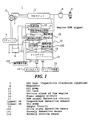
- FIG. 1 is a block diagram of the control for a two-cycle engine.
- the two-cycle engine 1 is equipped with a flywheel magnet 2.
- the electrical generation by this flywheel magnet 2 serves as drive power source for a CDI unit 3 (Capacitive Discharge Ignition), and as a drive power source, through the regulator 4, for the lubricating-oil supply apparatus 10.
- the battery 6 is also charged through the regulator 4.
- the flywheel magnet 2 is equipped with a pulse coil 7.
- the pulse signals from the pulse coil 7 are used by the CDI unit 3 to emit the engine RPM signal.
- the ignition coil 8 provides spark to the spark plugs 9 based upon the engine RPM signal.
- the lubricating-oil supply apparatus 10 comprises a unitized a control unit 11, electromagnetic solenoid 12 and oil pump 13; the driving of the oil pump 13 supplies lubricating oil from the oil tank 14 to a number of areas 15 of the engine. Electrical power to the electromagnetic solenoid 12 provides the drive for the oil pump 13.
- the control unit 11 is equipped with a power circuit 16, an RPM signal detection circuit 17, a temperature detection sensor 18, CPU 19, and an output circuit 20.
- the power circuit 16 applies the drive power to the control unit 11.
- the RPM detection circuit 17, detects the engine's RPM from the CDI unit 3 and sends it to the CPU 19. At the CPU 19, the pulse cycles are measured to detect the engine's RPM.
- the CPU 19 also computes the lubricating-oil requirement based upon the engine RPM. This lubricating-oil requirement can be determined by experimentation, etc., for various engine RPM ranges, and then that requirement can be read from a two-dimensional map of the engine RPM and lubricating-oil requirements. For example, the lubricating-oil requirement (m1) can be computed for each revolution for the engine RPM levels, for example, for 1500, 3000, 4000, 5000, 6000, 10000....
- the ON time for the electromagnetic solenoid 12 can also be set by the CPU 19 based upon such factors as the type of lubricating oil, temperature, etc. For example, after detecting the temperature of the lubricating oil, the ON time can be set using a two-dimensional map based on temperature. The ON time (ms) can thus be determined from the temperature (°C) of the lubricating oil, for example, for temperatures of -40, -20, 0, 20, 40, 60....
- the lubricating-oil supply apparatus 10 is equipped with a drive state detection means 100 that detects the drive state of the electromagnetic solenoid 12 and with an anomaly detection means 101 that detects anomalies by comparing the ON/OFF output timing that drives the electromagnetic solenoid 12 with the drive state detection timing of the electromagnetic solenoid 12.
- the electromagnetic solenoid 12 is used for the electrical drive of the oil pump 13; it makes it possible to supply precise quantities of lubricating oil that match the engine's requirements. Furthermore, comparing the ON/OFF output timing that drives the electromagnetic solenoid 12 with the drive state detection timing of the electromagnetic solenoid 12 makes it possible to use electronic controls to reliably detect any anomalies in that drive system.
- the lubricating-oil supply apparatus 10 is equipped with an anomaly warning means that provides warning of anomalies when they are detected.
- Such warning may be, for example, notification of the user by means of a blinking light, or the transmission of that warning to an ignition control unit which controls the ignition to prevent the engine RPM from rising above a certain level, thereby preventing the seizing of the engine.
- FIG. 2 is a sectional view of the lubricating-oil supply apparatus.
- the case 30 of the lubricating-oil supply apparatus 10 contains a unitized control unit 11, electromagnetic solenoid 12, and oil pump 13.
- the baseplate 31 of the control unit 11 is supported between the housing 32 and the dividing wall member 33.
- a thermistor is a temperature detection sensor 18.
- the baseplate 31 connects with a waterproof coupler 34, which makes connections with a battery 6, regulator 4, and CDI unit 3.
- the plunger is movably supported on the support member 35 for the electromagnetic solenoid 12.
- One end of the plunger 36 is connected to the pump rod 37 of the oil pump 13, while the other end is attached to the motive member 38.
- the pump rod 37 is movably mounted in the pump unit 39, and the force of a spring 40 biases a lubricating-oil passage in the open direction and keeps the motive member 38 in contact with the dividing wall member 33. With the motive member 38 in contact with the dividing wall member 33, there is a distance D between the motive member 38 and the support member 35; that distance defines the operational excursion of the plunger 36.
- a coil 41 encompasses the support member 35 of the electromagnetic solenoid 12 and the motive member 38.
- This coil 41 is connected by a wire 42 to the baseplate 31.
- the plunger 36 moves from the position shown in Figure 2 toward the closed direction a of the of the lubricating-oil passage, and the motive member 38 moves to come in contact with the support member 35.
- the spring 40 causes the plunger 36 to move toward the open direction b of the lubricating-oil passage, thereby returning to the position shown in Figure 2. Repetition of this action causes pumping the lubricating oil.
- a housing 60, 61 is fitted onto both sides of the pump unit 29 of the oil pump 13.
- the intake passage 39b is connected with the pump outlet passage 39c by a connecting passage 39d.
- the lubricating passage 39a and the intake passage 39b are connected through a filter 62 with the tank-side passage 60a of the housing 60; the pump outlet passage 39c is connected to the engine-side passage 60b of the housing.
- the lubricating-oil passage 39a conducts the lubricating oil toward the spring side to provide lubrication to the sliding areas of the spring 40 and the pump rod 37.
- the intake passage 39b is opened and closed by a ball valve 63, and the connecting passage 39d is also opened and closed by a ball valve 64.
- the ball valve 63 is biased in the closed direction c by a spring 65 disposed between it and the pump rod 37.
- the spring 40 causes the pump rod 37 to move in the opening direction b , which causes the ball valve 36 to move in the opening direction d for the intake passage 39b, thereby opening that intake passage 39b to the intake of lubricating oil.
- the oil pump 13 is electrically driven based on the engine's operating state through the electronic ON/OFF control of the electromagnetic solenoid 12. This allows the high precision supply of lubricating oil to the engine according to its requirements.
- control unit 11 determines the engine's RPM, computes the amount of lubricating oil required based upon the engine RPM, and controls the electromagnetic solenoid 12 by computing a pumping frequency for the solenoid.
- the ON time for the electromagnetic solenoid 12 can be set according to the lubricating-oil conditions, such as the type of lubricating oil, the temperature and other oil conditions. This feature makes it possible to supply highly accurate amounts of lubricating oil to various areas 15 of the engine.
- the ON time for the electromagnetic solenoid 12 can be computed from a two-dimensional map based on the temperature of the lubricating oil. Since the viscosity of the lubricating oil increases with lower temperatures, if the ON time were to remain constant, it would not be possible to pump the required amounts of lubricating oil when the oil viscosity was higher due to lower temperatures; the resulting reduced output of lubricating oil could cause the engine to seize. However, by varying the ON time according to the temperature of the lubricating oil, it becomes possible to reliably prevent engine seizing.
- the electromagnetic solenoid 12 and the oil pump 13 of the lubricating-oil supply apparatus 10 there is a correlation between the temperature upon the baseplate 31 and the oil temperature.
- the temperature detection sensor 18 may be mounted on the baseplate 31 to avoid the need for wire routing, which provides a cost advantage.
- the drive state detection means 100 for the lubricating-oil supply apparatus 10 is a detection sensor 120 that detects the magnetic field generated when the electromagnetic solenoid 12 is turned ON.
- This detection sensor 120 can employ a Hall IC or the like as a magnetic sensor.
- the detection sensor 120 is mounted opposite the electro-magnetic solenoid 12 on the baseplate 31; it detects the magnetic field generated when the electromagnetic solenoid 12 is turned ON and then sends a signal to the CPU 19.
- the anomaly detection means 101 of the CPU 19 detects anomalies by comparing the ON/OFF output timing that drives the electromagnetic solenoid 12 with the drive state detection timing of the electromagnetic solenoid 12. The detection of the magnetic field when current is applied to the electromagnetic solenoid 12 makes it possible to detect broken wires in the electromagnetic solenoid 12.
- Figure 3 shows another embodiment of the lubricating-oil supply apparatus.
- the drive state detection means of the lubricating-oil supply apparatus 10 is a detection sensor 130 that detects the operation of the plunger 36 of the electromagnetic solenoid 12.
- a magnetic sensor such as a Hall IC may be used as this detection sensor 130.
- This detection sensor 130 may be mounted on the baseplate 31 in a position opposite a magnetic member 131 that is mounted on the end of the plunger 36. It then detects the generated magnetic field that accompanies the operation of the plunger 36 and sends that information to the CPU 19.
- the position of the detection sensor 130 is such that it lies a certain distance W from the electromagnetic solenoid 12; the preservation of this distance W prevents any effects from the magnetic field generated by the electromagnetic solenoid 12 from interfering with the detection sensor 130.
- a magnetic shield can be used for the dividing wall member 33, which further assures that the detection sensor 130 remains unaffected by the magnetic field from the electromagnetic solenoid 12.
- the anomaly detection means 101 of the CPU 19 detects anomalies by comparing the ON/OFF timing that drives the electromagnetic solenoid 12 with the operation detection timing; this makes it possible to detect anomalies in the drive system by detecting the movement of the plunger 36 of the electromagnetic solenoid 12.
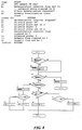
- Figure 4 is a main process flow chart for the lubricating-oil supply apparatus.
- the engine RPM is computed on the basis of engine RPM signal from the CDI unit (step b1).
- the lubricating-oil requirement is computed based on a two-dimensional map with the engine RPM (step c1), and the lubricating-oil temperature is detected by the temperature detection sensor 18 (step d1).
- the ON time for the electromagnetic solenoid 12 is then set based upon the detection of the lubricating-oil temperature using a two-dimensional map with the oil temperature (step e1). Conversion is then made for the ON/OFF pump cycles for the electromagnetic solenoid 12 (step f1). Drive control is then exercised over the turning ON and OFF of the electromagnetic solenoid 12 (step g1).
- step h1 Amid this ON/OFF drive of the electromagnetic solenoid 12, detection of any anomalies in the drive system is performed by electronic control which compares the ON/OFF output timing that drives the electromagnetic solenoid 12 with the drive state detection timing for the electromagnetic solenoid 12 (step h1). If an anomaly is detected, control is exercised to provide an anomaly warning (step i1) via an anomaly warning means 102.
- FIG. 5 is a flow chart for the ON/OFF pump cycle computation for the electromagnetic solenoid.
- the pumping volume from one cycle of operation by the plunger 36 is mechanically determined.
- the pump cycles and the ON time can be used to drive a timer that performs the ON/OFF control of the electromagnetic solenoid 12.
- the time required for 1 revolution of the engine is 60 ⁇ engine RPM, so multiplication by n yields the pump cycle time (seconds).
- Figure 7 is a flow chart showing the ON/OFF control of the electromagnetic solenoid.
- a determination is made of whether or not the electromagnetic solenoid is currently ON (step a2) and if it is ON, a determination is made of whether or not the ON time setting has elapsed (step b2). If the ON time has not elapsed, the program flow returns, if the ON time has elapsed, the electromagnetic solenoid 12 is turned OFF and there is a return (step c2).
- step a2 If at step a2 the electromagnetic solenoid 12 is currently OFF, a computation is made of the OFF time by subtracting the ON time from the pump cycle (step d2) and then a determination is made as to whether the OFF time as elapsed (step e2). If the OFF time has not elapsed, the program returns, if it has elapsed, the timer that performs the ON/OFF control is released (step f2) and then the electromagnetic solenoid 12 returns to ON (step g2).
- Figure 8 is a flow chart of anomaly detection for the case when a solenoid wire breakage is detected.
- Figure 9 is a flow chart of anomaly detection when there is a plunger operation anomaly.
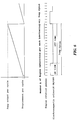
- Figure 10 is a timing chart of the detection of an anomaly.
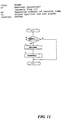
- Figure 11 is a flow chart of anomaly warning control
- step a3 when there is a solenoid wire break detection, a determination is made as to whether or not the output from the CPU 19 is currently ON (step a3); if it is ON, the anomaly determination timer is set, the anomaly determinating interval flag is set to 1, and the electromagnetic solenoid state determination flag is cleared to 0 (step b3). Then, a determination is made of whether or not the anomaly determination interval is in effect (step c3); when OFF in step a3, the program moves to step c3, having determined that the anomaly determination interval is not in effect.
- the anomaly determination timer is cleared and there is a return (to step d3).
- the electromagnetic solenoid state determination flag is set to 1 and the program returns (step g3). If the electromagnetic solenoid 12 is OFF, a determination is made as to whether or not the electromagnetic solenoid state determination flag is 1 (step h3), if the determination flag is not 1, the program returns, if the determination flag is 1, the electromagnetic solenoid state determination flag is set to 2 and the program returns (step i3).
- step j3 If the anomaly determination interval has elapsed in step e3, the anomaly determination interval flag is cleared to 0 (step j3), a determination is made of whether or not the electromagnetic solenoid state determination flag is 2 (step k3); if the determination flag is 2, the electromagnetic solenoid is normal, the anomaly flag is cleared to 0, and the program returns (step l3). In step k3, if the electromagnetic solenoid state determination flag is not 2, the electromagnetic solenoid is abnormal, the anomaly flag is set to 1, and the program returns (step m3).
- step a4 when a plunger operational anomaly is detected, a determination is made as to whether or not the output from the CPU 19 is currently ON (step a4), if ON, the anomaly determination timer is set, the anomaly determination interval flag is set to 1, and the plunger state determination flag is cleared to 0 (step b4). A determination is then made as to whether or not the anomaly determination interval has elapsed (step c4); if OFF in step a4, the program proceeds to step c4 and determines whether or not the anomaly determination interval is in effect.
- the anomaly determination timer is cleared and the program returns (step d4). If within the anomaly determination interval, a determination is made as to whether or not the anomaly determination interval has elapsed (step e4), if it has not elapsed, a determination is made as to whether or not the plunger position is ON (step f4).
- the plunger state determination flag is set to 1 and the program returns (step g4). If the plunger position is OFF, a determination is made as to whether or not the plunger state determination flag is 1 (step h4), if the determination flag is not 1, the program returns; if the determination is 1, the plunger state determination flag is set to 2 and the program returns (step i4).
- step e4 the anomaly determination interval flag is cleared to 0 (step j4) and a determination is made of whether or not the plunger state determination flag is 2 (step k4). If the determination flag is 2, the plunger 36 is normal, the anomaly flag is cleared to 0, and the program returns (step l4). If in step k4 a determination is made that the plunger state determination flag is not 2, then the plunger 36 operated abnormally, the anomaly flag is set to 1, and the program returns (step m4).
- step a5 when an anomaly is detected, a determination is made as to whether the electromagnetic solenoid 12 is abnormal by checking whether the anomaly flag is 1 (step a5), if not abnormal, the program returns. If it is abnormal, control is exercised to blink the warning lamp (step b5), an engine ignition cutoff control signal is emitted, and the program returns (step c5). If there is an anomaly, it is also possible to exercise either control to cause the warning lamp to blink in step b5, or to cause a control signal to cut the ignition as in step c5.
- the invention employs an electrically driven oil pump which makes it possible to accurately supply the amounts of lubricating oil required by the engine. Further, by comparing the ON/OFF output timing that drives the electromagnetic solenoid with the timing of the electromagnetic solenoid drive state detector, it is further possible to reliably detect anomalies in the drive system using electronic controls.
- the system detects when current is applied to the electromagnetic solenoid, thereby making it possible to detect broken wires in the electromagentic solenoid.
- the apparatus makes it possible to detect anomalies of the drive system.
- the apparatus performs anomaly warnings upon detection of an anomaly.
- anomaly warning may consist, for example of a notification to the user of the anomaly by causing a warning lamp to flash, or it can transmit the anomaly warning to control the ignition system, or cut the ignition at times when the engine RPM exceeds a certain level in order to prevent engine seizing.
Landscapes
- Engineering & Computer Science (AREA)
- Mechanical Engineering (AREA)
- General Engineering & Computer Science (AREA)
- Lubrication Of Internal Combustion Engines (AREA)
- Lubrication Details And Ventilation Of Internal Combustion Engines (AREA)
Applications Claiming Priority (2)
| Application Number | Priority Date | Filing Date | Title |
|---|---|---|---|
| JP8236539A JPH1082310A (ja) | 1996-09-06 | 1996-09-06 | 2サイクルエンジンの潤滑油供給装置 |
| JP236539/96 | 1996-09-06 |
Publications (2)
| Publication Number | Publication Date |
|---|---|
| EP0828062A2 true EP0828062A2 (de) | 1998-03-11 |
| EP0828062A3 EP0828062A3 (de) | 1998-11-25 |
Family
ID=17002178
Family Applications (1)
| Application Number | Title | Priority Date | Filing Date |
|---|---|---|---|
| EP97115468A Ceased EP0828062A3 (de) | 1996-09-06 | 1997-09-05 | Schmierölversorgungsanlage für Zweitaktbrennkraftmaschine |
Country Status (6)
| Country | Link |
|---|---|
| US (1) | US5934242A (de) |
| EP (1) | EP0828062A3 (de) |
| JP (1) | JPH1082310A (de) |
| CN (1) | CN1096539C (de) |
| ID (1) | ID20404A (de) |
| TW (1) | TW360740B (de) |
Cited By (1)
| Publication number | Priority date | Publication date | Assignee | Title |
|---|---|---|---|---|
| US12000743B2 (en) | 2019-10-22 | 2024-06-04 | Textron Systems Corporation | Safeguarding equipment based on detection of reduced cyclical pump performance |
Families Citing this family (12)
| Publication number | Priority date | Publication date | Assignee | Title |
|---|---|---|---|---|
| JP3260705B2 (ja) * | 1998-10-19 | 2002-02-25 | 株式会社テネックス | エアクリーナ等の空気処理用機器におけるダクトの取付装置 |
| JP2003336512A (ja) * | 2002-05-20 | 2003-11-28 | Yamaha Marine Co Ltd | 2サイクルエンジンの潤滑油ポンプ制御方法 |
| JP2004052724A (ja) * | 2002-07-23 | 2004-02-19 | Yamaha Marine Co Ltd | エンジンにおける潤滑油供給装置、およびこの装置を用いた船外機 |
| JP2004156487A (ja) * | 2002-11-05 | 2004-06-03 | Yamaha Marine Co Ltd | エンジンにおける液体供給制御装置 |
| FI114735B (fi) * | 2003-07-03 | 2004-12-15 | Crane John Safematic Oy | Sovitelma keskusvoitelujärjestelmän yhteydessä |
| SE531604C2 (sv) * | 2007-10-17 | 2009-06-02 | Atlas Copco Rock Drills Ab | Anordning och metod för att styra tillförsel av smörjmedel vid ett arbetsfordon |
| PL2250350T3 (pl) * | 2008-02-08 | 2015-02-27 | Flashlube Pty Ltd | System doprowadzania środka smarnego do silników spalinowych wewnętrznego spalania |
| CA2762251C (en) * | 2009-09-30 | 2015-12-01 | Bombardier Recreational Products Inc. | Electronic oil pump |
| JP6052987B2 (ja) * | 2012-12-26 | 2016-12-27 | アスモ株式会社 | 電動ポンプ |
| CN105065085B (zh) * | 2015-07-31 | 2017-11-10 | 吉林大学 | 一种多传感器信息融合的机油品质在线监测系统及其方法 |
| JP6502811B2 (ja) * | 2015-09-18 | 2019-04-17 | アイシン精機株式会社 | 電動ポンプ |
| CN106567960B (zh) * | 2016-10-17 | 2019-07-05 | 潍柴动力股份有限公司 | 一种电磁阀的控制方法和系统 |
Family Cites Families (9)
| Publication number | Priority date | Publication date | Assignee | Title |
|---|---|---|---|---|
| US4445470A (en) * | 1982-12-27 | 1984-05-01 | Brunswick Corporation | Oil injection warning system |
| US4774918A (en) * | 1986-01-24 | 1988-10-04 | Mazda Motor Corporation | Engine lubricating system |
| DE3735019A1 (de) * | 1986-10-14 | 1988-05-19 | Orbital Eng Pty | Schmiersystem fuer eine verbrennungsmaschine und pumpe hierfuer |
| ES2094841T3 (es) * | 1991-04-12 | 1997-02-01 | Yamaha Motor Co Ltd | Metodo para lubricar un motor de combustion interna de dos tiempos y sistema de suministrar aceite lubricante. |
| US5390635A (en) * | 1992-03-16 | 1995-02-21 | Yamaha Hatsudoki Kabushiki Kaisha | Lubricating oil supplying system for engine |
| DE69408055T2 (de) * | 1993-04-02 | 1998-05-07 | Yamaha Motor Co Ltd | Verfahren und Einrichtung zur Schmierung einer Brennkraftmaschine |
| JPH08135462A (ja) * | 1994-11-09 | 1996-05-28 | Yamaha Motor Co Ltd | 縦型エンジン |
| DE19581602T1 (de) * | 1994-03-29 | 1997-04-17 | Orbital Eng Australia | Zweiteilige Pumpe |
| US5662081A (en) * | 1995-07-24 | 1997-09-02 | Outboard Marine Corporation | Oil supply failure detection circuit |
-
1996
- 1996-09-06 JP JP8236539A patent/JPH1082310A/ja active Pending
-
1997
- 1997-08-14 TW TW086111676A patent/TW360740B/zh active
- 1997-09-01 ID IDP973044A patent/ID20404A/id unknown
- 1997-09-05 CN CN97117942A patent/CN1096539C/zh not_active Expired - Fee Related
- 1997-09-05 EP EP97115468A patent/EP0828062A3/de not_active Ceased
- 1997-09-08 US US08/924,901 patent/US5934242A/en not_active Expired - Fee Related
Non-Patent Citations (1)
| Title |
|---|
| None |
Cited By (1)
| Publication number | Priority date | Publication date | Assignee | Title |
|---|---|---|---|---|
| US12000743B2 (en) | 2019-10-22 | 2024-06-04 | Textron Systems Corporation | Safeguarding equipment based on detection of reduced cyclical pump performance |
Also Published As
| Publication number | Publication date |
|---|---|
| CN1096539C (zh) | 2002-12-18 |
| TW360740B (en) | 1999-06-11 |
| CN1182167A (zh) | 1998-05-20 |
| EP0828062A3 (de) | 1998-11-25 |
| JPH1082310A (ja) | 1998-03-31 |
| ID20404A (id) | 1998-12-10 |
| US5934242A (en) | 1999-08-10 |
Similar Documents
| Publication | Publication Date | Title |
|---|---|---|
| EP0831208A2 (de) | Schmierölversorgungsanlage | |
| WO2008016916A2 (en) | Small engine operation components | |
| JP3822662B2 (ja) | エンジンのデマンド燃料供給装置 | |
| CN101294507B (zh) | 发动机换油检测系统和方法 | |
| US4562801A (en) | Engine control system for marine propulsion device | |
| US20210033036A1 (en) | Engine kill switch and control assembly | |
| RU93058469A (ru) | Способ управления работой топливной системы, топливная система для двигателя внутреннего сгорания | |
| US10590878B2 (en) | Control strategy for automatic shutdown of engine | |
| JPH1082310A (ja) | 2サイクルエンジンの潤滑油供給装置 | |
| US20180283293A1 (en) | Control strategy for automatic shutdown of engine | |
| US7007656B2 (en) | Lubrication supply control system | |
| CN108291487B (zh) | 节流触发器促动的节流部位置传感器和发动机控制模块 | |
| US4995357A (en) | Engine shut-off circuit | |
| JP2008267866A (ja) | 粘度検出装置 | |
| US8770172B2 (en) | Fuel shortage detecting apparatus for general-purpose engine | |
| CA1244108A (en) | Low liquid level sensing and warning circuit | |
| US6761142B2 (en) | Oil pressure control for an outboard motor | |
| US4501140A (en) | Fuel injection rate deducing system for a diesel engine | |
| US7150249B2 (en) | Lubrication system for two-cycle engine | |
| JPH1037730A (ja) | 2サイクルエンジンの潤滑油供給装置 | |
| US5662081A (en) | Oil supply failure detection circuit | |
| CN110242453B (zh) | 一种用于呼吸器出气口的自动除冰装置 | |
| US7503209B2 (en) | Timing device for internal combustion engine | |
| US20190017456A1 (en) | Engine operator initiated self-adjustment system | |
| JP2003343231A (ja) | 2サイクルエンジンのオイル制御装置 |
Legal Events
| Date | Code | Title | Description |
|---|---|---|---|
| PUAI | Public reference made under article 153(3) epc to a published international application that has entered the european phase |
Free format text: ORIGINAL CODE: 0009012 |
|
| AK | Designated contracting states |
Kind code of ref document: A2 Designated state(s): DE FR IT |
|
| AX | Request for extension of the european patent |
Free format text: AL;LT;LV;RO;SI |
|
| PUAL | Search report despatched |
Free format text: ORIGINAL CODE: 0009013 |
|
| AK | Designated contracting states |
Kind code of ref document: A3 Designated state(s): AT BE CH DE DK ES FI FR GB GR IE IT LI LU MC NL PT SE |
|
| AX | Request for extension of the european patent |
Free format text: AL;LT;LV;RO;SI |
|
| 17P | Request for examination filed |
Effective date: 19990521 |
|
| AKX | Designation fees paid |
Free format text: DE FR IT |
|
| 17Q | First examination report despatched |
Effective date: 20010612 |
|
| GRAG | Despatch of communication of intention to grant |
Free format text: ORIGINAL CODE: EPIDOS AGRA |
|
| STAA | Information on the status of an ep patent application or granted ep patent |
Free format text: STATUS: THE APPLICATION HAS BEEN REFUSED |
|
| 18R | Application refused |
Effective date: 20020930 |