EP0826080B1 - Cut-pile mechanism and process - Google Patents
Cut-pile mechanism and process Download PDFInfo
- Publication number
- EP0826080B1 EP0826080B1 EP96919787A EP96919787A EP0826080B1 EP 0826080 B1 EP0826080 B1 EP 0826080B1 EP 96919787 A EP96919787 A EP 96919787A EP 96919787 A EP96919787 A EP 96919787A EP 0826080 B1 EP0826080 B1 EP 0826080B1
- Authority
- EP
- European Patent Office
- Prior art keywords
- pile
- elements
- cutting
- loops
- contact
- Prior art date
- Legal status (The legal status is an assumption and is not a legal conclusion. Google has not performed a legal analysis and makes no representation as to the accuracy of the status listed.)
- Expired - Lifetime
Links
- 238000000034 method Methods 0.000 title description 15
- 230000008569 process Effects 0.000 title description 5
- 230000007246 mechanism Effects 0.000 title description 3
- 238000005520 cutting process Methods 0.000 claims abstract description 217
- 239000004744 fabric Substances 0.000 claims abstract description 28
- 239000000835 fiber Substances 0.000 claims abstract description 19
- 239000004753 textile Substances 0.000 claims abstract description 17
- 230000015572 biosynthetic process Effects 0.000 claims description 2
- 238000009732 tufting Methods 0.000 abstract description 10
- 238000009940 knitting Methods 0.000 description 18
- 238000004519 manufacturing process Methods 0.000 description 17
- 239000000463 material Substances 0.000 description 7
- 230000009471 action Effects 0.000 description 6
- 230000006835 compression Effects 0.000 description 3
- 238000007906 compression Methods 0.000 description 3
- 238000007596 consolidation process Methods 0.000 description 3
- 238000010276 construction Methods 0.000 description 2
- 230000000694 effects Effects 0.000 description 2
- 238000003825 pressing Methods 0.000 description 2
- 230000009467 reduction Effects 0.000 description 2
- 238000000926 separation method Methods 0.000 description 2
- 238000005299 abrasion Methods 0.000 description 1
- 230000001154 acute effect Effects 0.000 description 1
- 230000008901 benefit Effects 0.000 description 1
- 238000007688 edging Methods 0.000 description 1
- 238000009950 felting Methods 0.000 description 1
- 238000010348 incorporation Methods 0.000 description 1
- 238000010030 laminating Methods 0.000 description 1
- 238000012986 modification Methods 0.000 description 1
- 230000004048 modification Effects 0.000 description 1
- 238000012545 processing Methods 0.000 description 1
- 230000002035 prolonged effect Effects 0.000 description 1
- 230000000717 retained effect Effects 0.000 description 1
- 230000002441 reversible effect Effects 0.000 description 1
- 238000010008 shearing Methods 0.000 description 1
Images



Classifications
-
- D—TEXTILES; PAPER
- D04—BRAIDING; LACE-MAKING; KNITTING; TRIMMINGS; NON-WOVEN FABRICS
- D04B—KNITTING
- D04B9/00—Circular knitting machines with independently-movable needles
- D04B9/12—Circular knitting machines with independently-movable needles with provision for incorporating pile threads
-
- D—TEXTILES; PAPER
- D04—BRAIDING; LACE-MAKING; KNITTING; TRIMMINGS; NON-WOVEN FABRICS
- D04B—KNITTING
- D04B23/00—Flat warp knitting machines
- D04B23/08—Flat warp knitting machines with provision for incorporating pile threads
Definitions
- a cutting element is associated with each pile element or sinker.
- the cutting element is mounted together with or separately from the pile element and is actuated relatively thereto for severing pile loops.
- the cutting edge of the cutting element is disposed at an angle, the opening angle, with the cutting edge of the pile element, such that both edges are disposed in a V-like configuration prior to the cutting movement which brings them together like a pair of scissors.
- the cutting action has been performed with an inadequate lateral compression of the cutting edges. Therefore, it is easily possible for the cutting edges of the cutting and pile elements to be deflected by the unsevered pile loops encircling the pile elements. This may happen particularly if the pile loops are tightly enclosed around the pile elements and if the pile yarn is, furthermore, a material having high tenacity and/or abrasion resistance.
- the cutting elements on tufting machines were mounted separately from the pile elements and, from the side of the active flank of the pile element, i.e. the flank comprising the cutting edge, were arranged to resiliently contact the latter at a relative inclination, the contact angle.
- the nibs of the cutting elements contact the pile elements as a result of the inclined arrangement of the cutting elements, a risk is created of obstructing contact between the cutting edges of the cutting elements and the cooperating cutting edges of the pile elements, so that the flanks of the cutting elements are also arranged to be inclined with respect to the pile elements. Therefore, prior to the cutting movement, the cutting edges of pile elements and cutting elements have a corresponding overlapping configuration, referenced as a cutting angle, and the elements have only one point of contact. This point of contact shifts during the cutting movement from the lower ends of the cutting edges across their entire length to their upper ends and in the process deflects the overlapping part of the cutting elements from the pile elements. The gap created thereby is to prevent pinching of severed pile loops and separation of the cutting edges thereby.
- this cutting angle between the two elements is of particular importance.
- the cutting angle must be dimensioned to sufficiently Separate the elements after the cutting point an this to avoid pinching of pile loops.
- the cutting movement is performed by a relative movement of the mounting bar of the cutting elements in parallel with the flanks of the pile elements.
- a constant contact pressure between the elements is ensured exclusively by a sufficiently wide cutting angle in combination with an acute angle under which the cutting element is pressed against the pile element during the cutting motion.
- the contact angle of the cutting element to the pile element Due to the contact angle of the cutting element to the pile element, the required contact pressure for severing the pile loops is obtained, whereby the cutting elements are resiliently bent. Therefore, the contact angle is smaller in the area of the cutting edges than in the mounting area as a function of the material thickness.
- the thickness of the cutting elements is determined by the gauge and by the thickness of the pile elements.
- the pile elements must be of a sufficient size that the cutting angle cannot be reduced or neutralized by a deflection of the pile elements as a result of pressurized contact with the cutting elements.
- the maximum thickness of the cutting elements is, therefore, determined by the gauge and the thickness of the pile elements under consideration of the contact angle and the cutting angle.
- the inactive flanks of the pile elements opposite the cutting edges are partially bevelled to obtain the required space in between the pile elements. Adequate strength of the cutting elements is necessary to avoid torsional forces in the transverse axis of the cutting elements whereby also the cutting angle of the cutting edges may be reduced or neutralized, respectively, and the cutting elements would contact the pile elements with their front ends.
- the cutting elements are arranged to extend from a mounting point located on the side of the inactive flanks of the pile elements, i.e. the side opposite the cutting edge thereof, toward and into contact with the active flanks of the pile elements, i.e. the side flank having the cutting edge.
- the novel disposition of the pile and cutting elements relative to each other requires less space thereby enabling construction of very fine gauge machines with small distances between pile elements and cutting elements.
- the reduced cutting angle need not be compensated by increased contact pressure, especially the cutting elements can be dimensioned with a view to better stability.
- the lateral pressure applied by the cutting elements to the pile elements is reduced, and more uniform contact pressure is obtained during the severing action so that undesirable lateral movement or distortion of the elements are greatly lessened or prevented.
- the technical progress realized by this invention makes it possible to adopt the pile forming and cutting device into the manufacturing process of velour-like fabrics according to a variety of methods.
- the invention is generally implemented on textile machines on which yarns or fibers are drawn out to form pile loops. This is performed by the pile forming surfaces at the free ends of the pile elements.
- the pile elements include cutting edges forming a V-shaped mouth with the cutting edges of separate cutting elements prior to any scissor-like cutting movement that will sever the held or retained pile loops.
- FIG. 1 A corresponding arrangement of pile elements and cutting elements on circular knitting machines is shown in the two embodiments of Figs. 1 to 5. These are based on a circular knitting machine referred to in EP-A2-0 082 538 and US-A2-4,592,212, respectively.
- pile fabrics by needles N arranged in a dial R and pile elements 1 arranged in the cylinder Z is furthermore known from a multitude of publications. Accordingly, pile yarns are drawn out into pile loops H1 (Fig. 1) over pile forming ledges 1a during the knitting step and remain on the pile elements during the subsequent knitting actions thereby sliding downwardly on the stems of the pile elements, by the take-down action, to the cutting zone constituted by the pile elements 1 and the cutting elements 2.
- Cutting zones are formed on the pile elements 1 as a continuation of the pile forming ledges 1a, by grinding the lateral cutting flanks of these pile elements at an angle ⁇ 1 to form cooperating cutting edges 1c (Fig. 2).
- Sharp cutting edges 2c are correspondingly ground at angle ⁇ 2 on the cutting elements 2, specifically on their cutting flanks, so that cutting edges 2c will contact the pile elements 1 and cutting edges 1c. Due to an inclined positioning of the cutting edges 2c relative to the substantially vertical cooperating cutting edges 1c of the pile elements 1, the facing cutting edges 1c and 2c form a vertical V-like mouth or opening as to be seen in Fig. 1 (opening angle).
- the cutting elements 2 are shifted toward pile elements 1 thereby closing the V-like opening between cutting edges 1c and 2c.
- the control mechanism for the cutting elements comprises, as is usual, cams which act on butts of the cutting elements for the radial movements of the cutting elements.
- Sufficient lateral contact pressure between the cutting elements 2 and the pile elements 1, to assure severing of the pile loops, is preferably realized by separately mounting the cutting elements 2 and the pile elements 1 (Figs. 1 and 2). In a circular knitting machine this is preferably effected by arranging the cutting elements 2 in a sinker ring P which is rotatably adjustable in a lateral direction with respect to cylinder Z which supports the pile elements 1.
- the cutting elements 2 are located in a sinker ring P being adjustable in a lateral direction relative to the cylinder Z into a condition in which the flanks of the cutting elements 2, subsequent to contacting the cutting edges 1c of the pile elements 1, are deflecting at an angle ⁇ (Fig. 2) from the flanks of the pile elements 1 and elastically pressed thereagainst.
- ⁇ Fig. 2
- a sufficient angle a of preferably between 2° and 8° ensures that this gap is also preserved if a pile element 1 insignificantly deflects laterally or if the flank of a cutting element 2 is insignificantly distorted. In any case, a planar contact between the respective flanks of the elements is thereby prevented and the effect of concave grinding in a pair of scissors is obtained.
- the gap formed between the flanks of the elements according to the invention following cutting is obtained by the inclined disposition of the cutting elements 2 relative to the pile elements 1. Therefore, the vertical inclination of the flanks of the cutting elements 2 at an angle ⁇ relative to the flanks of the pile elements 1 (cutting angle) according to Fig. 3 can be reduced.
- This arrangement increases durability of the cutting edges and reduces stop times of the machines to replace blunted elements along with a reduced consumption of pile and cutting elements.
- a further advantage of the arrangement or relative position of the cutting elements 2, according to the invention resides in the fact that the laterally shifted disposition of the mounting of the cutting elements relative to the contact surface on the pile elements is smaller than in the known proposals since the pressing or contact angle ⁇ required at the point of contact between the elements is realized with a reduced angle near the mounting (sinker ring) or an equivalent solution.
- the cutting elements 2 Preferably, permanent contact exists between the cutting elements 2 with the pile elements 1 (other than during the severing action) through a nib 2n shown in Figs. 1 and 2. If that part of the pile elements 1 below the cutting edge 1c nevertheless projects between the cutting elements 2, the relevant portions ls, shown Figs. 1, 2 and 3, must have a greater bevel than at the pressurized contact angle a. Therefore, the elements contact each other exclusively on the cutting edge 1c or in the continuation 1s thereof. Further, the vertical movement of the pile elements 1 on the cutting element 2 produces a self-sharpening effect on the cutting edge 1c.
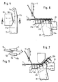
- Figs. 4 and 5 demonstrate an arrangement of pile elements 11, that include pile forming ledges 11a and cooperating cutting edges 11c, and of cutting elements 12 that have cooperating cutting edges 12c. Permanent contact between the elements is ensured by the guiding surface 11s of the pile element 11 which projects radially outwardly beyond the cutting edges 11c and has a bevel surface that is angled in a correspondingly greater amount than the pressing or contact angle ⁇ .
- Such a solution is largely reserved for machines having coarser gauges.
- the embodiment according to Figs. 1 to 3 is preferred since it largely avoids the bevel-edging of pile elements.
- Figs. 6 and 7 illustrate the pile elements and cutting elements on a tufting machine for manufacturing velour fabrics.
- the elements are fixed in bars which are actuated in a well known manner.
- the needles S which are arranged in one row or have a staggered arrangement in two rows, penetrate through a ground or backing fabric T to thereby form loops which are engaged by pile forming ledges 21a or 31a of the respective pile elements 21 and 31.
- the previously formed pile loops slide along the stems of the pile elements, from left to right as seen in Figs. 6 and 7, toward a cutting zone.
- the cutting zone is formed between the cutting edges 21c and 22c of pile elements 21 and cutting elements 22, respectively, in Fig. 6, or by cutting edges 31c of pile elements 31 and cutting edges 32c of respective cutting elements 32 in Fig. 7.
- Fig. 6 demonstrates the traditional shape of pile elements 21 and cutting elements 22. To ensure the required inclined disposition of the cutting elements with respect to the pile elements 21, a bevel-edged guiding surface 21s is necessary according to the above description of Figs. 4 and 5.
- the cooperating cutting edge 31c, or its continuation on the pile element 31, extends across the cutting element 32.
- permanent contact with the pile element 31 is realized by at least one nib 32n (shown in dashed lines in the position prior to the cutting movement of cutting element 32).
- a suitable control of the ground fabric is provided. In accordance with the description of Figs. 1 to 3, finer gauges of tufting machines may thereby be obtained.
- This arrangement of pile elements and cutting elements for manufacturing cut-pile fabrics is also suitable for other textile machines.
- a possibility of manufacturing a cut-pile fabric on a warp-knitting machine or on a raschel machine is illustrated.
- the production of uncut loop fabrics on such machines is known.
- the bar 48 for the pile elements 41 has to be moved and controlled independently of the guide bars L1 to L4.
- the pile elements 41 may be arranged between the needles N1 either permanently, or only temporarily when the stitching process with the simultaneous forming of pile loops is performed.
- a lateral shifting of the pile elements 41 by their bar 48, together with the cutting elements 42 and their location in the bar 46 may be provided.
- At least one of the shown guide bars L1 to L4 places the pile yarns over the pile elements 41 so as to draw out pile loops.
- the pile loops will slide along the pile elements 41 toward and into a cutting zone of pile cutting edges 41c.
- cutting elements 42 are actuated towards the pile elements 41. This movement of the cutting edges 42c toward pile cutting edges 41c closes the space that existed therebetween (shown in dashed (lines). Due to the described arrangement of the cutting elements 42 with respect to the pile elements 41, as described for the previous embodiments, the pile loops that have slipped between the cutting edges 41c and 42c are severed.
- the actuation of cutting elements 42 to the pile elements 41 is performed, in analogy with the art known from tufting machines, to realize a permanent contact of the elements at least by a nib 42n.
- additional weft yarns may be inserted into the ground fabric.
- Pile elements 51 and cutting elements 52 are arranged in bars 58 and 56, respectively, and are actuated as described for the above described embodiment.
- a loose fleece F of staple fibers is supplied in the known manner for example from feeding sinkers 55 into the range of needles N2 which penetrate through the fleece F in their raising movement. Simultaneously, the pile elements 51 penetrate into the loose fleece F. After the binding yarns supplied by at least one guide bar L1-L4 have been lapped into the needle hooks, the needles N2 are retracted into the knockover position. Previously, the sinker bar 57 and the pile bar 58 with the pile elements 51 will have been retracted, whereby the pile element hooks 51h draw pile fibers onto the pile elements 51.
- the velour-like surface of severed pile fibers can also be realized on the stitch side of the fabric; a respective embodiment is shown in Fig. 10.
- a fiber fleece F is supplied into the machine and is penetrated by the pile elements 61 in a longitudinal direction. Between the pile elements 61 the needles N3 penetrate through the fleece F to engage the binding yarns from at least one guide bar L1 or L2, respectively, which consolidates the fleece. Simultaneously, lapping loops from pile fibers are formed over the pile elements 61 as shown in Fig. 10a. The stitch forming and the transportation of the looped fabric is supported by the hooked shape 61h of the pile elements 61.
- the lapped fiber loops on the pile elements 61 then slide along the pile element into the cutting zone where the loops are severed by the cutting edges 62c of cutting elements 62 and the cooperating cutting edges 61c of the pile elements 61 in accordance with the inclined relative arrangement of the invention.
- a reciprocating racking of the fleece may be carried out in conjunction with feeding of the fleece.
- Fig. 11 the consolidation of a fleece on a needle punch machine is shown in a simplified manner.
- the felting needles N4 are arranged in the movable bar 74 and penetrate the supplied fleece F, consolidating the fleece in cooperation with a perforated plate 73.
- the pile elements 71 are actuated at least into a part of the working area of the felt needles, picking up pile fibers to form pile loops thereof.
- the pile loops are transported into the cutting zone and severed there by a corresponding cutting movement of the cutting edges 72c of the cutting elements 72 which, according to the invention, are arranged at an inclination relative to the pile elements 71.
- the present embodiments illustrated and described herein exclusively demonstrate fundamental possibilities for manufacturing cut pile fabrics in accordance with different methods of producing textile fabrics. These methods are modifiable in accordance with the disposition of the elements forming or processing a ground fabric and pile loops.
- the invention preferably employs cutting elements 2, 12, 22, 32, 42, 52, 62 and 72 that are inclined relative to the pile elements 1, 11, 21, 31, 41, 51, 61 and 71 as illustrated and described according to Figs. 1 and 3, thereby forcibly separating the cutting elements from the pile elements at an angle ⁇ subsequent to the point of contact of the cutting edges.
Landscapes
- Engineering & Computer Science (AREA)
- Textile Engineering (AREA)
- Treatment Of Fiber Materials (AREA)
- Knitting Machines (AREA)
- Knitting Of Fabric (AREA)
- Disintegrating Or Milling (AREA)
- Scissors And Nippers (AREA)
Applications Claiming Priority (3)
| Application Number | Priority Date | Filing Date | Title |
|---|---|---|---|
| DE19518490 | 1995-05-19 | ||
| DE19518490A DE19518490A1 (de) | 1995-05-19 | 1995-05-19 | Polbildende Textilmaschine |
| PCT/EP1996/002145 WO1996036753A1 (en) | 1995-05-19 | 1996-05-17 | Cut-pile mechanism and process |
Publications (2)
| Publication Number | Publication Date |
|---|---|
| EP0826080A1 EP0826080A1 (en) | 1998-03-04 |
| EP0826080B1 true EP0826080B1 (en) | 1999-09-15 |
Family
ID=7762401
Family Applications (1)
| Application Number | Title | Priority Date | Filing Date |
|---|---|---|---|
| EP96919787A Expired - Lifetime EP0826080B1 (en) | 1995-05-19 | 1996-05-17 | Cut-pile mechanism and process |
Country Status (12)
| Country | Link |
|---|---|
| US (1) | US6094944A (it) |
| EP (1) | EP0826080B1 (it) |
| JP (1) | JPH11505300A (it) |
| KR (1) | KR19990014884A (it) |
| CN (1) | CN1068392C (it) |
| AT (1) | ATE184663T1 (it) |
| BR (1) | BR9608772A (it) |
| DE (2) | DE19518490A1 (it) |
| ES (1) | ES2138350T3 (it) |
| IN (1) | IN187461B (it) |
| TW (1) | TW387953B (it) |
| WO (1) | WO1996036753A1 (it) |
Families Citing this family (17)
| Publication number | Priority date | Publication date | Assignee | Title |
|---|---|---|---|---|
| DE19734331A1 (de) * | 1997-08-08 | 1999-02-11 | Maute & Renz Textil Gmbh | Verfahren zur Herstellung von Plüschware |
| KR20040023862A (ko) * | 2002-09-12 | 2004-03-20 | 페어차일드코리아반도체 주식회사 | 모터 구동 회로 |
| CN1958905B (zh) * | 2005-11-01 | 2010-07-14 | 佰龙机械厂股份有限公司 | 编织机钩纱构造 |
| EP1780320B1 (en) | 2005-11-01 | 2011-06-22 | Pai Lung Machinery Mill Co., Ltd. | Knitting machine for manufacturing plush fabrics |
| US7146829B1 (en) * | 2005-11-15 | 2006-12-12 | Pai Lung Machinery Mill Co., Ltd. | Yarn clamp assembly of a knitting machine |
| US7634922B2 (en) * | 2005-11-21 | 2009-12-22 | Hbi Branded Apparel Enterprises, Llc | Knitting needle for knitting sueded fabrics and methods of knitting sueded fabrics |
| US7503192B1 (en) * | 2007-09-12 | 2009-03-17 | Pai Lung Machinery Mill Co., Ltd | Corduroy fabric |
| US7757515B1 (en) * | 2009-03-11 | 2010-07-20 | Hbi Branded Apparel Enterprises, Llc | Cut pile fabric and method of making same |
| CN101929026B (zh) * | 2010-07-02 | 2012-09-05 | 江苏金辰针纺织有限公司 | 一种防掉绒天鹅绒针织面料的织造方法 |
| CN102560860B (zh) * | 2012-03-14 | 2013-11-06 | 连云港元丰机械制造有限公司 | 一种凹凸割圈电脑提花机 |
| CN105019122B (zh) * | 2014-04-21 | 2017-10-13 | 佰龙机械厂股份有限公司 | 圆形编织机的剪环装置 |
| US9890486B2 (en) | 2014-05-19 | 2018-02-13 | Pai Lung Machinery Mill Co., Ltd. | Loop cutting apparatus for circular knitting machines |
| EP2949798B1 (en) | 2014-05-27 | 2016-07-13 | Pai Lung Machinery Mill Co., Ltd. | Circular knitting machine comprising a loop cutting apparatus |
| CN106758120B (zh) * | 2017-03-02 | 2023-03-14 | 杭州凯秀纺织有限公司 | 用于围巾纺织的面料分割装置 |
| CN111719223A (zh) * | 2019-03-20 | 2020-09-29 | 佰龙机械厂股份有限公司 | 以圆编机针织具有割圈绒双面布的方法 |
| CN112030302A (zh) * | 2020-08-13 | 2020-12-04 | 齐鲁宏业纺织集团有限公司 | 一种纱线起绒装置 |
| US12378708B2 (en) * | 2023-07-14 | 2025-08-05 | Pai Lung Machinery Mill Co., Ltd. | Circular knitting machine for knitting pile fabric |
Family Cites Families (7)
| Publication number | Priority date | Publication date | Assignee | Title |
|---|---|---|---|---|
| GB813357A (en) * | 1956-01-18 | 1959-05-13 | Birger Lund Anderson | Improvements in knitting machines |
| DE1585051C3 (de) * | 1963-05-09 | 1974-12-12 | Fouquet-Werk, Frauz & Planck, 7407 Rottenburg | Plüschplatine und Rundstrickmaschine zum Herstellen von Plüschware |
| US3879962A (en) * | 1974-03-25 | 1975-04-29 | H E Crawford Co Inc | Fabric hold-down blade for circular hosiery knitting machines |
| US4127013A (en) * | 1974-12-07 | 1978-11-28 | Peter Fleischhacker | Knitting machine and needle for manufacture of knit plush fabric having a nap, or pile loops |
| DE2739141A1 (de) * | 1977-08-31 | 1979-03-15 | Bosch Gmbh Robert | Kraftstoffversorgungsanlage |
| US4592212A (en) * | 1981-12-22 | 1986-06-03 | Schmidt Walter R | Circular knitting machine for the production of cut pile |
| DE9400519U1 (de) * | 1994-01-13 | 1994-03-03 | Pai Lung Machinery Mill Co., Ltd., Nan-Kang, Taipeh | Florschneide- und Zylinderanordnung für eine Rundstrickmaschine |
-
1995
- 1995-05-19 DE DE19518490A patent/DE19518490A1/de not_active Withdrawn
-
1996
- 1996-05-15 IN IN266BO1996 patent/IN187461B/en unknown
- 1996-05-17 BR BR9608772-2A patent/BR9608772A/pt not_active Application Discontinuation
- 1996-05-17 ES ES96919787T patent/ES2138350T3/es not_active Expired - Lifetime
- 1996-05-17 KR KR1019970708229A patent/KR19990014884A/ko not_active Abandoned
- 1996-05-17 EP EP96919787A patent/EP0826080B1/en not_active Expired - Lifetime
- 1996-05-17 TW TW085105827A patent/TW387953B/zh not_active IP Right Cessation
- 1996-05-17 DE DE69604284T patent/DE69604284T2/de not_active Expired - Fee Related
- 1996-05-17 WO PCT/EP1996/002145 patent/WO1996036753A1/en not_active Ceased
- 1996-05-17 AT AT96919787T patent/ATE184663T1/de not_active IP Right Cessation
- 1996-05-17 JP JP8534573A patent/JPH11505300A/ja active Pending
- 1996-05-17 US US08/952,761 patent/US6094944A/en not_active Expired - Fee Related
- 1996-05-17 CN CN96194024A patent/CN1068392C/zh not_active Expired - Fee Related
Also Published As
| Publication number | Publication date |
|---|---|
| ES2138350T3 (es) | 2000-01-01 |
| IN187461B (it) | 2002-05-04 |
| TW387953B (en) | 2000-04-21 |
| CN1184511A (zh) | 1998-06-10 |
| EP0826080A1 (en) | 1998-03-04 |
| US6094944A (en) | 2000-08-01 |
| CN1068392C (zh) | 2001-07-11 |
| DE19518490A1 (de) | 1996-11-21 |
| JPH11505300A (ja) | 1999-05-18 |
| DE69604284D1 (de) | 1999-10-21 |
| KR19990014884A (ko) | 1999-02-25 |
| BR9608772A (pt) | 1999-12-07 |
| MX9708686A (es) | 1998-10-31 |
| DE69604284T2 (de) | 2000-05-11 |
| WO1996036753A1 (en) | 1996-11-21 |
| ATE184663T1 (de) | 1999-10-15 |
Similar Documents
| Publication | Publication Date | Title |
|---|---|---|
| US6094944A (en) | Cutting apparatus in a pile forming textile machine | |
| US4592212A (en) | Circular knitting machine for the production of cut pile | |
| US5186025A (en) | Plush or pile knitted fabric and circular knitting machine for the production thereof | |
| US8082861B2 (en) | Apparatus and method for forming level cut and loop pile tufts and related fabrics | |
| EP1059114A3 (en) | Liquid separation membrane module and method of producing the same | |
| US3253426A (en) | Apparatus for producing plush fabrics | |
| US5463882A (en) | Circular knitting machine with cut pile mechanism | |
| JP2000506234A (ja) | パターン化されたパイルファブリック及びそれ用のパイルエレメントを製造するためのプロセス及び円形編機 | |
| US3041859A (en) | Knitting machine | |
| US4307586A (en) | Machine and method for producing knitgoods with a pile or loop-pile surface | |
| US6609398B2 (en) | Needle for knitting, warp knitting or hosiery machines and a knitting machine equipped therewith | |
| CN211595940U (zh) | 一种长绒毛立毛机 | |
| CN111719227A (zh) | 用于编织具有割圈绒双面布的圆编机针织结构 | |
| US2541499A (en) | Composite yarn, fabric made therefrom, and method of making the same | |
| US5231854A (en) | Two-bed flat knitting machine having needles and sinkers | |
| US3309901A (en) | Apparatus for reinforcing a fibrous material | |
| KR102105581B1 (ko) | 커트파일 직물을 포함하는 양면천을 편성하기 위한 환편기 편성 구조 | |
| US5867880A (en) | Method and device for producing textile products from fibers and/or filaments and products obtained | |
| US4347718A (en) | Cutting elements for knitting machines | |
| US2936513A (en) | Tufted fabric | |
| GB2166460A (en) | Device for the double-sided consolidation of fibre fleece | |
| US3611754A (en) | Textile material and manufacture | |
| US3820482A (en) | Tufting machines | |
| US4389860A (en) | Warp knitting machine for the production of jacquard-patterned pile-knit fabrics | |
| USRE28718E (en) | Textile material and manufacture |
Legal Events
| Date | Code | Title | Description |
|---|---|---|---|
| PUAI | Public reference made under article 153(3) epc to a published international application that has entered the european phase |
Free format text: ORIGINAL CODE: 0009012 |
|
| 17P | Request for examination filed |
Effective date: 19971119 |
|
| AK | Designated contracting states |
Kind code of ref document: A1 Designated state(s): AT BE CH DE ES FR GB IT LI PT SE |
|
| GRAG | Despatch of communication of intention to grant |
Free format text: ORIGINAL CODE: EPIDOS AGRA |
|
| 17Q | First examination report despatched |
Effective date: 19981210 |
|
| GRAG | Despatch of communication of intention to grant |
Free format text: ORIGINAL CODE: EPIDOS AGRA |
|
| GRAH | Despatch of communication of intention to grant a patent |
Free format text: ORIGINAL CODE: EPIDOS IGRA |
|
| GRAH | Despatch of communication of intention to grant a patent |
Free format text: ORIGINAL CODE: EPIDOS IGRA |
|
| RAP1 | Party data changed (applicant data changed or rights of an application transferred) |
Owner name: ADTEC SERVICES LIMITED |
|
| GRAA | (expected) grant |
Free format text: ORIGINAL CODE: 0009210 |
|
| AK | Designated contracting states |
Kind code of ref document: B1 Designated state(s): AT BE CH DE ES FR GB IT LI PT SE |
|
| PG25 | Lapsed in a contracting state [announced via postgrant information from national office to epo] |
Ref country code: SE Free format text: THE PATENT HAS BEEN ANNULLED BY A DECISION OF A NATIONAL AUTHORITY Effective date: 19990915 Ref country code: LI Free format text: LAPSE BECAUSE OF FAILURE TO SUBMIT A TRANSLATION OF THE DESCRIPTION OR TO PAY THE FEE WITHIN THE PRESCRIBED TIME-LIMIT Effective date: 19990915 Ref country code: CH Free format text: LAPSE BECAUSE OF FAILURE TO SUBMIT A TRANSLATION OF THE DESCRIPTION OR TO PAY THE FEE WITHIN THE PRESCRIBED TIME-LIMIT Effective date: 19990915 Ref country code: BE Free format text: LAPSE BECAUSE OF FAILURE TO SUBMIT A TRANSLATION OF THE DESCRIPTION OR TO PAY THE FEE WITHIN THE PRESCRIBED TIME-LIMIT Effective date: 19990915 |
|
| REF | Corresponds to: |
Ref document number: 184663 Country of ref document: AT Date of ref document: 19991015 Kind code of ref document: T |
|
| REG | Reference to a national code |
Ref country code: CH Ref legal event code: EP |
|
| REF | Corresponds to: |
Ref document number: 69604284 Country of ref document: DE Date of ref document: 19991021 |
|
| ITF | It: translation for a ep patent filed | ||
| REG | Reference to a national code |
Ref country code: PT Ref legal event code: SC4A Free format text: AVAILABILITY OF NATIONAL TRANSLATION Effective date: 19990928 |
|
| REG | Reference to a national code |
Ref country code: ES Ref legal event code: FG2A Ref document number: 2138350 Country of ref document: ES Kind code of ref document: T3 |
|
| ET | Fr: translation filed | ||
| REG | Reference to a national code |
Ref country code: CH Ref legal event code: PL |
|
| PLBE | No opposition filed within time limit |
Free format text: ORIGINAL CODE: 0009261 |
|
| STAA | Information on the status of an ep patent application or granted ep patent |
Free format text: STATUS: NO OPPOSITION FILED WITHIN TIME LIMIT |
|
| 26N | No opposition filed | ||
| PGFP | Annual fee paid to national office [announced via postgrant information from national office to epo] |
Ref country code: PT Payment date: 20010426 Year of fee payment: 6 |
|
| PGFP | Annual fee paid to national office [announced via postgrant information from national office to epo] |
Ref country code: FR Payment date: 20010427 Year of fee payment: 6 |
|
| PGFP | Annual fee paid to national office [announced via postgrant information from national office to epo] |
Ref country code: AT Payment date: 20010514 Year of fee payment: 6 |
|
| PGFP | Annual fee paid to national office [announced via postgrant information from national office to epo] |
Ref country code: DE Payment date: 20010515 Year of fee payment: 6 |
|
| PGFP | Annual fee paid to national office [announced via postgrant information from national office to epo] |
Ref country code: GB Payment date: 20010518 Year of fee payment: 6 |
|
| PGFP | Annual fee paid to national office [announced via postgrant information from national office to epo] |
Ref country code: ES Payment date: 20010531 Year of fee payment: 6 |
|
| REG | Reference to a national code |
Ref country code: GB Ref legal event code: IF02 |
|
| PG25 | Lapsed in a contracting state [announced via postgrant information from national office to epo] |
Ref country code: GB Free format text: LAPSE BECAUSE OF NON-PAYMENT OF DUE FEES Effective date: 20020517 Ref country code: AT Free format text: LAPSE BECAUSE OF NON-PAYMENT OF DUE FEES Effective date: 20020517 |
|
| PG25 | Lapsed in a contracting state [announced via postgrant information from national office to epo] |
Ref country code: ES Free format text: LAPSE BECAUSE OF NON-PAYMENT OF DUE FEES Effective date: 20020518 |
|
| PG25 | Lapsed in a contracting state [announced via postgrant information from national office to epo] |
Ref country code: PT Free format text: LAPSE BECAUSE OF NON-PAYMENT OF DUE FEES Effective date: 20021130 |
|
| PG25 | Lapsed in a contracting state [announced via postgrant information from national office to epo] |
Ref country code: DE Free format text: LAPSE BECAUSE OF NON-PAYMENT OF DUE FEES Effective date: 20021203 |
|
| GBPC | Gb: european patent ceased through non-payment of renewal fee |
Effective date: 20020517 |
|
| PG25 | Lapsed in a contracting state [announced via postgrant information from national office to epo] |
Ref country code: FR Free format text: LAPSE BECAUSE OF NON-PAYMENT OF DUE FEES Effective date: 20030131 |
|
| REG | Reference to a national code |
Ref country code: FR Ref legal event code: ST Ref country code: PT Ref legal event code: MM4A Free format text: LAPSE DUE TO NON-PAYMENT OF FEES Effective date: 20021130 |
|
| REG | Reference to a national code |
Ref country code: ES Ref legal event code: FD2A Effective date: 20030611 |
|
| PG25 | Lapsed in a contracting state [announced via postgrant information from national office to epo] |
Ref country code: IT Free format text: LAPSE BECAUSE OF NON-PAYMENT OF DUE FEES;WARNING: LAPSES OF ITALIAN PATENTS WITH EFFECTIVE DATE BEFORE 2007 MAY HAVE OCCURRED AT ANY TIME BEFORE 2007. THE CORRECT EFFECTIVE DATE MAY BE DIFFERENT FROM THE ONE RECORDED. Effective date: 20050517 |