EP0825101A2 - Bicyclette à assistance électrique - Google Patents
Bicyclette à assistance électrique Download PDFInfo
- Publication number
- EP0825101A2 EP0825101A2 EP97113854A EP97113854A EP0825101A2 EP 0825101 A2 EP0825101 A2 EP 0825101A2 EP 97113854 A EP97113854 A EP 97113854A EP 97113854 A EP97113854 A EP 97113854A EP 0825101 A2 EP0825101 A2 EP 0825101A2
- Authority
- EP
- European Patent Office
- Prior art keywords
- electric motor
- circuit
- driving unit
- electric
- detector
- Prior art date
- Legal status (The legal status is an assumption and is not a legal conclusion. Google has not performed a legal analysis and makes no representation as to the accuracy of the status listed.)
- Granted
Links
Images


Classifications
-
- B—PERFORMING OPERATIONS; TRANSPORTING
- B62—LAND VEHICLES FOR TRAVELLING OTHERWISE THAN ON RAILS
- B62M—RIDER PROPULSION OF WHEELED VEHICLES OR SLEDGES; POWERED PROPULSION OF SLEDGES OR SINGLE-TRACK CYCLES; TRANSMISSIONS SPECIALLY ADAPTED FOR SUCH VEHICLES
- B62M6/00—Rider propulsion of wheeled vehicles with additional source of power, e.g. combustion engine or electric motor
- B62M6/40—Rider propelled cycles with auxiliary electric motor
- B62M6/55—Rider propelled cycles with auxiliary electric motor power-driven at crank shafts parts
-
- B—PERFORMING OPERATIONS; TRANSPORTING
- B62—LAND VEHICLES FOR TRAVELLING OTHERWISE THAN ON RAILS
- B62M—RIDER PROPULSION OF WHEELED VEHICLES OR SLEDGES; POWERED PROPULSION OF SLEDGES OR SINGLE-TRACK CYCLES; TRANSMISSIONS SPECIALLY ADAPTED FOR SUCH VEHICLES
- B62M6/00—Rider propulsion of wheeled vehicles with additional source of power, e.g. combustion engine or electric motor
- B62M6/40—Rider propelled cycles with auxiliary electric motor
- B62M6/45—Control or actuating devices therefor
- B62M6/50—Control or actuating devices therefor characterised by detectors or sensors, or arrangement thereof
Definitions
- the present invention relates to an electric bicycle capable of actuating an electric motor driving unit according to the pedaling force. More particularly, it relates to an electric bicycle having an electric motor driving unit which detects the bicycle speed and assists in the pedaling force within a prescribed range.
- the electric motor driving unit of a conventional electric bicycle comprises an electric motor, a speed reducer, a torque detector, and a speed detector.
- This electric motor driving unit is disposed under the bicycle sheet pipe and controlled by a circuit separately disposed in the vicinity of the sheet pipe or main pipe (Japanese Patent Kokai Hei 4-244496, Japanese Patent Kokai Hei 6-07266). And the electric motor driving unit and the circuit are electrically connected together within a cover.
- an electric bicycle comprising a disk-shaped casing installed on a hub shaft, within which disk-shaped casing are housed a speed reducer, a torque detector, a speed detector, and a circuit (Japanese Patent Kokai Hei 5-262273).
- the operation of the thus constructed electric bicycle will now be described.
- the pedaling force produced by manual power is detected by the torque detector and the speed of the bicycle is detected by the speed detector.
- the circuit controls the electric motor to cause the latter to produce an assisting force.
- the range of assistance provided by some electric motor driving unit. is determined such that the assistance is constant (e.g., 50%) for a low vehicle speed (e.g., up to 15 km/h), and for a medium vehicle speed (e.g., 15 km/h to 24 km/h) the assistance gradually decreases according to the vehicle speed and for a high vehicle speed (e.g., more than 24 km/h) it is 0% (Japanese Patent Kokai Hei 6-107266).
- the electric motor driving unit, the control circuit and the wiring for connecting them together are disposed under a cover.
- Such cover increases the bicycle weight and restrict the bicycle model to hinder the development of new models and lower the vehicle assembling efficiency. Further, the centers of gravity are dispersed in a relatively high place, and this detracts from the running stability.
- the present invention which solves the above problem, is intended to provide an electric bicycle which does not use a protective cover in the main pipe section and which is light-weight and easy to assemble, the electric motor driving unit which is integrally constructed being disposed concentratedly under the center of the vehicle body, thereby improving the running stability of the electric bicycle.
- the electric bicycle of the present invention is arranged such that a circuit for controlling the electric motor driving unit is integral with an electric motor, a speed reducer, a torque detector and a speed detector and such that the wiring for electrically connecting the electric motor, torque detector, speed detector and circuit is effected within an integrally molded box.
- the invention as claimed in Claim 1 is an electric bicycle of the type in which the manual pedaling force is assisted by an electric motor driving unit, said electric bicycle is characterized in that said electric motor driving unit comprises an electric motor, a speed reducer, a torque detector for detecting the pedaling force, a vehicle speed detector for detecting the vehicle speed, and a circuit for controlling said electric motor, these components being integrally constructed, without using a protective cover for covering the electric motor driving unit including the electric motor and circuit, making the bicycle light-weight and easy to assemble, with the integrally constructed electric motor driving unit disposed concentratedly below the center of the vehicle body to thereby improve the running stability.
- said electric motor driving unit comprises an electric motor, a speed reducer, a torque detector for detecting the pedaling force, a vehicle speed detector for detecting the vehicle speed, and a circuit for controlling said electric motor, these components being integrally constructed, without using a protective cover for covering the electric motor driving unit including the electric motor and circuit, making the bicycle light-weight and easy to assemble, with the integrally constructed electric motor
- the invention as claimed in Claim 2 is an electric bicycle as set forth in Claim 1, characterized in that a box having installed therein the electric motor, speed reducer, torque detector, speed detector, and circuit is integrally made of metal, said box being strong, eliminating the need for covering the circuit, said box also having a shielding effect to shield the circuit from noise.
- the invention as claimed in Claim 3 is an electric bicycle as set forth in Claim 1 or 2, characterized in that the circuit installed in the integrally constructed box is attached to the inside of the lid with respect to the space in which it is installed, thereby making it easier to install the circuit.
- the invention as claimed in Claim 4 is an electric bicycle as set forth in Claim 3, characterized in that the circuit section is assembled such that its power element contacts the metal lid, having an effect that the metal cover can be used as a radiator.
- the invention as claimed in Claim 5 is an electric bicycle as set forth in Claim 3, characterized in that the inside of the box in which the circuit is installed is integrally formed with a ridge along the outer periphery of the circuit section, thereby facilitating the potting operation for pouring and curing resin for circuit protection.
- the invention as claimed in Claim 6 is an electric bicycle as set forth in Claim 1, characterized in that the wiring for electrically connecting the electric motor, torque detector, speed detector and the circuit is effected through an integrally molded box, making the individual wires shorter and decreasing electrical losses.
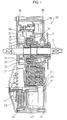
- an electric bicycle 1 designed to have the manual pedaling force assisted by the electric motor driving unit comprises a main pipe 2, a sheet pipe 3, a crank 5 connected to a crank shaft 4, a pedal 6 attached to said crank 5, a sprocket 7 attached to the crank shat 4, a rear wheel sprocket 9 attached to a rear wheel 8, a chain 10 mounted between the sprockets 7 and 9, a battery case 12 having a battery 11 stored therein, and an electric motor driving unit 20 integrally constructed in the region of the crank shaft located under the vehicle body center.
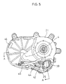
- the case of the electric motor driving unit 20 is comprised of a box 21, a gear cover 22, a motor cover 23, and a lid 24. These components are sealed by a gasket 25, the electric motor driving unit 20 being of waterproof construction. However, changes in the pressure in the case due to temperature changes are eliminated by the use of a breathing pipe 26.
- a speed reducer 27 Housed in the case defined by said box 21 and gear cover 22 are a speed reducer 27, a torque detector 30 and a speed detector 42. Further, in the area of the case defined by the recess of the gear cover 22 and the cover 23, there is housed a flat type electric motor 41. In addition, making the electric motor 41 flat makes it easier to secure the space for storing control circuit 40 in the box 21.
- the torque detector 30 housed in said electric motor driving unit 20 detects the manual pedaling force which is transmitted to the crank shaft 4 through the pedal 6 and crank 5.
- the torque detector 30, as shown in Figs. 1 and 4, is a detector using a planetary gear type differential mechanism which comprises an internal gear 31, a plant gear 32 and a sun gear 33, the manual torque transmitted to the crank shat 4 being transmitted to a carrier 34. And the internal gear 31 is connected to said sprocket 7.
- the amount of manual rotation approximately proportional to the manual torque is converted into a voltage value by using a potentiometer 39, thereby detecting the torque.
- assistance in driving force is effected within the specified range by the circuit 40 housed in the electric motor driving unit 20.
- the current for the circuit 40 and electric motor 41 is supplied from the battery 11 stored in battery case 12.
- the driving force produced by the electric motor 41 is added to the manual pedaling force through the speed reducer 27 and transmitted to the sprocket 7.
- This rotating force transmitted to the sprocket 7 is then transmitted to the rear wheel 8 through the chain 10 and rear wheel sprocket 8.
- the speed detector 42 detects the rpm by means of the ridges and recesses of the gear, and the driving force of the electric motor 41 is controlled according to the schedule by the circuit 40.
- the circuit 40 is housed in the case defined by the lid 24 and the box 21 in the region where the electric motor 41 is housed, the circuit 40 being attached to the back of the lid 24.
- the lead 43 of the electric motor 41, the lead 44 of the potentiometer 39 of the torque detector 30 and the lead 45 of the speed detector 42 are connected to the circuit 40.
- the box 21 and the gear cover 22 are formed with a through-hole 46 which connects the case defined by the gear cover 22 and motor cover 23 to the case defined by the box 21 and lid 24, thereby effecting the wiring between the lead 43 of the electric motor 43 and the circuit 40.
- the electric motor driving unit 20 has its components, i.e., the electric motor 41, speed reducer 27, torque detector 30 for detecting the pedaling force, speed detector 42 for detecting the vehicle speed, and the circuit 40 for controlling said electric motor 41, integrally constructed.
- the box 21, gear cover 22, motor cover 23 and lid 24 are formed by aluminum die casting (an example of metal). Therefore, since the circuit 40 is stored in the case defined by the aluminum box 21 and aluminum lid 24, the shield effect prevents malfunction due to external noise. Further, this construction, which is immune to external noise, hardly sends out noise.
- the torque detector 30 and speed detector 42 are connected to the circuit 40 within said case by the potentiometer lead 44 and speed detector lead 45. Since the wiring is effected within the metal case in this manner, it is possible to prevent noise from getting on the leads and to prevent the torque detector 30 and speed detector 42 from malfunctioning.
- the electric motor driving unit 20 is integrally covered with the metal box 21 and covers 22, 23, it has a sufficient strength to withstand external impact load. Particularly, since the circuit 40 is protected by the metal lid 24, it is no longer necessary to attach a resin cover to effect wiring between the circuit 40 and the leads 43, 44, 45.
- the circuit 40 is fixed in position in that power elements 48 soldered to the circuit 40 are contacted with the power element attaching surface of the lid 24 and fixed thereto by bolts 49 and nuts 50.
- resin is filled in the circuit section's outer peripheral ridge 51.
- the numeral 52 denotes a key switch connector; 53 denotes an LED light connector; and 54 denotes battery terminals.
- the numeral 55 denotes a grommet for waterproofness, attached to the box 21.
Landscapes
- Engineering & Computer Science (AREA)
- Chemical & Material Sciences (AREA)
- Combustion & Propulsion (AREA)
- Transportation (AREA)
- Mechanical Engineering (AREA)
- Electric Propulsion And Braking For Vehicles (AREA)
Applications Claiming Priority (3)
| Application Number | Priority Date | Filing Date | Title |
|---|---|---|---|
| JP21397296 | 1996-08-14 | ||
| JP21397296A JP3432366B2 (ja) | 1996-08-14 | 1996-08-14 | 電気自転車 |
| JP213972/96 | 1996-08-14 |
Publications (3)
| Publication Number | Publication Date |
|---|---|
| EP0825101A2 true EP0825101A2 (fr) | 1998-02-25 |
| EP0825101A3 EP0825101A3 (fr) | 1998-12-09 |
| EP0825101B1 EP0825101B1 (fr) | 2004-06-23 |
Family
ID=16648120
Family Applications (1)
| Application Number | Title | Priority Date | Filing Date |
|---|---|---|---|
| EP97113854A Expired - Lifetime EP0825101B1 (fr) | 1996-08-14 | 1997-08-11 | Bicyclette à assistance électrique |
Country Status (3)
| Country | Link |
|---|---|
| EP (1) | EP0825101B1 (fr) |
| JP (1) | JP3432366B2 (fr) |
| DE (1) | DE69729611T2 (fr) |
Cited By (15)
| Publication number | Priority date | Publication date | Assignee | Title |
|---|---|---|---|---|
| EP1092618A3 (fr) * | 1999-10-13 | 2002-11-06 | Honda Giken Kogyo Kabushiki Kaisha | Unité à assistance motorisée |
| EP1092622A3 (fr) * | 1999-10-13 | 2003-05-14 | Honda Giken Kogyo Kabushiki Kaisha | Unité à assistance motorisée |
| EP1092623A3 (fr) * | 1999-10-13 | 2003-11-05 | Honda Giken Kogyo Kabushiki Kaisha | Bicyclette assistée à moteur |
| EP1564130A1 (fr) * | 2004-02-10 | 2005-08-17 | HONDA MOTOR CO., Ltd. | Boíte de vitesses pour bicyclettes |
| US7134706B2 (en) | 2004-01-20 | 2006-11-14 | Honda Motor Co., Ltd. | Unlocking member arranging structure for vehicles |
| US7198129B2 (en) | 2003-10-10 | 2007-04-03 | Honda Motor Co., Ltd. | Motorcycle |
| US7562734B2 (en) | 2003-10-10 | 2009-07-21 | Honda Motor Co., Ltd. | Luggage storage device for a motorcycle |
| WO2012025444A1 (fr) * | 2010-08-27 | 2012-03-01 | Robert Bosch Gmbh | Unité d'entraînement destinée à une bicyclette électrique et procédé de montage d'une unité d'entraînement sur une bicyclette électrique |
| US8312623B2 (en) | 2007-03-29 | 2012-11-20 | Fry's Metals, Inc. | Methods for producing electrical conductors |
| CN107010167A (zh) * | 2015-11-27 | 2017-08-04 | 株式会社岛野 | 自行车用驱动单元 |
| WO2018081996A1 (fr) * | 2016-11-04 | 2018-05-11 | 北京轻客智能科技有限责任公司 | Dispositif de détection de couple et véhicule à assistance électrique mettant en œuvre ledit dispositif de détection de couple |
| WO2018219597A1 (fr) * | 2017-05-30 | 2018-12-06 | Disco Drives Kirschey Gmbh | Unité d'entraînement pour une bicyclette |
| EP3012181B1 (fr) * | 2014-10-21 | 2019-01-02 | Wuxi Truckrun Motor Co., Ltd. | Système d'entraînement de moteur intermédiaire pour une bicyclette électrique |
| EP3790171A4 (fr) * | 2018-03-13 | 2021-07-21 | Panasonic Intellectual Property Management Co., Ltd. | Unité de moteur de bicyclette électrique et bicyclette électrique |
| FR3116793A1 (fr) * | 2020-11-27 | 2022-06-03 | Valeo Embrayages | Boîtier pour dispositif de changement de vitesse pour engin de mobilité |
Families Citing this family (17)
| Publication number | Priority date | Publication date | Assignee | Title |
|---|---|---|---|---|
| DE102010009649B4 (de) | 2010-03-02 | 2017-01-05 | Karlheinz Nicolai | Fahrrad mit elektrischem Hilfsantrieb |
| DE102010017829A1 (de) | 2010-04-20 | 2011-10-20 | Inwall Ag | Motor-Getriebe-Einheit |
| DE102010026404A1 (de) | 2010-07-07 | 2012-01-12 | Schaeffler Technologies Gmbh & Co. Kg | Elektrischer Hilfsantriebsmotor für ein Fahrrad |
| DE102011005520A1 (de) | 2011-03-14 | 2012-09-20 | Grace Gmbh & Co.Kg | Zweiradrahmen, insbesondere für Elektrofahrräder, mit eine Aufnahme aufspannendes Profilelement |
| JP6218167B2 (ja) * | 2013-03-29 | 2017-10-25 | ヤマハ発動機株式会社 | 駆動ユニット及び電動補助自転車 |
| EP2998211B1 (fr) * | 2013-05-16 | 2017-12-20 | Panasonic Intellectual Property Management Co., Ltd. | Vélo électriquement assisté |
| DE202014101083U1 (de) | 2014-03-11 | 2015-06-12 | Rose Bikes Gmbh | Fahrrad mit einem Elektromotor |
| DE102014015318A1 (de) | 2014-10-17 | 2016-04-21 | Drive & Innovation Gmbh & Co. Kg | Getriebeanordnung für einen an einen Rahmen eines mittels Tretkurbel angetriebenen Fahrzeugs anbaubaren Hilfsantrieb |
| DE102015010817A1 (de) | 2015-08-23 | 2017-02-23 | Karlheinz Nicolai | Halterung mit klappbarer Schutzabdeckung für Energiespeicher mit schneller werkzeugloser Wechselmöglichkeit von einem oder mehreren Energiespeichern für den Einsatz an Geräten und Fahrzeugen |
| CN105691535A (zh) * | 2016-01-04 | 2016-06-22 | 哈尔滨理工大学 | 双驱式电动自行车 |
| JP6429822B2 (ja) * | 2016-03-31 | 2018-11-28 | 太陽誘電株式会社 | 電動アシスト車および電動アシスト車用モジュール |
| JP6927799B2 (ja) * | 2017-08-25 | 2021-09-01 | 株式会社シマノ | 自転車用ドライブユニット |
| JP6447897B2 (ja) * | 2018-01-18 | 2019-01-09 | パナソニックIpマネジメント株式会社 | モータ駆動ユニット及び電動アシスト自転車 |
| JP6391034B2 (ja) * | 2018-01-18 | 2018-09-19 | パナソニックIpマネジメント株式会社 | モータ駆動ユニット及び電動アシスト自転車 |
| JP6384819B2 (ja) * | 2018-01-18 | 2018-09-05 | パナソニックIpマネジメント株式会社 | モータ駆動ユニット及び電動アシスト自転車 |
| JP6436328B1 (ja) * | 2018-09-27 | 2018-12-12 | パナソニックIpマネジメント株式会社 | モータ駆動ユニット及び電動アシスト自転車 |
| JP6548103B2 (ja) * | 2019-04-10 | 2019-07-24 | パナソニックIpマネジメント株式会社 | モータ駆動ユニット及び電動アシスト自転車 |
Citations (3)
| Publication number | Priority date | Publication date | Assignee | Title |
|---|---|---|---|---|
| JPH04244496A (ja) | 1991-01-31 | 1992-09-01 | Honda Motor Co Ltd | 駆動力補助装置付き自転車 |
| JPH05262273A (ja) | 1992-03-19 | 1993-10-12 | Sanyo Electric Co Ltd | 電気自転車 |
| JPH06107266A (ja) | 1992-09-30 | 1994-04-19 | Yamaha Motor Co Ltd | 電動モータ付き自転車 |
Family Cites Families (3)
| Publication number | Priority date | Publication date | Assignee | Title |
|---|---|---|---|---|
| DE3117415A1 (de) * | 1981-05-02 | 1982-11-18 | Wolfgang Dr.-Ing. 8740 Bad Neustadt Volkrodt | Zwei- oder mehrraedriges fahzeug mit kettenlosem antrieb |
| TW467091U (en) * | 1994-03-29 | 2001-12-01 | Sanyo Electric Co | Electric bicycle |
| JPH09277978A (ja) * | 1996-04-12 | 1997-10-28 | Matsushita Electric Ind Co Ltd | 電気自転車 |
-
1996
- 1996-08-14 JP JP21397296A patent/JP3432366B2/ja not_active Expired - Lifetime
-
1997
- 1997-08-11 DE DE69729611T patent/DE69729611T2/de not_active Expired - Fee Related
- 1997-08-11 EP EP97113854A patent/EP0825101B1/fr not_active Expired - Lifetime
Patent Citations (3)
| Publication number | Priority date | Publication date | Assignee | Title |
|---|---|---|---|---|
| JPH04244496A (ja) | 1991-01-31 | 1992-09-01 | Honda Motor Co Ltd | 駆動力補助装置付き自転車 |
| JPH05262273A (ja) | 1992-03-19 | 1993-10-12 | Sanyo Electric Co Ltd | 電気自転車 |
| JPH06107266A (ja) | 1992-09-30 | 1994-04-19 | Yamaha Motor Co Ltd | 電動モータ付き自転車 |
Cited By (15)
| Publication number | Priority date | Publication date | Assignee | Title |
|---|---|---|---|---|
| EP1092622A3 (fr) * | 1999-10-13 | 2003-05-14 | Honda Giken Kogyo Kabushiki Kaisha | Unité à assistance motorisée |
| EP1092623A3 (fr) * | 1999-10-13 | 2003-11-05 | Honda Giken Kogyo Kabushiki Kaisha | Bicyclette assistée à moteur |
| EP1092618A3 (fr) * | 1999-10-13 | 2002-11-06 | Honda Giken Kogyo Kabushiki Kaisha | Unité à assistance motorisée |
| US7562734B2 (en) | 2003-10-10 | 2009-07-21 | Honda Motor Co., Ltd. | Luggage storage device for a motorcycle |
| US7198129B2 (en) | 2003-10-10 | 2007-04-03 | Honda Motor Co., Ltd. | Motorcycle |
| US7134706B2 (en) | 2004-01-20 | 2006-11-14 | Honda Motor Co., Ltd. | Unlocking member arranging structure for vehicles |
| EP1564130A1 (fr) * | 2004-02-10 | 2005-08-17 | HONDA MOTOR CO., Ltd. | Boíte de vitesses pour bicyclettes |
| US8312623B2 (en) | 2007-03-29 | 2012-11-20 | Fry's Metals, Inc. | Methods for producing electrical conductors |
| WO2012025444A1 (fr) * | 2010-08-27 | 2012-03-01 | Robert Bosch Gmbh | Unité d'entraînement destinée à une bicyclette électrique et procédé de montage d'une unité d'entraînement sur une bicyclette électrique |
| EP3012181B1 (fr) * | 2014-10-21 | 2019-01-02 | Wuxi Truckrun Motor Co., Ltd. | Système d'entraînement de moteur intermédiaire pour une bicyclette électrique |
| CN107010167A (zh) * | 2015-11-27 | 2017-08-04 | 株式会社岛野 | 自行车用驱动单元 |
| WO2018081996A1 (fr) * | 2016-11-04 | 2018-05-11 | 北京轻客智能科技有限责任公司 | Dispositif de détection de couple et véhicule à assistance électrique mettant en œuvre ledit dispositif de détection de couple |
| WO2018219597A1 (fr) * | 2017-05-30 | 2018-12-06 | Disco Drives Kirschey Gmbh | Unité d'entraînement pour une bicyclette |
| EP3790171A4 (fr) * | 2018-03-13 | 2021-07-21 | Panasonic Intellectual Property Management Co., Ltd. | Unité de moteur de bicyclette électrique et bicyclette électrique |
| FR3116793A1 (fr) * | 2020-11-27 | 2022-06-03 | Valeo Embrayages | Boîtier pour dispositif de changement de vitesse pour engin de mobilité |
Also Published As
| Publication number | Publication date |
|---|---|
| DE69729611T2 (de) | 2009-09-24 |
| JPH1059259A (ja) | 1998-03-03 |
| EP0825101B1 (fr) | 2004-06-23 |
| JP3432366B2 (ja) | 2003-08-04 |
| EP0825101A3 (fr) | 1998-12-09 |
| DE69729611D1 (de) | 2004-07-29 |
Similar Documents
| Publication | Publication Date | Title |
|---|---|---|
| EP0825101A2 (fr) | Bicyclette à assistance électrique | |
| US6073717A (en) | Electric motor assisted vehicle | |
| EP0776818B1 (fr) | Bicyclette à assistance électrique | |
| EP0531200B1 (fr) | Groupe de propulsion de véhicule à moteur | |
| US11577774B2 (en) | Electric drive device and electric power steering device | |
| US10826355B2 (en) | Electric drive device and electric power steering device | |
| CA2918107C (fr) | Systeme de commande monte au centre d'une bicyclette | |
| US11407443B2 (en) | Electric drive device and electric power steering device | |
| US11381131B2 (en) | Electric drive device and electric power steering device | |
| JP3617728B2 (ja) | 電動補助車両 | |
| EP2279938A1 (fr) | Dispositif de commande de moteur et véhicule électrique équipé de celui-ci | |
| EP0822133A1 (fr) | Bicyclette à assistance électrique | |
| US10797566B2 (en) | Electric drive device and electric power steering device | |
| CN112018929B (zh) | 轮内马达单元和电动车辆 | |
| JPH06239286A (ja) | 電動自転車 | |
| CN212373595U (zh) | 一种同腔液冷式中置电机 | |
| JP3832705B2 (ja) | 電動補助ユニット | |
| TWI730555B (zh) | 電動二輪機車之動力單元構造 | |
| JP3996255B2 (ja) | 電動二輪車 | |
| JP3387153B2 (ja) | 電動車両 | |
| JPH115584A (ja) | 電動自転車用駆動ユニット構造 | |
| WO2019240146A1 (fr) | Dispositif d'entraînement électrique et dispositif de direction assistée électrique | |
| CN216070377U (zh) | 一种电动自行车中置电机 | |
| EP1092618B1 (fr) | Unité à assistance motorisée | |
| CN214225202U (zh) | 一种汽车电子油门速度传感器 |
Legal Events
| Date | Code | Title | Description |
|---|---|---|---|
| PUAI | Public reference made under article 153(3) epc to a published international application that has entered the european phase |
Free format text: ORIGINAL CODE: 0009012 |
|
| AK | Designated contracting states |
Kind code of ref document: A2 Designated state(s): DE FR NL |
|
| AX | Request for extension of the european patent |
Free format text: AL;LT;LV;RO;SI |
|
| PUAL | Search report despatched |
Free format text: ORIGINAL CODE: 0009013 |
|
| AK | Designated contracting states |
Kind code of ref document: A3 Designated state(s): AT BE CH DE DK ES FI FR GB GR IE IT LI LU MC NL PT SE |
|
| AX | Request for extension of the european patent |
Free format text: AL;LT;LV;RO;SI |
|
| 17P | Request for examination filed |
Effective date: 19990212 |
|
| AKX | Designation fees paid |
Free format text: CH DE FR LI |
|
| RBV | Designated contracting states (corrected) |
Designated state(s): DE FR NL |
|
| 17Q | First examination report despatched |
Effective date: 20020826 |
|
| GRAP | Despatch of communication of intention to grant a patent |
Free format text: ORIGINAL CODE: EPIDOSNIGR1 |
|
| GRAS | Grant fee paid |
Free format text: ORIGINAL CODE: EPIDOSNIGR3 |
|
| GRAA | (expected) grant |
Free format text: ORIGINAL CODE: 0009210 |
|
| AK | Designated contracting states |
Kind code of ref document: B1 Designated state(s): DE FR NL |
|
| REF | Corresponds to: |
Ref document number: 69729611 Country of ref document: DE Date of ref document: 20040729 Kind code of ref document: P |
|
| ET | Fr: translation filed | ||
| PLBE | No opposition filed within time limit |
Free format text: ORIGINAL CODE: 0009261 |
|
| STAA | Information on the status of an ep patent application or granted ep patent |
Free format text: STATUS: NO OPPOSITION FILED WITHIN TIME LIMIT |
|
| 26N | No opposition filed |
Effective date: 20050324 |
|
| PGFP | Annual fee paid to national office [announced via postgrant information from national office to epo] |
Ref country code: NL Payment date: 20080815 Year of fee payment: 12 Ref country code: DE Payment date: 20080821 Year of fee payment: 12 |
|
| PGFP | Annual fee paid to national office [announced via postgrant information from national office to epo] |
Ref country code: FR Payment date: 20080818 Year of fee payment: 12 |
|
| REG | Reference to a national code |
Ref country code: NL Ref legal event code: V1 Effective date: 20100301 |
|
| REG | Reference to a national code |
Ref country code: FR Ref legal event code: ST Effective date: 20100430 |
|
| PG25 | Lapsed in a contracting state [announced via postgrant information from national office to epo] |
Ref country code: NL Free format text: LAPSE BECAUSE OF NON-PAYMENT OF DUE FEES Effective date: 20100301 Ref country code: FR Free format text: LAPSE BECAUSE OF NON-PAYMENT OF DUE FEES Effective date: 20090831 Ref country code: DE Free format text: LAPSE BECAUSE OF NON-PAYMENT OF DUE FEES Effective date: 20100302 |