EP0825065B1 - Befestigung für eine Abdeckung - Google Patents
Befestigung für eine Abdeckung Download PDFInfo
- Publication number
- EP0825065B1 EP0825065B1 EP97110995A EP97110995A EP0825065B1 EP 0825065 B1 EP0825065 B1 EP 0825065B1 EP 97110995 A EP97110995 A EP 97110995A EP 97110995 A EP97110995 A EP 97110995A EP 0825065 B1 EP0825065 B1 EP 0825065B1
- Authority
- EP
- European Patent Office
- Prior art keywords
- cover
- bearing point
- housing
- wedge
- selector lever
- Prior art date
- Legal status (The legal status is an assumption and is not a legal conclusion. Google has not performed a legal analysis and makes no representation as to the accuracy of the status listed.)
- Expired - Lifetime
Links
Images
Classifications
-
- B—PERFORMING OPERATIONS; TRANSPORTING
- B60—VEHICLES IN GENERAL
- B60K—ARRANGEMENT OR MOUNTING OF PROPULSION UNITS OR OF TRANSMISSIONS IN VEHICLES; ARRANGEMENT OR MOUNTING OF PLURAL DIVERSE PRIME-MOVERS IN VEHICLES; AUXILIARY DRIVES FOR VEHICLES; INSTRUMENTATION OR DASHBOARDS FOR VEHICLES; ARRANGEMENTS IN CONNECTION WITH COOLING, AIR INTAKE, GAS EXHAUST OR FUEL SUPPLY OF PROPULSION UNITS IN VEHICLES
- B60K20/00—Arrangement or mounting of change-speed gearing control devices in vehicles
- B60K20/02—Arrangement or mounting of change-speed gearing control devices in vehicles of initiating means
- B60K20/04—Arrangement or mounting of change-speed gearing control devices in vehicles of initiating means floor mounted
-
- Y—GENERAL TAGGING OF NEW TECHNOLOGICAL DEVELOPMENTS; GENERAL TAGGING OF CROSS-SECTIONAL TECHNOLOGIES SPANNING OVER SEVERAL SECTIONS OF THE IPC; TECHNICAL SUBJECTS COVERED BY FORMER USPC CROSS-REFERENCE ART COLLECTIONS [XRACs] AND DIGESTS
- Y10—TECHNICAL SUBJECTS COVERED BY FORMER USPC
- Y10T—TECHNICAL SUBJECTS COVERED BY FORMER US CLASSIFICATION
- Y10T74/00—Machine element or mechanism
- Y10T74/20—Control lever and linkage systems
- Y10T74/20012—Multiple controlled elements
- Y10T74/20018—Transmission control
- Y10T74/20177—Particular element [e.g., shift fork, template, etc.]
-
- Y—GENERAL TAGGING OF NEW TECHNOLOGICAL DEVELOPMENTS; GENERAL TAGGING OF CROSS-SECTIONAL TECHNOLOGIES SPANNING OVER SEVERAL SECTIONS OF THE IPC; TECHNICAL SUBJECTS COVERED BY FORMER USPC CROSS-REFERENCE ART COLLECTIONS [XRACs] AND DIGESTS
- Y10—TECHNICAL SUBJECTS COVERED BY FORMER USPC
- Y10T—TECHNICAL SUBJECTS COVERED BY FORMER US CLASSIFICATION
- Y10T74/00—Machine element or mechanism
- Y10T74/21—Elements
- Y10T74/2186—Gear casings
Definitions
- the invention relates to a cover for a selector lever housing, according to the preamble of expression 1.
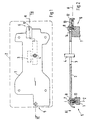
- the selector lever housing 1 shown in Fig. 1 in a first embodiment is with a Cover 2 shown in dashed lines, in which an H-shaped opening 3 for the passage of a Selector lever 4 is provided.
- the cover 2 is by means of a first bearing point 5 and a second bearing point 6 existing attachment to the selector lever housing 1 held and by as a fastener, here Screws 7, 8, attached.
- the first bearing point 5 is cylindrical.
- the cylinder axis Z runs parallel to one Positioning direction A of the cover 2 on the selector lever housing 1.
- the screw 7 engages in a bore 10 which is concentric within the first Bearing point 5 is arranged.
- the second bearing point 6 consists of a wedge-shaped receptacle 12 that is open toward the mounting direction A. and a corresponding, also wedge-shaped projection 13 of the Cover 2.
- a wedge axis K of the receptacle 12 lies in a plane perpendicular to the mounting direction A. and runs close to the first bearing point 5 parallel to the main length of the opening 3, which is given here by the long legs of the H-shaped opening 3.
- the wedge-shaped receptacle 12 is open at the bottom; however, this is not absolutely necessary, but rather it is only important to ensure that the projection 13 in the side surfaces of the receptacle 12 for System arrives and does not sit on an existing base area of the receptacle 12.
- the second screw 8 is next to the receptacle 12 and thus also arranged next to the projection 13.
- the projection 13 is inside the receptacle 12 movable along the wedge axis K, so that within the cover 2 for the screw 8 Elongated hole 14 is provided, which is dimensioned so that it the length tolerances of the cover 2 in can compensate for the position of the screw 8.
- the first cylindrical bearing point ensures that the cover 2 at this point with respect to the Selector lever housing 1 is positioned exactly.
- the angular position of the cover 2 relative to that Selector lever housing 1 is set solely by the second cylindrical bearing point 6, since the Screw 7 is arranged concentrically to the first bearing point 5 and so with respect to the angular position the cover has no effect. Since the cover 2 and the selector lever housing 1 before Tightening the mounting screws 7, 8 are not yet connected to each other Place the cover 2 on the selector lever housing 1 of the projection 13 of the cover 2 in the wedge-shaped receptacle 12 are displaced and so tolerances in the longitudinal direction of the cover 2nd compensate. It is particularly advantageous here that the wedge axis K parallel to the main length extension the recess 3 runs because there are now length tolerances in the cover 2 or in Selector lever housing 1 cannot affect the guidance of selector lever 4 in opening 3.
Landscapes
- Engineering & Computer Science (AREA)
- Chemical & Material Sciences (AREA)
- Combustion & Propulsion (AREA)
- Transportation (AREA)
- Mechanical Engineering (AREA)
- Arrangement Or Mounting Of Control Devices For Change-Speed Gearing (AREA)
- Mechanical Control Devices (AREA)
- Casings For Electric Apparatus (AREA)
- Vehicle Step Arrangements And Article Storage (AREA)
Description
- Fig. 1
- zu einem ersten Ausführungsbeispiel eine Draufsicht auf ein Wählhebelgehäuse mit zwei Lagerpunkten,
- Fig. 2
- einen Schnitt durch eine Abdeckung des Wählhebelgehäuses nach der Linie II-II der Fig. 1 und
Claims (2)
- Abdeckung (2) für ein Wählhebelgehäuse (1), welche an zwei Lagerpunkten (5, 6) an dem Wählhebelgehäuse (1) gehalten und durch Befestigungsmittel (7,8) an dem Wählhebelgehäuse (1) befestigt ist, wobei der erste Lagerpunkt (5) zylindrisch ausgebildet ist und die Zylinderachse (Z) des ersten Lagerpunktes (5) parallel zu einer Aufsetzrichtung (A) der Abdeckung (2) liegt und wobei der zweite Lagerpunkt (6) keilförmig ausgebildet ist, dadurch gekennzeichnet, daß die Keilachse (K) des zweiten keilförmig ausgebildeten Lagerpunktes (6) senkrecht zur Aufsetzrichtung der Abdeckung (2) und parallel zur Hauptlängenerstreckung einer in der Abdeckung (2) vorgesehenen Durchtrittsöffnung (3) für einen Wählhebel (4) angeordnet ist.
- Abdeckung nach Anspruch 1, dadurch gekennzeichnet, daß die Befestigungsmittel (7, 8) der Abdeckung am Gehäuse im Bereich der Lagerpunkte (5, 6) vorgesehen sind.
Applications Claiming Priority (2)
| Application Number | Priority Date | Filing Date | Title |
|---|---|---|---|
| DE19631941 | 1996-08-08 | ||
| DE19631941A DE19631941C2 (de) | 1996-08-08 | 1996-08-08 | Befestigung für eine Abdeckung |
Publications (3)
| Publication Number | Publication Date |
|---|---|
| EP0825065A2 EP0825065A2 (de) | 1998-02-25 |
| EP0825065A3 EP0825065A3 (de) | 2000-01-05 |
| EP0825065B1 true EP0825065B1 (de) | 2003-01-02 |
Family
ID=7802068
Family Applications (1)
| Application Number | Title | Priority Date | Filing Date |
|---|---|---|---|
| EP97110995A Expired - Lifetime EP0825065B1 (de) | 1996-08-08 | 1997-07-02 | Befestigung für eine Abdeckung |
Country Status (5)
| Country | Link |
|---|---|
| US (1) | US6003399A (de) |
| EP (1) | EP0825065B1 (de) |
| JP (1) | JPH1082499A (de) |
| KR (1) | KR19980018465A (de) |
| DE (2) | DE19631941C2 (de) |
Families Citing this family (2)
| Publication number | Priority date | Publication date | Assignee | Title |
|---|---|---|---|---|
| JP3557123B2 (ja) * | 1999-05-18 | 2004-08-25 | 富士機工株式会社 | 樹脂成形品のボルト締結構造 |
| KR101462919B1 (ko) * | 2013-11-15 | 2014-11-19 | 현대자동차주식회사 | 공용변속레버와 브라켓 체결구조 |
Family Cites Families (12)
| Publication number | Priority date | Publication date | Assignee | Title |
|---|---|---|---|---|
| DE3420586A1 (de) * | 1984-06-01 | 1985-12-05 | Siemens AG, 1000 Berlin und 8000 München | Kompaktfernsprecher |
| JPH0236647A (ja) * | 1988-07-27 | 1990-02-06 | Tamura Electric Works Ltd | 送受話器におけるダイヤルユニツトの組込構造 |
| DE9102932U1 (de) * | 1991-03-12 | 1991-08-01 | Apra-Gerätebau Ing.grad. Wolfgang Appenzeller und Wilfried Rademacher, 5568 Daun | System aus stapelbaren Modulgehäusen |
| US5598746A (en) * | 1993-03-12 | 1997-02-04 | Chen; Ching-Ti | Transmission assembly |
| JPH0818630B2 (ja) * | 1993-11-12 | 1996-02-28 | 株式会社ソフトサービス | コンパクトディスク万引き防犯タグカバー |
| IT233424Y1 (it) * | 1994-05-13 | 2000-01-28 | Ferrari Franco | Elemento di fissaggio per elementi di ferramenta |
| JPH07336263A (ja) * | 1994-06-03 | 1995-12-22 | Kokusai Electric Co Ltd | キーボタン部の防沫構造 |
| DE9419679U1 (de) * | 1994-12-08 | 1995-03-02 | Hama GmbH & Co, 86653 Monheim | Halterungsvorrichtung für ein Funktelefon in einem Fahrzeug |
| US5494158A (en) * | 1994-12-29 | 1996-02-27 | Mmct Holdings, Llc | Syringe sales and disposal box |
| US5584207A (en) * | 1995-03-20 | 1996-12-17 | Hewlett-Packard Company | Integrated drive system |
| US5778411A (en) * | 1995-05-16 | 1998-07-07 | Symbios, Inc. | Method for virtual to physical mapping in a mapped compressed virtual storage subsystem |
| JP3250598B2 (ja) * | 1995-06-28 | 2002-01-28 | 株式会社小糸製作所 | セルフロッキングナット |
-
1996
- 1996-08-08 DE DE19631941A patent/DE19631941C2/de not_active Expired - Fee Related
-
1997
- 1997-07-02 DE DE59709045T patent/DE59709045D1/de not_active Expired - Fee Related
- 1997-07-02 EP EP97110995A patent/EP0825065B1/de not_active Expired - Lifetime
- 1997-08-07 KR KR1019970037737A patent/KR19980018465A/ko not_active Withdrawn
- 1997-08-08 JP JP9214683A patent/JPH1082499A/ja active Pending
- 1997-08-08 US US08/908,719 patent/US6003399A/en not_active Expired - Fee Related
Also Published As
| Publication number | Publication date |
|---|---|
| EP0825065A2 (de) | 1998-02-25 |
| US6003399A (en) | 1999-12-21 |
| DE19631941C2 (de) | 1999-02-25 |
| KR19980018465A (ko) | 1998-06-05 |
| DE19631941A1 (de) | 1998-02-12 |
| JPH1082499A (ja) | 1998-03-31 |
| EP0825065A3 (de) | 2000-01-05 |
| DE59709045D1 (de) | 2003-02-06 |
Similar Documents
| Publication | Publication Date | Title |
|---|---|---|
| EP1862767B1 (de) | Sicherheits-Positionssensor für Zylinder, Zylinder mit einem solchen Positionssensor | |
| DE4306769A1 (de) | Druckregelvorrichtung für eine schlupfgeregelte hydraulische Bremsanlage, insbesondere für Kraftfahrzeuge | |
| DE3530776C2 (de) | ||
| DE69208423T2 (de) | Einstellungseinrichtung für Scheinwerfer mit Schnappverbindung | |
| EP0411239B1 (de) | Steckerträger zum Anbau an ein Aggregatgehäuse | |
| DE7705465U1 (de) | Grundplatte fuer verdeckt angeordnete scharniere, insbesondere moebelscharniere | |
| DE69813438T2 (de) | Vorrichtung zur variablen Abdeckung von elektrischen kabelführungen | |
| EP3851249A1 (de) | Werkstückspannvorrichtung | |
| DE4032865C2 (de) | Schraubverbindung | |
| EP0478639B1 (de) | Scharnier | |
| EP0873816B1 (de) | Positionier-Schnellspannzylinder | |
| EP0295237B1 (de) | Weichenbetätigungsvorrichtung | |
| EP0223186A2 (de) | Justierbares Tür- oder Fensterband | |
| DE4142598C1 (en) | Glove pocket lid hinge - has fastener plate allocated to body-fixed tap with straps allowing plate to move in two dimensions relative to support | |
| EP0739680A1 (de) | Vorrichtung zum Einrichten eines Oberteils relativ zu einem Unterteil | |
| DE19631941C2 (de) | Befestigung für eine Abdeckung | |
| DE3423037A1 (de) | Scharnier, insbesondere fuer eine dreidimensional einstellbare fahrzeugtuere | |
| EP0269666B1 (de) | Verbindungseinrichtung | |
| EP0532454A1 (de) | Befestigungsvorrichtung für einen stationären Deckel einer Karde | |
| EP1065339B1 (de) | Befestigungsvorrichtung für Bandlappen von Scharnieren | |
| EP0423474A1 (de) | Vorrichtung zum lösbaren Verbinden von zwei Profilstäben | |
| EP0562500B1 (de) | Profilzylinderrosette | |
| EP1376067B1 (de) | Vorrichtung zur Befestigung eines Sensors in einer Nut | |
| DE69505935T2 (de) | Vorrichtung zur Befestigung einer Anordnung an einer Säule, insbesondere für die Befestigung einer elektrischen Schaltvorrichtung an einer Kraftfahrzeuglenksäule | |
| DE10000702A1 (de) | Winkelschleifer |
Legal Events
| Date | Code | Title | Description |
|---|---|---|---|
| PUAI | Public reference made under article 153(3) epc to a published international application that has entered the european phase |
Free format text: ORIGINAL CODE: 0009012 |
|
| AK | Designated contracting states |
Kind code of ref document: A2 Designated state(s): DE FR GB IT |
|
| AX | Request for extension of the european patent |
Free format text: AL;LT;LV;RO;SI |
|
| PUAL | Search report despatched |
Free format text: ORIGINAL CODE: 0009013 |
|
| AK | Designated contracting states |
Kind code of ref document: A3 Designated state(s): AT BE CH DE DK ES FI FR GB GR IE IT LI LU MC NL PT SE |
|
| AX | Request for extension of the european patent |
Free format text: AL;LT;LV;RO;SI |
|
| RIC1 | Information provided on ipc code assigned before grant |
Free format text: 7B 60R 11/02 A, 7H 04M 1/02 B |
|
| 17P | Request for examination filed |
Effective date: 20000126 |
|
| AKX | Designation fees paid |
Free format text: DE FR GB IT |
|
| 17Q | First examination report despatched |
Effective date: 20010223 |
|
| GRAH | Despatch of communication of intention to grant a patent |
Free format text: ORIGINAL CODE: EPIDOS IGRA |
|
| GRAH | Despatch of communication of intention to grant a patent |
Free format text: ORIGINAL CODE: EPIDOS IGRA |
|
| GRAA | (expected) grant |
Free format text: ORIGINAL CODE: 0009210 |
|
| AK | Designated contracting states |
Kind code of ref document: B1 Designated state(s): DE FR GB IT |
|
| REG | Reference to a national code |
Ref country code: GB Ref legal event code: FG4D Free format text: 20030102:NOT ENGLISH |
|
| REF | Corresponds to: |
Ref document number: 59709045 Country of ref document: DE Date of ref document: 20030206 Kind code of ref document: P |
|
| GBT | Gb: translation of ep patent filed (gb section 77(6)(a)/1977) |
Effective date: 20030408 |
|
| ET | Fr: translation filed | ||
| PLBE | No opposition filed within time limit |
Free format text: ORIGINAL CODE: 0009261 |
|
| STAA | Information on the status of an ep patent application or granted ep patent |
Free format text: STATUS: NO OPPOSITION FILED WITHIN TIME LIMIT |
|
| 26N | No opposition filed |
Effective date: 20031003 |
|
| PGFP | Annual fee paid to national office [announced via postgrant information from national office to epo] |
Ref country code: DE Payment date: 20060622 Year of fee payment: 10 |
|
| PGFP | Annual fee paid to national office [announced via postgrant information from national office to epo] |
Ref country code: FR Payment date: 20060714 Year of fee payment: 10 |
|
| PGFP | Annual fee paid to national office [announced via postgrant information from national office to epo] |
Ref country code: GB Payment date: 20060720 Year of fee payment: 10 |
|
| PGFP | Annual fee paid to national office [announced via postgrant information from national office to epo] |
Ref country code: IT Payment date: 20060731 Year of fee payment: 10 |
|
| GBPC | Gb: european patent ceased through non-payment of renewal fee |
Effective date: 20070702 |
|
| PG25 | Lapsed in a contracting state [announced via postgrant information from national office to epo] |
Ref country code: DE Free format text: LAPSE BECAUSE OF NON-PAYMENT OF DUE FEES Effective date: 20080201 |
|
| PG25 | Lapsed in a contracting state [announced via postgrant information from national office to epo] |
Ref country code: GB Free format text: LAPSE BECAUSE OF NON-PAYMENT OF DUE FEES Effective date: 20070702 |
|
| REG | Reference to a national code |
Ref country code: FR Ref legal event code: ST Effective date: 20080331 |
|
| PG25 | Lapsed in a contracting state [announced via postgrant information from national office to epo] |
Ref country code: FR Free format text: LAPSE BECAUSE OF NON-PAYMENT OF DUE FEES Effective date: 20070731 |
|
| PG25 | Lapsed in a contracting state [announced via postgrant information from national office to epo] |
Ref country code: IT Free format text: LAPSE BECAUSE OF NON-PAYMENT OF DUE FEES Effective date: 20070702 |