EP0823680A2 - Verfahren und Vorrichtung zur Regelung von piezoelektrischen Vibrationen - Google Patents
Verfahren und Vorrichtung zur Regelung von piezoelektrischen Vibrationen Download PDFInfo
- Publication number
- EP0823680A2 EP0823680A2 EP97305310A EP97305310A EP0823680A2 EP 0823680 A2 EP0823680 A2 EP 0823680A2 EP 97305310 A EP97305310 A EP 97305310A EP 97305310 A EP97305310 A EP 97305310A EP 0823680 A2 EP0823680 A2 EP 0823680A2
- Authority
- EP
- European Patent Office
- Prior art keywords
- vibration
- current
- driving
- piezoelectric
- vibrating
- Prior art date
- Legal status (The legal status is an assumption and is not a legal conclusion. Google has not performed a legal analysis and makes no representation as to the accuracy of the status listed.)
- Granted
Links
Images


Classifications
-
- G—PHYSICS
- G05—CONTROLLING; REGULATING
- G05D—SYSTEMS FOR CONTROLLING OR REGULATING NON-ELECTRIC VARIABLES
- G05D19/00—Control of mechanical oscillations, e.g. of amplitude, of frequency, of phase
- G05D19/02—Control of mechanical oscillations, e.g. of amplitude, of frequency, of phase characterised by the use of electric means
Definitions
- the present invention relates to a method of and an apparatus for controlling piezoelectric vibration, and more particularly to a method of controlling vibration of a piezoelectric vibrator used for a parts feeder or the like to feed various types of parts by vibration as well as to a system for the same.
- the conventional type of vibration control for a parts feeder having a bowl for accommodating therein parts and discharging out each of the parts by exerting vibration to the bowl is effected by detecting the vibration of the bowl by a photoelectric transducer, feeding back an amplitude of the bowl obtained thereby to an amplitude controlling circuit, controlling a current fed to an electromagnet for driving the bowl, and driving the bowl at a constant amplitude at any time.
- parts accommodated in a bowl are fed from a parts discharging section to a shoot due to vibration of the bowl, and when each part slides down the shoot to be fed to an assembling machine, the part passing through the shoot is detected by a photoelectric sensing element to control the parts feeding rate.
- the parts feeder In a case of the method based on the conventional technology, the amount of parts supplied from the parts feeder varies according to changes in externai environments such as a voltage or temperature, and for this reason it is quite hard to feed parts with stability.
- the parts feeder is provided with such a sensor as a photoelectric transducer for detecting mechanical vibration or movement and converting it to an electric signal for feedback control. Accordingly, a control system becomes complicated with size of the apparatus increased, and also the cost becomes high.
- a method of controlling piezoelectric vibration in an apparatus having a piezoelectric vibrating element, a vibrating unit such as a parts feeder to which the piezoelectric vibrating element is attached, and a driving unit for driving the piezoelectric vibrating element comprises the steps of vibrating the piezoelectric vibrating element at a frequency at which the vibrating unit does not vibrate substantially; detecting a voltage, a current, and a phase difference between the voltage and the current while the piezoelectric vibrating element is driven at that frequency; driving the piezoelectric vibrating element at a frequency required for actually vibrating the vibrating unit; detecting a driving voltage and a driving current while the vibrating unit is vibrated; obtaining a current component not relating to the vibration of the vibrating unit from the detected voltages, currents, and the phase difference; computing a current component relating to the vibration of the vibrating unit from the current component not relating to the vibration; and controlling the current component relating to the
- the present invention provides a system for controlling piezoelectric vibration in an apparatus having a piezoelectric vibrating element, an vibrating unit such as a parts feeder to which the piezoelectric vibrating element is attached, and a driving unit for driving the piezoelectric vibrating element.
- the control system comprises a detector for detecting a voltage as well as a current for driving the piezoelectric vibrating element, a non-vibration current component computing means for obtaining a current not relating to the actual vibration of the vibrating unit non-vibration current component) based on the detected values while the vibrating unit is driven, a vibration current component computing means for computing a current component relating to the vibration of the vibrating unit from the obtained non-vibration current component, and a vibration current controlling means for controlling the vibration current component so as to be a constant value or a desired value.
- the vibration is directly controlled based on a driving current without using any sensor for detecting mechanical vibration, so that configuration thereof can be simplified and accurate control can be performed.
- Fig. 1 illustrates the general construction of a piezoelectric vibratory parts feeder incorporating therein a controller 10 according to the present invention.
- the parts feeder is substantially the same in construction as the conventional parts feeder.
- the parts feeder 1 comprises a bowl 2 provided with a side wall having a spiral parts feed track 3 formed on the inner peripheral surface thereof in the form of the gently upwardly sloping surface and a plurality of plate springs 4 attached at their upper ends to the underside of the bowl 2 with a predetermined angle formed therebetween.
- the lower ends of the respective plate springs 4 are directly connected to the upper ends of the corresponding piezoelectric vibrating elements 5.
- the lower ends of the piezoelectric vibrating elements 5 are secured to a base portion 6 at the same angle as the upper ends thereof.
- the piezoelectric vibrating elements 5 oscillate or vibrate when an electric power form a power supply is intermittently supplied to the piezoelectric vibrating elements 5.
- the oscillation or vibration of the piezoelectric vibrating elements 5 is transmitted via the plate springs 4 to the bowl 2 of the parts feeder 1.
- the base portion 6 is fixedly mounted on the floor surface via cushioning or damping members 7.
- the piezoelectric vibrating elements 5 jointly form a piezoelectric driving unit which constitutes a main portion of a vibration generating unit.
- the operation of the parts feeder is described, for example, in U.S. Pat. No. 5,472,079 issued Dec. 5, 1995 to Yagi et al., the teachings of which are hereby incorporated by reference.
- a sensor for detecting the amplitude is attached to the main body of the parts feeder 1 so as to control the vibration of the parts feeder at a constant amplitude according to feedback contrcl.
- the present invention aims to accurately control vibration of a vibrating unit using a piezoelectric vibrating element without using the sensor as described above.
- FIG. 3 An equivalent circuit of the piezoeiectric vibrating unit, for instance, the piezoelectric vibratory parts feeder is generally represented as shown in Fig. 3.
- the reference character i 1 indicates a current in proportion to mechanical vibration
- the reference character i 0 indicates a current not relating to the vibration. If the current relating to the vibration (hereinafter referred to as the vibration current") i 1 is separated from the current i t actually measured and the vibration current i 1 is controlled so that it is held at a constant value, the vibrating unit can be vibrated at a constant amplitude because there is a linear and proportional correlation between an amplitude of a piezoelectric vibrating element and the vibration current.
- the vibration current the current relating to the vibration
- This vibration current i 1 can be obtained by calculation from the equation (1) described below, wherein the current i 0 is measured when the piezoelectric vibrating element is driven at a frequency at which the vibrating unit little vibrates, and the current (total current) i t is measured when the vibrating unit is then actually vibrated.
- i 1 i t - i 0
- the piezoelectric vibration control system of this embodiment is, as shown in Fig. 4, directed to the parts feeder 1 as a vibrating unit for feeding various types of parts to a machine and includes the parts feeder 1 shown in Fig. 1, a power amplifier 12 which is a driving unit for driving the parts feeder 1, and a control unit 14 for outputting a drive signal to the power amplifier 12.
- the parts feeder 1 is provided with the piezoelectric vibrating elements 5 as shown in Fig. 1 and these piezoelectric vibrating elements 5 are vibrated by a driving power fed from the power amplifier 12. Further, the piezoelectric vibrating elements 5 of the parts feeder 1 are connected to a voltage detector 16 as well as to a current detector 18, and each output from the voltage detector 16 and current detector 18 is inputted to the control unit 14.
- An output terminal of a vibration current setter 20 for setting an amplitude of the piezoelectric vibrating elements 5 of the parts feeder 1 is connected to the control unit 14. Further, as shown in a second embodiment described hereinafter, in a case where frequency control is to be provided, an output terminal of a setter 22 for setting a frequency or an amplitude phase is also connected to the control unit 14.
- the controlling method of piezoelectric vibration control system is executed in the sequence as shown in Fig. 5. Since a frequency characteristic of an amplitude of the parts feeder is as shown in Fig. 6, at first, the piezoelectric vibrating elements 5 of the parts feeder 1 are driven at a frequency, fa, which is lower than the actual driving frequency and at which the parts feeder 1 hardly vibrates, and the voltage, Va, the current, Ia, and a phase difference, ⁇ , therebetween are detected while the piezoelectric vibrating elements are driven at that frequency.
- the current Ia is substantially equivalent to the current not relating to the vibration (non-vibration current) as shown in Fig. 7 because vibration of the parts feeder is not generated.
- the piezoelectric vibrating elements are driven at a frequency, fb, required for actually vibrating the parts feeder 1, and the driving voltage, Vb, and the driving current, Ib (total current) at the time of the actual vibration of the parts feeder are detected.
- the current component, Ib 0 not relating to the actual vibration is obtained according to the equation (2) described below from the detected driving voltage Vb and the voltage Va, current Ia, and phase difference ⁇ each detected at the frequency, fa, at which the parts feeder hardly oscillates, and the vibration current component Ib 1 at the time of the actual vibration is computed according to the equation (3) described below from the non-vibration current component Ib 0 and the driving current Ib.
- Ib 0 Vb ⁇ fb Va ⁇ fa ⁇ Ia wherein the currents Ib 0 and Ia indicate vectors.
- Fig. 7 showing frequency characteristics (sinusoidal wave drive) of currents and acceleration
- the total current and the acceleration are measured values
- the non-vibration current is a value obtained from the equation (2)
- the vibration current is a value obtained from the equation (3) mentioned above.
- the vibration current component Ib 1 obtained as described above is adjusted so that a parts feeder is driven at the most efficient and stable amplitude for discharging parts out. If the amplitude is too small, in the case of the parts feeder 1, efficiency is so low that parts do not move much and only a small number of pieces is discharged, and on the contrary, if the amplitude is too large, some of the parts drop in an aligning process thereof, which also causes the number of discharged pieces to be reduced. Accordingly, it is required to set the amplitude to a value at which parts can efficiently be fed and discharged out according to the type of the parts. Since there is a substantially linear and relative relation between the amplitude and the vibration current Ib 1 , the amplitude can accurately be controlled by controlling the vibration current component Ib 1 .
- the vibration current component Ib 1 In the control of the vibration current component Ib 1 , as shown in Fig. 5, in a case where the obtained value of the vibration current component Ib 1 is smaller than the preset value, a driving voltage is increased, while, in a case where the vibration current component Ib 1 is larger than the preset value, the driving voltage is reduced. Then, the continuance of the control can control the amplitude so as to be an optimum vaiue.
- an object to be controlled as an electric signal is detected based on a driving current of the piezoelectric vibrating elements to control a driving voltage without using any sensor for sensing a mechanical vibration to be converted to an electric signal, which makes it possible to simplify the configuration as well as to accurately control an amplitude.
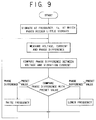
- the piezoelectric vibrating elements 5 of the parts feeder 1 are vibrated at a frequency, fa, which is lower than the actual driving frequency and at which the parts feeder 1 hardly vibrates, a voltage Va, a current Ia, and a phase difference ⁇ a therebetween are detected while the piezoelectric vibrating elemans are driven at that frequency.
- a driving voltage Vb and a driving current Ib are detected when the parts feeder 1 is actually vibrated.
- a vibration current component Ib 1 is obtained by calculation from the equations (2) and (3) mentioned above and a phase difference ⁇ b between the vibration current Ib 1 and the driving voltage Vb is computed.
- This phase difference ⁇ b is compared to a prescribed preset value. If it is found that the phase difference ⁇ b is smaller than the preset value, the driving frequency is increased, while if it is found that it is larger than the preset value, the frequency is reduced.
- the above controls are executed by making using the fact that the vibration of the piezoelectric vibrating element at a resonance point is delayed by 90 degrees in phase to the vibration of the driving current and is identical to a phase of the vibration current Ib 1 relating to the vibration.
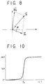
- a phase lag of displacement in the piezoelectric vibrating element to an exciting force F is generally in a relation as shown in Fig. 10, so that the phase is delayed by 90 degrees to the exciting force at the resonance point f 0 .
- the phase of the vibration current Ib 1 and the phase of the actual displacement in the piezoelectric vibrating element are identical to each other. Accordingly, by detecting the deviation of the phase and controlling a frequency of a driving signal, the piezoelectric vibrating element can always be driven at a resonance frequency.
- the peizoelectric vibrating element is of a self-excited vibration type
- an accurate vibration can be obtained if the phase of the vibration current Ib is designed to be delayed by 90 degrees in phase ( ⁇ shown in Fig. 8) to the phase of the driving current.
- the setting device 22 is used for setting an amplitude phase.
- a user sets a frequency at a prescribed value.
- an accurate phase control can also be performed by detecting a phase in the vibration current. Then the frequency is set by the setting device 22.
- an accurate frequency controi can also be performed, as is in the first embodiment, without using any complicated sensor.
- the present invention is not limited to the embodiments as described above.
- the present invention is generally applicable not only to a parts feeder but also to any apparatus using a piezoelectric vibrating element.
- the described embodiments are therefore to be considered in all respects as illustrative and not restrictive, the scope of the invention being indicated by the appended claims rather than by the foregoing description and all changes which come within the meaning and range of equivalency of the claims are, therefore, intended to be embraced therein.
Applications Claiming Priority (3)
| Application Number | Priority Date | Filing Date | Title |
|---|---|---|---|
| JP22584096 | 1996-08-07 | ||
| JP225840/96 | 1996-08-07 | ||
| JP22584096A JP3418507B2 (ja) | 1996-08-07 | 1996-08-07 | 圧電振動制御方法 |
Publications (3)
| Publication Number | Publication Date |
|---|---|
| EP0823680A2 true EP0823680A2 (de) | 1998-02-11 |
| EP0823680A3 EP0823680A3 (de) | 1998-04-22 |
| EP0823680B1 EP0823680B1 (de) | 2002-06-19 |
Family
ID=16835656
Family Applications (1)
| Application Number | Title | Priority Date | Filing Date |
|---|---|---|---|
| EP97305310A Expired - Lifetime EP0823680B1 (de) | 1996-08-07 | 1997-07-16 | Verfahren und Vorrichtung zur Regelung von piezoelektrischen Vibrationen |
Country Status (8)
| Country | Link |
|---|---|
| US (1) | US5910698A (de) |
| EP (1) | EP0823680B1 (de) |
| JP (1) | JP3418507B2 (de) |
| KR (1) | KR100249339B1 (de) |
| CN (1) | CN1146520C (de) |
| DE (1) | DE69713459T2 (de) |
| HK (1) | HK1008797A1 (de) |
| TW (1) | TW378288B (de) |
Cited By (1)
| Publication number | Priority date | Publication date | Assignee | Title |
|---|---|---|---|---|
| EP1179493A3 (de) * | 2000-08-11 | 2003-01-22 | Ykk Corporation | Verfahren und Vorrichtung zur Steuerung eines piezoelektrischen Schwingungsgebers |
Families Citing this family (21)
| Publication number | Priority date | Publication date | Assignee | Title |
|---|---|---|---|---|
| US5758637A (en) | 1995-08-31 | 1998-06-02 | Aerogen, Inc. | Liquid dispensing apparatus and methods |
| US6235177B1 (en) | 1999-09-09 | 2001-05-22 | Aerogen, Inc. | Method for the construction of an aperture plate for dispensing liquid droplets |
| US7971588B2 (en) | 2000-05-05 | 2011-07-05 | Novartis Ag | Methods and systems for operating an aerosol generator |
| US8336545B2 (en) | 2000-05-05 | 2012-12-25 | Novartis Pharma Ag | Methods and systems for operating an aerosol generator |
| JP2002128261A (ja) * | 2000-10-23 | 2002-05-09 | Ykk Corp | 電磁式パーツフィーダの制御方法と装置 |
| US6546927B2 (en) | 2001-03-13 | 2003-04-15 | Aerogen, Inc. | Methods and apparatus for controlling piezoelectric vibration |
| JP2002362723A (ja) | 2001-06-04 | 2002-12-18 | Ykk Corp | パーツフィーダの制御方法 |
| US7677467B2 (en) | 2002-01-07 | 2010-03-16 | Novartis Pharma Ag | Methods and devices for aerosolizing medicament |
| US7360536B2 (en) | 2002-01-07 | 2008-04-22 | Aerogen, Inc. | Devices and methods for nebulizing fluids for inhalation |
| JP4761709B2 (ja) | 2002-01-15 | 2011-08-31 | エアロジェン,インコーポレイテッド | エアロゾル発生器を作動するための方法およびシステム |
| ES2572770T3 (es) | 2002-05-20 | 2016-06-02 | Novartis Ag | Aparato para proporcionar pulverización para tratamiento médico y métodos |
| EP1367010A1 (de) | 2002-05-28 | 2003-12-03 | Ykk Corporation | Zuführeinrichtung und Steuerungsverfahren dafür |
| US7004306B2 (en) * | 2002-12-19 | 2006-02-28 | Fmc Technologies, Inc. | Conveying apparatus with piezoelectric driver |
| US8616195B2 (en) | 2003-07-18 | 2013-12-31 | Novartis Ag | Nebuliser for the production of aerosolized medication |
| US7946291B2 (en) | 2004-04-20 | 2011-05-24 | Novartis Ag | Ventilation systems and methods employing aerosol generators |
| US9108211B2 (en) | 2005-05-25 | 2015-08-18 | Nektar Therapeutics | Vibration systems and methods |
| US8373330B2 (en) * | 2009-01-13 | 2013-02-12 | Transonic Combustion, Inc. | Piezoelectric actuator employing switch |
| TWI544162B (zh) | 2013-08-05 | 2016-08-01 | 緯創資通股份有限公司 | 電子裝置的制振裝置及其制振方法 |
| CN107253063B (zh) * | 2017-07-25 | 2024-03-12 | 普莱斯(北京)科技有限公司 | 一种高效超声波加工装置 |
| DE112020000997B4 (de) | 2019-04-25 | 2024-01-11 | Murata Manufacturing Co., Ltd. | Pumpvorrichtung mit einer ersten und zweiten piezoelektrischen Pumpe mit unterschiedlichen Eingangsleistungen |
| TWM582398U (zh) * | 2019-05-16 | 2019-08-21 | 合世生醫科技股份有限公司 | Nebulizer |
Citations (6)
| Publication number | Priority date | Publication date | Assignee | Title |
|---|---|---|---|---|
| JPS5727808A (en) * | 1980-07-29 | 1982-02-15 | Yoshida Kogyo Kk <Ykk> | Amplitude control type parts feeder controller |
| US4677353A (en) * | 1983-09-27 | 1987-06-30 | Dresser Industries, Inc. | Electro-inductive vibratory monitoring system |
| US4952834A (en) * | 1988-03-14 | 1990-08-28 | Olympus Optical Co., Ltd. | Circuitry for driving ultrasonic motor |
| US5074403A (en) * | 1989-05-08 | 1991-12-24 | K-Tron Technologies, Inc. | Apparatus and method for two loop control of vibratory material feeders |
| US5372237A (en) * | 1992-08-24 | 1994-12-13 | Yoshida Kogyo K.K. | Control system for parts feeder |
| US5472079A (en) * | 1993-06-16 | 1995-12-05 | Yoshida Kogya K.K. | Method and apparatus for controlling the drive of self-excited vibrating parts feeder |
Family Cites Families (4)
| Publication number | Priority date | Publication date | Assignee | Title |
|---|---|---|---|---|
| CH672894A5 (de) * | 1987-09-14 | 1990-01-15 | Undatim Ultrasonics | |
| JP2618685B2 (ja) * | 1988-05-19 | 1997-06-11 | ティーディーケイ株式会社 | 圧電振動子駆動回路 |
| US4868445A (en) * | 1988-06-20 | 1989-09-19 | Wand Saul N | Self tuned ultrasonic generator system having wide frequency range and high efficiency |
| US4879528A (en) * | 1988-08-30 | 1989-11-07 | Olympus Optical Co., Ltd. | Ultrasonic oscillation circuit |
-
1996
- 1996-08-07 JP JP22584096A patent/JP3418507B2/ja not_active Expired - Fee Related
-
1997
- 1997-07-16 DE DE69713459T patent/DE69713459T2/de not_active Expired - Fee Related
- 1997-07-16 EP EP97305310A patent/EP0823680B1/de not_active Expired - Lifetime
- 1997-07-31 TW TW086110948A patent/TW378288B/zh not_active IP Right Cessation
- 1997-08-04 US US08/905,401 patent/US5910698A/en not_active Expired - Fee Related
- 1997-08-05 KR KR1019970037329A patent/KR100249339B1/ko not_active IP Right Cessation
- 1997-08-06 CN CNB971161615A patent/CN1146520C/zh not_active Expired - Fee Related
-
1998
- 1998-07-31 HK HK98109583A patent/HK1008797A1/xx not_active IP Right Cessation
Patent Citations (6)
| Publication number | Priority date | Publication date | Assignee | Title |
|---|---|---|---|---|
| JPS5727808A (en) * | 1980-07-29 | 1982-02-15 | Yoshida Kogyo Kk <Ykk> | Amplitude control type parts feeder controller |
| US4677353A (en) * | 1983-09-27 | 1987-06-30 | Dresser Industries, Inc. | Electro-inductive vibratory monitoring system |
| US4952834A (en) * | 1988-03-14 | 1990-08-28 | Olympus Optical Co., Ltd. | Circuitry for driving ultrasonic motor |
| US5074403A (en) * | 1989-05-08 | 1991-12-24 | K-Tron Technologies, Inc. | Apparatus and method for two loop control of vibratory material feeders |
| US5372237A (en) * | 1992-08-24 | 1994-12-13 | Yoshida Kogyo K.K. | Control system for parts feeder |
| US5472079A (en) * | 1993-06-16 | 1995-12-05 | Yoshida Kogya K.K. | Method and apparatus for controlling the drive of self-excited vibrating parts feeder |
Non-Patent Citations (1)
| Title |
|---|
| PATENT ABSTRACTS OF JAPAN vol. 006, no. 093 (M-133), 29 May 1982 & JP 57 027808 A (YOSHIDA KOGYO KK), 15 February 1982, * |
Cited By (1)
| Publication number | Priority date | Publication date | Assignee | Title |
|---|---|---|---|---|
| EP1179493A3 (de) * | 2000-08-11 | 2003-01-22 | Ykk Corporation | Verfahren und Vorrichtung zur Steuerung eines piezoelektrischen Schwingungsgebers |
Also Published As
| Publication number | Publication date |
|---|---|
| US5910698A (en) | 1999-06-08 |
| JP3418507B2 (ja) | 2003-06-23 |
| CN1182229A (zh) | 1998-05-20 |
| DE69713459T2 (de) | 2003-01-23 |
| DE69713459D1 (de) | 2002-07-25 |
| CN1146520C (zh) | 2004-04-21 |
| EP0823680B1 (de) | 2002-06-19 |
| HK1008797A1 (en) | 1999-05-21 |
| EP0823680A3 (de) | 1998-04-22 |
| TW378288B (en) | 2000-01-01 |
| KR19980018378A (ko) | 1998-06-05 |
| KR100249339B1 (ko) | 2000-03-15 |
| JPH1049237A (ja) | 1998-02-20 |
Similar Documents
| Publication | Publication Date | Title |
|---|---|---|
| US5910698A (en) | Method and apparatus for controlling piezoelectric vibration | |
| US6465932B2 (en) | Method and apparatus for controlling piezoelectric vibratory parts feeder | |
| US6050393A (en) | Drive apparatus for driving an oscillator and a powder feeder having the drive apparatus therein | |
| EP0629568B1 (de) | Verfahren und Vorrichtung zum Steuern des Antriebs von selbst-erregten Vibrationsförderern | |
| EP0161049A1 (de) | Drehgeschwindigkeitssensor | |
| US6776563B2 (en) | Method of controlling elliptical vibrator | |
| JP2019531994A (ja) | 振動供給装置及び振動供給装置の振動運動を調整する方法 | |
| US6994207B2 (en) | Driving unit for transducer | |
| JP2002362723A (ja) | パーツフィーダの制御方法 | |
| EP0533163B1 (de) | Vibrationskreisel | |
| JPH0595678U (ja) | 共振振動体の制御装置 | |
| CN110386423A (zh) | 振动系统的控制装置和工件输送装置 | |
| JP4524824B2 (ja) | 粉体供給装置 | |
| KR100198025B1 (ko) | 진동기의 구동제어장치 | |
| JP3641902B2 (ja) | 駆動装置 | |
| JPH02245277A (ja) | 圧電素子を用いた加振装置 | |
| JPH1151657A (ja) | 圧電振動式角速度センサの励振回路 | |
| JPS61287612A (ja) | 圧電駆動形搬送装置 | |
| SU1146921A1 (ru) | Установка дл ультразвукового упрочнени деталей | |
| JP2000180490A (ja) | 電位センサ | |
| JPH04182210A (ja) | 電磁振動フイーダ | |
| JPH08244945A (ja) | 圧電駆動型搬送装置 | |
| JPH0848413A (ja) | 振動機制御装置 | |
| JP2000131129A (ja) | 電磁フィーダ、計量装置および組合せ計量システム | |
| JPH03265474A (ja) | 定在波型振動波モータの駆動回路 |
Legal Events
| Date | Code | Title | Description |
|---|---|---|---|
| PUAI | Public reference made under article 153(3) epc to a published international application that has entered the european phase |
Free format text: ORIGINAL CODE: 0009012 |
|
| AK | Designated contracting states |
Kind code of ref document: A2 Designated state(s): DE FR GB IT |
|
| PUAL | Search report despatched |
Free format text: ORIGINAL CODE: 0009013 |
|
| AK | Designated contracting states |
Kind code of ref document: A3 Designated state(s): AT BE CH DE DK ES FI FR GB GR IE IT LI LU MC NL PT SE |
|
| 17P | Request for examination filed |
Effective date: 19980522 |
|
| AKX | Designation fees paid |
Free format text: DE FR GB IT |
|
| RBV | Designated contracting states (corrected) |
Designated state(s): DE FR GB IT |
|
| 17Q | First examination report despatched |
Effective date: 20000322 |
|
| GRAG | Despatch of communication of intention to grant |
Free format text: ORIGINAL CODE: EPIDOS AGRA |
|
| GRAG | Despatch of communication of intention to grant |
Free format text: ORIGINAL CODE: EPIDOS AGRA |
|
| GRAH | Despatch of communication of intention to grant a patent |
Free format text: ORIGINAL CODE: EPIDOS IGRA |
|
| GRAH | Despatch of communication of intention to grant a patent |
Free format text: ORIGINAL CODE: EPIDOS IGRA |
|
| GRAA | (expected) grant |
Free format text: ORIGINAL CODE: 0009210 |
|
| AK | Designated contracting states |
Kind code of ref document: B1 Designated state(s): DE FR GB IT |
|
| REG | Reference to a national code |
Ref country code: GB Ref legal event code: FG4D |
|
| REF | Corresponds to: |
Ref document number: 69713459 Country of ref document: DE Date of ref document: 20020725 |
|
| ET | Fr: translation filed | ||
| PLBE | No opposition filed within time limit |
Free format text: ORIGINAL CODE: 0009261 |
|
| STAA | Information on the status of an ep patent application or granted ep patent |
Free format text: STATUS: NO OPPOSITION FILED WITHIN TIME LIMIT |
|
| 26N | No opposition filed |
Effective date: 20030320 |
|
| PGFP | Annual fee paid to national office [announced via postgrant information from national office to epo] |
Ref country code: FR Payment date: 20090710 Year of fee payment: 13 |
|
| PGFP | Annual fee paid to national office [announced via postgrant information from national office to epo] |
Ref country code: GB Payment date: 20090715 Year of fee payment: 13 Ref country code: DE Payment date: 20090709 Year of fee payment: 13 |
|
| PGFP | Annual fee paid to national office [announced via postgrant information from national office to epo] |
Ref country code: IT Payment date: 20090717 Year of fee payment: 13 |
|
| GBPC | Gb: european patent ceased through non-payment of renewal fee |
Effective date: 20100716 |
|
| REG | Reference to a national code |
Ref country code: FR Ref legal event code: ST Effective date: 20110331 |
|
| PG25 | Lapsed in a contracting state [announced via postgrant information from national office to epo] |
Ref country code: DE Free format text: LAPSE BECAUSE OF NON-PAYMENT OF DUE FEES Effective date: 20110201 |
|
| REG | Reference to a national code |
Ref country code: DE Ref legal event code: R119 Ref document number: 69713459 Country of ref document: DE Effective date: 20110201 |
|
| PG25 | Lapsed in a contracting state [announced via postgrant information from national office to epo] |
Ref country code: FR Free format text: LAPSE BECAUSE OF NON-PAYMENT OF DUE FEES Effective date: 20100802 Ref country code: IT Free format text: LAPSE BECAUSE OF NON-PAYMENT OF DUE FEES Effective date: 20100716 |
|
| PG25 | Lapsed in a contracting state [announced via postgrant information from national office to epo] |
Ref country code: GB Free format text: LAPSE BECAUSE OF NON-PAYMENT OF DUE FEES Effective date: 20100716 |