EP0821198A1 - Sicherheitsvorrichtung eines Brenners zur Zündung der Flamme, Detektion der Flamme und Steuerung der Gaszufuhr - Google Patents
Sicherheitsvorrichtung eines Brenners zur Zündung der Flamme, Detektion der Flamme und Steuerung der Gaszufuhr Download PDFInfo
- Publication number
- EP0821198A1 EP0821198A1 EP97401757A EP97401757A EP0821198A1 EP 0821198 A1 EP0821198 A1 EP 0821198A1 EP 97401757 A EP97401757 A EP 97401757A EP 97401757 A EP97401757 A EP 97401757A EP 0821198 A1 EP0821198 A1 EP 0821198A1
- Authority
- EP
- European Patent Office
- Prior art keywords
- flame
- oscillator
- burner
- signal
- electrodes
- Prior art date
- Legal status (The legal status is an assumption and is not a legal conclusion. Google has not performed a legal analysis and makes no representation as to the accuracy of the status listed.)
- Granted
Links
Images


Classifications
-
- F—MECHANICAL ENGINEERING; LIGHTING; HEATING; WEAPONS; BLASTING
- F23—COMBUSTION APPARATUS; COMBUSTION PROCESSES
- F23N—REGULATING OR CONTROLLING COMBUSTION
- F23N5/00—Systems for controlling combustion
- F23N5/02—Systems for controlling combustion using devices responsive to thermal changes or to thermal expansion of a medium
- F23N5/12—Systems for controlling combustion using devices responsive to thermal changes or to thermal expansion of a medium using ionisation-sensitive elements, i.e. flame rods
- F23N5/123—Systems for controlling combustion using devices responsive to thermal changes or to thermal expansion of a medium using ionisation-sensitive elements, i.e. flame rods using electronic means
-
- F—MECHANICAL ENGINEERING; LIGHTING; HEATING; WEAPONS; BLASTING
- F23—COMBUSTION APPARATUS; COMBUSTION PROCESSES
- F23N—REGULATING OR CONTROLLING COMBUSTION
- F23N1/00—Regulating fuel supply
- F23N1/08—Regulating fuel supply conjointly with another medium, e.g. boiler water
-
- F—MECHANICAL ENGINEERING; LIGHTING; HEATING; WEAPONS; BLASTING
- F23—COMBUSTION APPARATUS; COMBUSTION PROCESSES
- F23N—REGULATING OR CONTROLLING COMBUSTION
- F23N2227/00—Ignition or checking
- F23N2227/02—Starting or ignition cycles
-
- F—MECHANICAL ENGINEERING; LIGHTING; HEATING; WEAPONS; BLASTING
- F23—COMBUSTION APPARATUS; COMBUSTION PROCESSES
- F23N—REGULATING OR CONTROLLING COMBUSTION
- F23N2227/00—Ignition or checking
- F23N2227/22—Pilot burners
-
- F—MECHANICAL ENGINEERING; LIGHTING; HEATING; WEAPONS; BLASTING
- F23—COMBUSTION APPARATUS; COMBUSTION PROCESSES
- F23N—REGULATING OR CONTROLLING COMBUSTION
- F23N2227/00—Ignition or checking
- F23N2227/36—Spark ignition, e.g. by means of a high voltage
-
- F—MECHANICAL ENGINEERING; LIGHTING; HEATING; WEAPONS; BLASTING
- F23—COMBUSTION APPARATUS; COMBUSTION PROCESSES
- F23N—REGULATING OR CONTROLLING COMBUSTION
- F23N2235/00—Valves, nozzles or pumps
- F23N2235/12—Fuel valves
- F23N2235/14—Fuel valves electromagnetically operated
-
- F—MECHANICAL ENGINEERING; LIGHTING; HEATING; WEAPONS; BLASTING
- F23—COMBUSTION APPARATUS; COMBUSTION PROCESSES
- F23N—REGULATING OR CONTROLLING COMBUSTION
- F23N2235/00—Valves, nozzles or pumps
- F23N2235/12—Fuel valves
- F23N2235/16—Fuel valves variable flow or proportional valves
-
- F—MECHANICAL ENGINEERING; LIGHTING; HEATING; WEAPONS; BLASTING
- F23—COMBUSTION APPARATUS; COMBUSTION PROCESSES
- F23N—REGULATING OR CONTROLLING COMBUSTION
- F23N2235/00—Valves, nozzles or pumps
- F23N2235/12—Fuel valves
- F23N2235/18—Groups of two or more valves
-
- F—MECHANICAL ENGINEERING; LIGHTING; HEATING; WEAPONS; BLASTING
- F23—COMBUSTION APPARATUS; COMBUSTION PROCESSES
- F23N—REGULATING OR CONTROLLING COMBUSTION
- F23N5/00—Systems for controlling combustion
- F23N5/20—Systems for controlling combustion with a time programme acting through electrical means, e.g. using time-delay relays
-
- F—MECHANICAL ENGINEERING; LIGHTING; HEATING; WEAPONS; BLASTING
- F23—COMBUSTION APPARATUS; COMBUSTION PROCESSES
- F23N—REGULATING OR CONTROLLING COMBUSTION
- F23N5/00—Systems for controlling combustion
- F23N5/24—Preventing development of abnormal or undesired conditions, i.e. safety arrangements
Definitions
- the present invention relates to a device intended to control safety functions around a burner, for example in a boiler or a water heater.
- Burners require safety devices to avoid on the one hand that the flame remains absent from the burner, this which prohibits the functioning of the thermal system and, on the other hand, that if the flame goes out, the gas continues to be diffused by the burner.
- the present invention intends to remedy these disadvantages of presenting an electronic device flame ignition on a burner, detection of said flame and gas intake control in the burner, whose consumption is so low that it can be supplied by electric batteries.
- the device which is the subject of the invention includes a positive safety electronic assembly, for lighting and controlling the flame of a burner.
- the device allows the ignition of a burner main using an ignition burner. He commands ignition of the main burner only when the flame is present at the ignition burner.
- Electronic assembly powered by batteries, sparks, checks presence of flame and positively feeds a solenoid valve which allows the admission of gas to the burner main. This assembly applies to the burner ignition with non-permanent ignition burner.
- the tension between the electrodes are used both to light a flame, producing a spark, and detecting the presence of flame.
- a flame ionizes the material between the electrodes and that this material ionized behaves electrically like a diode, i.e. that it allows the passage of electrons only in a direction.
- the signal leaving the control means is adapted to reduce the frequency of the oscillator when the signal coming out of the comparator is representative of the presence of a flame between said two electrodes.
- the outgoing signal from the control means is adapted to reduce the output voltage of the oscillator when the signal leaving the comparator is representative of the presence of a flame between said two electrodes.
- the electricity consumption of the device is very reduced since the ignition phase, which is the largest consumer of energy, is very short and then the operation of the device serves to test the operation of a heating system.
- one of the two electrodes is consisting of the burner.
- the comparator is a window oscillator comparator and a gas inlet means into the burner is controlled by the window oscillator comparator whose instructions input are given by resistors.
- the security of device operation is positive. Indeed, if the DC voltage at the electrode output is greater than a first predetermined value, the comparator detects device malfunction and stops admission gas in the burner. If the voltage continues at the output electrode is less than a second value predetermined, the comparator detects an absence of flame and does not admit gas into the burner. If the direct voltage at the electrode is between the two predetermined values, the comparator detects a presence of flame and admits gas into the burner.
- the energy necessary for the control of the gas inlet means is sufficient low so that a battery can power it for several months, in normal operation. Thanks to these characteristics, no connection to the mains is necessary and installation is greatly simplified since there is no longer any electrical installation to foresee.
- the invention also relates to a heating means, water heater or boiler, for example, characterized in that it includes a device as briefly described above.
- FIG. 1 shows a thermal installation 1, comprising a gas inlet 2, a fluid inlet 3, a fluid outlet 4 and a burner 5 connected to the inlet of gas 2 and thermally connected to a fluid circuit 6 from the fluid inlet 3 to the fluid outlet 4.
- An electronic circuit 7 is supplied by a power supply 8, is connected to a means of flame presence detection 11 placed near the output of an ignition burner 14, to an ignition means of flame 9 placed at the outlet of the ignition burner 14, at a gas inlet means 25 placed between the gas inlet 2 and the burner 5 and to a draw-off switch 13.
- the thermal installation 1 is, for example, consisting of a water heater or boiler, of types known.
- the burner 5 is suitable for mixing air with gas from gas inlet 2, via gas intake means 25, to ensure good combustion of the mixture thus formed and to evacuate the gases burned by a chimney 12.
- the burner 5 is of the type known.
- Main burner 5 is lit by a burner ignition 14 whose flame is lit by the means flame ignition 9 and on which the presence of a flame is detected by the flame detection means 11.
- the fluid for example water, which circulates between the fluid inlet 3, where it is at a given temperature, and the fluid outlet 4, where it was heated by the flame of the burner 5, then runs through a circuit which depends on thermal installation 1.
- the gas inlet 2 is either connected to a tank of gas, or connected to a gas distribution network.
- the electronic circuit 7 is presented, according to several embodiments in FIGS. 2, 3 and 5.
- the power supply 8 preferably comprises an electric battery or an electric accumulator. However, it can possibly be supplemented by the electrical sector.
- the flame presence detection means 11 placed near the outlet of the ignition burner 14 is adapted to emit a signal representative of the presence or the absence of a flame at the burner outlet 5.
- the flame ignition means 9 placed at the burner outlet ignition 14 is suitable for lighting a flame at the outlet of the burner 5.
- the gas inlet means 25 placed between the gas inlet and the burner 5 is suitable either to leave pass gas from gas inlet 2 to the burner 5, when open, or to prohibit this traffic, when closed.
- the drawing switch 13 is controlled by the water flow in circuit 6, according to techniques known which are not detailed here.
- the electronic circuit 7, which will now be described with reference to Figures 2, 3 and 5, controls the means flame ignition 9 and a gas inlet means 10 as a function of the signal leaving the detection means of flame 11.
- the switching power supplies 24 and 27 provide voltages higher than the voltage of the voltage source. In the event of a fault, the solenoid valve 25 cannot therefore be accidentally ordered.
- drawing switch at the top of the figure 2, represents a means of energizing the circuit Figure 2. It controls a drawing switch 13 (figure 1) which makes the ignition request.
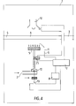
- FIGs 3 and 4 relate to an installation thermal where the main burner 5 is directly lit by the ignition means 9 and the flame on this burner is controlled by the flame detection means 11.
- circuit breaker 30 comprising two TR3 and TR4 transistors, associated resistors and a fuse F1, is connected to an input of the power supply 24.
- the circuit breaker 30 provides, together with a capacity C20 of the window oscillator comparator 23, the locking the device when the burner is not on before C20 capacity is charged up to the first predetermined value of the comparator oscillator 23, the system can only be unlocked by stopping the drawing.
- a power authorization circuit maximum 31 consisting of an operational amplifier IC2-e, receives the same signal as the comparator oscillator 23 and outputs a signal to the power supply to current regulated switching 27 whose diagram is simplified in Figure 3.
- the simplification of the switching power supply 27, shown in Figure 3 corresponds to a variant of electronic diagram of the power presented in figure 2.
- This variant has the advantage of being able to be connected to the mains.
- the burner 14 receives gas taken from the gas circuit upstream of the gas intake means 25.
- the electronic circuit 7 presented opposite the figure 5 is specifically adapted to the installation thermal 1 presented with reference to FIG. 6.
- Figure 6 shows a third type thermal installation incorporating a device according to the present invention, in which, in comparison with Figure 1, two solenoid valves 42 and 43 (presented in FIG. 5) replace the solenoid valve 25, and in which an electronic circuit 7, as presented in FIG. 5, controls said solenoid valves 42 and 43, depending on the electrical signals and switch positions corresponding to backflow protection, on request ignition or draw, and the ignition electrode.
- circuit IC2-c TR50 is used, 51, 61, D61, or another similar circuit for order the second solenoid valve or supply the current for the large valve.
- a comparator IC2-c which detects the passage of the signal flame at the voltage characteristic of a presence of flame and authorizes the operation of the second booster.
- the second booster (simplified in diagram 2) can be set to a fixed current or be controlled by a regulation system (see order of Vréf1 on diagram 1).
- the power supply circuit comprising the two switching power supplies 24 and 27 is suitable for applying between the terminals of the intake means of gas consisting of the solenoid valve 25, a voltage higher than the output voltage of the source power supply, so that a possible malfunction of said supply circuit prevents the gas passage through the gas inlet means.
Landscapes
- Engineering & Computer Science (AREA)
- Chemical & Material Sciences (AREA)
- Combustion & Propulsion (AREA)
- Mechanical Engineering (AREA)
- General Engineering & Computer Science (AREA)
- Control Of Combustion (AREA)
- Regulation And Control Of Combustion (AREA)
- Feeding And Controlling Fuel (AREA)
Applications Claiming Priority (2)
| Application Number | Priority Date | Filing Date | Title |
|---|---|---|---|
| FR9609371A FR2751729B1 (fr) | 1996-07-25 | 1996-07-25 | Dispositif de securisation de bruleur pour allumage de flamme, detection de flamme et commande d'admission de gaz |
| FR9609371 | 1996-07-25 |
Publications (2)
| Publication Number | Publication Date |
|---|---|
| EP0821198A1 true EP0821198A1 (de) | 1998-01-28 |
| EP0821198B1 EP0821198B1 (de) | 2001-12-12 |
Family
ID=9494474
Family Applications (1)
| Application Number | Title | Priority Date | Filing Date |
|---|---|---|---|
| EP97401757A Expired - Lifetime EP0821198B1 (de) | 1996-07-25 | 1997-07-22 | Sicherheitsvorrichtung eines Brenners zur Zündung der Flamme, Detektion der Flamme und Steuerung der Gaszufuhr |
Country Status (5)
| Country | Link |
|---|---|
| EP (1) | EP0821198B1 (de) |
| AT (1) | ATE210802T1 (de) |
| DE (1) | DE69708990T2 (de) |
| ES (1) | ES2169329T3 (de) |
| FR (1) | FR2751729B1 (de) |
Cited By (2)
| Publication number | Priority date | Publication date | Assignee | Title |
|---|---|---|---|---|
| US7944678B2 (en) | 2008-09-11 | 2011-05-17 | Robertshaw Controls Company | Low voltage power supply for spark igniter and flame sense |
| CN115077106A (zh) * | 2022-06-06 | 2022-09-20 | 宁波方太厨具有限公司 | 感应装置及燃气热水器 |
Families Citing this family (3)
| Publication number | Priority date | Publication date | Assignee | Title |
|---|---|---|---|---|
| CN100420901C (zh) * | 2006-07-21 | 2008-09-24 | 宁波方太厨具有限公司 | 一种具有意外熄火后自动再点火功能的燃气灶 |
| DE102017104526A1 (de) | 2017-03-03 | 2018-09-06 | Viessmann Werke Gmbh & Co Kg | Verfahren zur Bestimmung der Ursache einer Fehlzündung am Brenner eines Heizkessels |
| DE102019134702A1 (de) * | 2019-12-17 | 2021-06-17 | Rational Aktiengesellschaft | Gasbrennersystem, Gargerät und Verfahren zum Betreiben eines Gasbrennersystems |
Citations (8)
| Publication number | Priority date | Publication date | Assignee | Title |
|---|---|---|---|---|
| US3877864A (en) * | 1974-07-29 | 1975-04-15 | Itt | Spark igniter system for gas appliance pilot ignition |
| US3890579A (en) * | 1974-03-04 | 1975-06-17 | Itt | Ignition system and components thereof |
| US4145180A (en) * | 1977-11-29 | 1979-03-20 | Essex Group, Inc. | Ignition system for fuel burning apparatus |
| JPS56130533A (en) * | 1980-03-18 | 1981-10-13 | Matsushita Electric Ind Co Ltd | Combustion controller |
| JPS5733721A (en) * | 1980-08-09 | 1982-02-23 | Matsushita Electric Ind Co Ltd | Driving device for solenoid valve in combustion equipment |
| US4521180A (en) * | 1982-11-29 | 1985-06-04 | Kidde, Inc. | Laboratory burner apparatus |
| US4552528A (en) * | 1983-04-07 | 1985-11-12 | Societe Anonyme: Construction Electriques R.V. | Current generator for the supply and detection of operation of a gas burner and control device applying same |
| JPS62123222A (ja) * | 1985-11-25 | 1987-06-04 | Gasutaa:Kk | 燃焼安全装置 |
Family Cites Families (1)
| Publication number | Priority date | Publication date | Assignee | Title |
|---|---|---|---|---|
| FR2347620A1 (fr) * | 1976-07-15 | 1977-11-04 | Bicosa Recherches | Dispositif de detection de flamme ou d'etincelle et organe d'allumage d'un gaz combustible |
-
1996
- 1996-07-25 FR FR9609371A patent/FR2751729B1/fr not_active Expired - Fee Related
-
1997
- 1997-07-22 ES ES97401757T patent/ES2169329T3/es not_active Expired - Lifetime
- 1997-07-22 AT AT97401757T patent/ATE210802T1/de not_active IP Right Cessation
- 1997-07-22 DE DE69708990T patent/DE69708990T2/de not_active Expired - Fee Related
- 1997-07-22 EP EP97401757A patent/EP0821198B1/de not_active Expired - Lifetime
Patent Citations (8)
| Publication number | Priority date | Publication date | Assignee | Title |
|---|---|---|---|---|
| US3890579A (en) * | 1974-03-04 | 1975-06-17 | Itt | Ignition system and components thereof |
| US3877864A (en) * | 1974-07-29 | 1975-04-15 | Itt | Spark igniter system for gas appliance pilot ignition |
| US4145180A (en) * | 1977-11-29 | 1979-03-20 | Essex Group, Inc. | Ignition system for fuel burning apparatus |
| JPS56130533A (en) * | 1980-03-18 | 1981-10-13 | Matsushita Electric Ind Co Ltd | Combustion controller |
| JPS5733721A (en) * | 1980-08-09 | 1982-02-23 | Matsushita Electric Ind Co Ltd | Driving device for solenoid valve in combustion equipment |
| US4521180A (en) * | 1982-11-29 | 1985-06-04 | Kidde, Inc. | Laboratory burner apparatus |
| US4552528A (en) * | 1983-04-07 | 1985-11-12 | Societe Anonyme: Construction Electriques R.V. | Current generator for the supply and detection of operation of a gas burner and control device applying same |
| JPS62123222A (ja) * | 1985-11-25 | 1987-06-04 | Gasutaa:Kk | 燃焼安全装置 |
Non-Patent Citations (3)
| Title |
|---|
| PATENT ABSTRACTS OF JAPAN vol. 006, no. 010 (M - 107) 21 January 1982 (1982-01-21) * |
| PATENT ABSTRACTS OF JAPAN vol. 006, no. 101 (M - 135) 10 June 1982 (1982-06-10) * |
| PATENT ABSTRACTS OF JAPAN vol. 011, no. 344 (M - 640) 11 November 1987 (1987-11-11) * |
Cited By (3)
| Publication number | Priority date | Publication date | Assignee | Title |
|---|---|---|---|---|
| US7944678B2 (en) | 2008-09-11 | 2011-05-17 | Robertshaw Controls Company | Low voltage power supply for spark igniter and flame sense |
| CN115077106A (zh) * | 2022-06-06 | 2022-09-20 | 宁波方太厨具有限公司 | 感应装置及燃气热水器 |
| CN115077106B (zh) * | 2022-06-06 | 2024-03-08 | 宁波方太厨具有限公司 | 感应装置及燃气热水器 |
Also Published As
| Publication number | Publication date |
|---|---|
| FR2751729B1 (fr) | 1998-10-09 |
| FR2751729A1 (fr) | 1998-01-30 |
| ATE210802T1 (de) | 2001-12-15 |
| ES2169329T3 (es) | 2002-07-01 |
| DE69708990D1 (de) | 2002-01-24 |
| EP0821198B1 (de) | 2001-12-12 |
| DE69708990T2 (de) | 2002-08-01 |
Similar Documents
| Publication | Publication Date | Title |
|---|---|---|
| US5722823A (en) | Gas ignition devices | |
| FR2595134A1 (fr) | Bruleur a gaz a soufflage d'air force pour un poele a bois | |
| FR2536507A1 (fr) | Procede pour faire fonctionner un bruleur a gazeification pour carburant liquide, bruleur a gazeification et dispositif de commande pour la mise en oeuvre dudit procede | |
| FR2648217A1 (fr) | Dispositif de prechauffage de combustible, pour un atomiseur a ultrasons equipant des appareils de chauffage | |
| CH638603A5 (fr) | Appareil de commande de bruleur. | |
| EP0821199B1 (de) | Positive Sicherheitsvorrichtung der Gaszufuhr in einem Brenner | |
| EP0821198B1 (de) | Sicherheitsvorrichtung eines Brenners zur Zündung der Flamme, Detektion der Flamme und Steuerung der Gaszufuhr | |
| FR2490785A1 (fr) | Dispositif de commande de bruleur | |
| EP0020280B1 (de) | Sicherheitszündvorrichtung für ein Brennerventil | |
| US6653790B2 (en) | Automatic gas lamp with safety control circuit | |
| FR2686762A1 (fr) | Dispositif d'alimentation d'une lampe a decharge et projecteur de vehicule comportant un tel dispositif. | |
| EP0439417B1 (de) | Sicherheitsvorrichtung für einen Brennerbetrieb | |
| EP0024231A1 (de) | Steuervorrichtungen für Gasventile | |
| AU2004211485A1 (en) | Method and arrangement for igniting a gas flow | |
| FR2493962A1 (fr) | Bruleur pour combustible liquide comportant un detecteur d'oxygene place dans une flamme | |
| FR2852670A1 (fr) | Procede d'allumage d'un bruleur a huile et dispositif d'allumage destine a un groupe a bruleur a huile | |
| EP0023870B1 (de) | Sicherheitssteuervorrichtungen für Gasventile | |
| FR2602030A1 (fr) | Dispositif de commande pour la mise en marche du bruleur a gaz d'un chauffe-eau | |
| FR2493964A1 (fr) | Procede de controle de combustion catalytique d'un gaz et dispositif mettant en oeuvre ce procede | |
| JP3539040B2 (ja) | 燃焼装置 | |
| EP2063178A1 (de) | Elektronische Zündvorrichtung für Sauerstoff-Gas-Schweißgeräten | |
| FR2583856A1 (fr) | Circuit de coupure temporisee d'un bruleur a gaz | |
| JPH0668372B2 (ja) | 燃焼器具の制御回路 | |
| JPH09250741A (ja) | 燃焼装置 | |
| FI72594B (fi) | Likstroemsdriven styranordning foer en gasbraennare. |
Legal Events
| Date | Code | Title | Description |
|---|---|---|---|
| PUAI | Public reference made under article 153(3) epc to a published international application that has entered the european phase |
Free format text: ORIGINAL CODE: 0009012 |
|
| AK | Designated contracting states |
Kind code of ref document: A1 Designated state(s): AT BE CH DE DK ES FI FR GB GR IE IT LI LU MC NL PT SE |
|
| 17P | Request for examination filed |
Effective date: 19980703 |
|
| RBV | Designated contracting states (corrected) |
Designated state(s): AT BE DE ES FR GB NL |
|
| 17Q | First examination report despatched |
Effective date: 19991228 |
|
| GRAG | Despatch of communication of intention to grant |
Free format text: ORIGINAL CODE: EPIDOS AGRA |
|
| GRAG | Despatch of communication of intention to grant |
Free format text: ORIGINAL CODE: EPIDOS AGRA |
|
| GRAH | Despatch of communication of intention to grant a patent |
Free format text: ORIGINAL CODE: EPIDOS IGRA |
|
| GRAH | Despatch of communication of intention to grant a patent |
Free format text: ORIGINAL CODE: EPIDOS IGRA |
|
| GRAA | (expected) grant |
Free format text: ORIGINAL CODE: 0009210 |
|
| AK | Designated contracting states |
Kind code of ref document: B1 Designated state(s): AT BE DE ES FR GB NL |
|
| REF | Corresponds to: |
Ref document number: 210802 Country of ref document: AT Date of ref document: 20011215 Kind code of ref document: T |
|
| REG | Reference to a national code |
Ref country code: GB Ref legal event code: IF02 |
|
| REF | Corresponds to: |
Ref document number: 69708990 Country of ref document: DE Date of ref document: 20020124 |
|
| GBT | Gb: translation of ep patent filed (gb section 77(6)(a)/1977) |
Effective date: 20020314 |
|
| PGFP | Annual fee paid to national office [announced via postgrant information from national office to epo] |
Ref country code: BE Payment date: 20020701 Year of fee payment: 6 |
|
| REG | Reference to a national code |
Ref country code: ES Ref legal event code: FG2A Ref document number: 2169329 Country of ref document: ES Kind code of ref document: T3 |
|
| PGFP | Annual fee paid to national office [announced via postgrant information from national office to epo] |
Ref country code: ES Payment date: 20020704 Year of fee payment: 6 |
|
| PGFP | Annual fee paid to national office [announced via postgrant information from national office to epo] |
Ref country code: GB Payment date: 20020717 Year of fee payment: 6 |
|
| PGFP | Annual fee paid to national office [announced via postgrant information from national office to epo] |
Ref country code: AT Payment date: 20020725 Year of fee payment: 6 |
|
| PGFP | Annual fee paid to national office [announced via postgrant information from national office to epo] |
Ref country code: FR Payment date: 20020729 Year of fee payment: 6 |
|
| PGFP | Annual fee paid to national office [announced via postgrant information from national office to epo] |
Ref country code: NL Payment date: 20020731 Year of fee payment: 6 |
|
| PGFP | Annual fee paid to national office [announced via postgrant information from national office to epo] |
Ref country code: DE Payment date: 20020926 Year of fee payment: 6 |
|
| PLBE | No opposition filed within time limit |
Free format text: ORIGINAL CODE: 0009261 |
|
| STAA | Information on the status of an ep patent application or granted ep patent |
Free format text: STATUS: NO OPPOSITION FILED WITHIN TIME LIMIT |
|
| 26N | No opposition filed | ||
| PG25 | Lapsed in a contracting state [announced via postgrant information from national office to epo] |
Ref country code: GB Free format text: LAPSE BECAUSE OF NON-PAYMENT OF DUE FEES Effective date: 20030722 Ref country code: AT Free format text: LAPSE BECAUSE OF NON-PAYMENT OF DUE FEES Effective date: 20030722 |
|
| PG25 | Lapsed in a contracting state [announced via postgrant information from national office to epo] |
Ref country code: ES Free format text: LAPSE BECAUSE OF NON-PAYMENT OF DUE FEES Effective date: 20030723 |
|
| PG25 | Lapsed in a contracting state [announced via postgrant information from national office to epo] |
Ref country code: BE Free format text: LAPSE BECAUSE OF NON-PAYMENT OF DUE FEES Effective date: 20030731 |
|
| BERE | Be: lapsed |
Owner name: S.A. SAUNIER DUVAL EAU CHAUDE CHAUFFAGE *SDECC Effective date: 20030731 |
|
| PG25 | Lapsed in a contracting state [announced via postgrant information from national office to epo] |
Ref country code: NL Free format text: LAPSE BECAUSE OF NON-PAYMENT OF DUE FEES Effective date: 20040201 |
|
| PG25 | Lapsed in a contracting state [announced via postgrant information from national office to epo] |
Ref country code: DE Free format text: LAPSE BECAUSE OF NON-PAYMENT OF DUE FEES Effective date: 20040203 |
|
| GBPC | Gb: european patent ceased through non-payment of renewal fee |
Effective date: 20030722 |
|
| PG25 | Lapsed in a contracting state [announced via postgrant information from national office to epo] |
Ref country code: FR Free format text: LAPSE BECAUSE OF NON-PAYMENT OF DUE FEES Effective date: 20040331 |
|
| NLV4 | Nl: lapsed or anulled due to non-payment of the annual fee |
Effective date: 20040201 |
|
| REG | Reference to a national code |
Ref country code: FR Ref legal event code: ST |
|
| REG | Reference to a national code |
Ref country code: ES Ref legal event code: FD2A Effective date: 20030723 |