EP0821147B1 - Motorbremsvorrichtung für eine Brennkraftmaschine mit Turbolader - Google Patents
Motorbremsvorrichtung für eine Brennkraftmaschine mit Turbolader Download PDFInfo
- Publication number
- EP0821147B1 EP0821147B1 EP97109811A EP97109811A EP0821147B1 EP 0821147 B1 EP0821147 B1 EP 0821147B1 EP 97109811 A EP97109811 A EP 97109811A EP 97109811 A EP97109811 A EP 97109811A EP 0821147 B1 EP0821147 B1 EP 0821147B1
- Authority
- EP
- European Patent Office
- Prior art keywords
- exhaust
- turbine
- partition
- accordance
- motor brake
- Prior art date
- Legal status (The legal status is an assumption and is not a legal conclusion. Google has not performed a legal analysis and makes no representation as to the accuracy of the status listed.)
- Expired - Lifetime
Links
- 238000002485 combustion reaction Methods 0.000 title claims description 16
- 238000005192 partition Methods 0.000 claims description 40
- 230000001105 regulatory effect Effects 0.000 claims description 2
- 230000002093 peripheral effect Effects 0.000 claims 1
- 239000007789 gas Substances 0.000 description 25
- 238000011144 upstream manufacturing Methods 0.000 description 3
- 238000013461 design Methods 0.000 description 2
- 241000554155 Andes Species 0.000 description 1
- 230000001133 acceleration Effects 0.000 description 1
- 238000013459 approach Methods 0.000 description 1
- 238000004140 cleaning Methods 0.000 description 1
- 230000000694 effects Effects 0.000 description 1
- 238000002474 experimental method Methods 0.000 description 1
- 230000002349 favourable effect Effects 0.000 description 1
- 238000010304 firing Methods 0.000 description 1
- 239000012530 fluid Substances 0.000 description 1
- 238000002347 injection Methods 0.000 description 1
- 239000007924 injection Substances 0.000 description 1
- 238000009434 installation Methods 0.000 description 1
- 238000004519 manufacturing process Methods 0.000 description 1
- 238000012986 modification Methods 0.000 description 1
- 230000004048 modification Effects 0.000 description 1
- 238000012544 monitoring process Methods 0.000 description 1
- XLYOFNOQVPJJNP-UHFFFAOYSA-N water Substances O XLYOFNOQVPJJNP-UHFFFAOYSA-N 0.000 description 1
Images

Classifications
-
- F—MECHANICAL ENGINEERING; LIGHTING; HEATING; WEAPONS; BLASTING
- F02—COMBUSTION ENGINES; HOT-GAS OR COMBUSTION-PRODUCT ENGINE PLANTS
- F02B—INTERNAL-COMBUSTION PISTON ENGINES; COMBUSTION ENGINES IN GENERAL
- F02B37/00—Engines characterised by provision of pumps driven at least for part of the time by exhaust
- F02B37/02—Gas passages between engine outlet and pump drive, e.g. reservoirs
- F02B37/025—Multiple scrolls or multiple gas passages guiding the gas to the pump drive
-
- F—MECHANICAL ENGINEERING; LIGHTING; HEATING; WEAPONS; BLASTING
- F01—MACHINES OR ENGINES IN GENERAL; ENGINE PLANTS IN GENERAL; STEAM ENGINES
- F01D—NON-POSITIVE DISPLACEMENT MACHINES OR ENGINES, e.g. STEAM TURBINES
- F01D17/00—Regulating or controlling by varying flow
- F01D17/10—Final actuators
- F01D17/12—Final actuators arranged in stator parts
- F01D17/14—Final actuators arranged in stator parts varying effective cross-sectional area of nozzles or guide conduits
- F01D17/148—Final actuators arranged in stator parts varying effective cross-sectional area of nozzles or guide conduits by means of rotatable members, e.g. butterfly valves
-
- F—MECHANICAL ENGINEERING; LIGHTING; HEATING; WEAPONS; BLASTING
- F02—COMBUSTION ENGINES; HOT-GAS OR COMBUSTION-PRODUCT ENGINE PLANTS
- F02B—INTERNAL-COMBUSTION PISTON ENGINES; COMBUSTION ENGINES IN GENERAL
- F02B37/00—Engines characterised by provision of pumps driven at least for part of the time by exhaust
- F02B37/12—Control of the pumps
- F02B37/18—Control of the pumps by bypassing exhaust from the inlet to the outlet of turbine or to the atmosphere
-
- F—MECHANICAL ENGINEERING; LIGHTING; HEATING; WEAPONS; BLASTING
- F02—COMBUSTION ENGINES; HOT-GAS OR COMBUSTION-PRODUCT ENGINE PLANTS
- F02B—INTERNAL-COMBUSTION PISTON ENGINES; COMBUSTION ENGINES IN GENERAL
- F02B37/00—Engines characterised by provision of pumps driven at least for part of the time by exhaust
- F02B37/12—Control of the pumps
- F02B37/22—Control of the pumps by varying cross-section of exhaust passages or air passages, e.g. by throttling turbine inlets or outlets or by varying effective number of guide conduits
-
- F—MECHANICAL ENGINEERING; LIGHTING; HEATING; WEAPONS; BLASTING
- F02—COMBUSTION ENGINES; HOT-GAS OR COMBUSTION-PRODUCT ENGINE PLANTS
- F02D—CONTROLLING COMBUSTION ENGINES
- F02D9/00—Controlling engines by throttling air or fuel-and-air induction conduits or exhaust conduits
- F02D9/04—Controlling engines by throttling air or fuel-and-air induction conduits or exhaust conduits concerning exhaust conduits
- F02D9/06—Exhaust brakes
-
- Y—GENERAL TAGGING OF NEW TECHNOLOGICAL DEVELOPMENTS; GENERAL TAGGING OF CROSS-SECTIONAL TECHNOLOGIES SPANNING OVER SEVERAL SECTIONS OF THE IPC; TECHNICAL SUBJECTS COVERED BY FORMER USPC CROSS-REFERENCE ART COLLECTIONS [XRACs] AND DIGESTS
- Y02—TECHNOLOGIES OR APPLICATIONS FOR MITIGATION OR ADAPTATION AGAINST CLIMATE CHANGE
- Y02T—CLIMATE CHANGE MITIGATION TECHNOLOGIES RELATED TO TRANSPORTATION
- Y02T10/00—Road transport of goods or passengers
- Y02T10/10—Internal combustion engine [ICE] based vehicles
- Y02T10/12—Improving ICE efficiencies
Definitions
- the invention relates to an engine brake device for a Internal combustion engine according to the preamble of claim 1.
- US 3,009,320 discloses a starting device for one Turbine engine, one directed at a turbine wheel Nozzle has a tapered channel.
- a motor brake for one an internal combustion engine provided with an exhaust gas turbocharger in the exhaust pipe between the engine and turbine an exhaust gas shut-off device is provided for a turbocharger is.
- This is a rotary valve with a swivel Valve body formed, the axis of which is perpendicular to the Exhaust pipe is arranged.
- This exhaust valve can be arranged in an open position in which the exhaust gases reach the turbine of the turbocharger unhindered. In a Closed position of the rotary valve can still be a residual current Exhaust gas get to the turbine of the turbocharger through which a Turbine wheel of the turbine is driven.
- an engine brake device is known from US Pat. No. 3,591,959 known for an internal combustion engine in which between an engine and an exhaust gas turbocharger Exhaust shut-off device is provided with which a front and rear exhaust manifold of a 6-cylinder internal combustion engine is lockable.
- the invention is therefore based on the object Engine brake device for an internal combustion engine with a Exhaust gas turbocharger to create, in which the braking power lower temperature load on the engine and exhaust pipe is increased.
- a arranged in front of an exhaust gas shut-off device branching bypass line in an area near a Turbine wheel opens, has the advantage that the Air masses fed to turbine wheel under high flow velocity are supplied, causing the turbocharger speed compared to the closed exhaust shut-off device does not approach zero from the prior art.
- This can be compared to that of the prior art
- Known exhaust gas shutoff device at least one The same braking power with a lower temperature load in the internal combustion engine and the exhaust pipe be achieved. This arrangement has shown in experiments that thereby even a significant increase in braking performance the compressed air that is fed to the internal combustion engine will be realized.
- the bypass line over the air masses at least one at the end of a partition of a turbine housing arranged nozzle opening a radial ring channel of the turbine feeds.
- This arrangement concerns multi-flow, in particular double-flow, radial turbines. This allows the air masses fed close to the turbine wheel and a high one Turbine wheel efficiency can be achieved.
- a multi-flow Radial turbine partition channels are provided, each communicate with a nozzle opening.
- an annular space is provided in the partition which extends to the nozzle openings.
- the or the partition channels and or taper the annular spaces to the free end of the partition and the adjoining nozzle channels on their Nozzle openings have the narrowest cross-section.
- the feeding of the Air mass is advantageously carried out via thin Pipelines.
- the air masses are under high pressure and can through the nozzle openings in front of the turbine wheel with a emerge at high flow rates.
- the pressures that for example, can be above 50 bar, cause the Flow velocities despite the small Flow cross sections in the feed lines are relatively small and so are low loss.
- the turbine can operate in this mode as a pure impulse turbine analogous to the Pelton constant pressure turbine work.
- it can be provided that with separate Individual nozzles or supply of air masses via certain A high partial loading is made possible for the nozzle openings. This can be done by firing the engine or opening the engine Control valves in the cylinder for the individual nozzle openings take place and thus a phased use of the feeder the air masses determined through the individual nozzle openings become.
- the nozzle channel and the nozzle opening in a flat relative to the circumferential direction of the turbine wheel Exit angle is arranged. This can be achieved that with simultaneous action on the two Flow channels and the nozzles in the partition Flow angles can be almost identical because of the over the Air masses supplied to flow channels due to the high Flow velocities are accelerated with the Air masses occur from the nozzle openings. Thus a high turbine output can be achieved by the large Swirl component of the flow can be given.
- the nozzle openings essentially are arranged tangentially to the turbine wheel. This will make the swirl-shaped inflow achieved. This will make the Turbine output increased and a higher air mass flow enables.
- the exhaust gas shut-off device and at least the branch of the bypass line in the turbine housing are integrated. This can minimize components be given. This also leads to faster assembly, there assembly and installation of the exhaust gas shut-off device a branch in the exhaust pipe can fail to appear.
- an engine 10 is a multi-cylindrical Internal combustion engine shown.
- a first intake line 11 leads air masses to a compressor 12 of an exhaust gas turbocharger 13 to.
- the air mass is compressed and a second Compressor pressure line 14 to the combustion chamber of engine 10 fed.
- Exhaust line 16 is provided, which flows into a flow channel 17 a turbine 18 of the exhaust gas turbocharger 13 leads.
- Over a Second exhaust line 19 downstream of the turbine 18 becomes the exhaust gas via an exhaust gas cleaning system (not shown) to the outside guided.
- an engine brake device 21 On the exhaust side of the engine 10 is an engine brake device 21 provided an exhaust gas shut-off device 22 and an upstream of the exhaust gas shutoff device 22 has branching bypass line 23. Parallel to that Exhaust shut-off device 22 is a blow-off device 24 arranged with a first connecting line 26 is coupled. With the signal line 25 Blow-off device regulated. Depending on the required Braking performance can be the relief valve, which is an accurate Dosing the amount of air allows to be opened. The Blow off device also comes to the task of Overload protection too. From a given maximum Pressure behind the exhaust valves, the relief valve Opening controlled. The line 27a downstream of the Blow-off valve 24 opens into line 19. It would also be possible alternatively, a line 27b which runs in the turbine spiral 17 ends.
- the exhaust gas shut-off device 22 is a brake flap, preferably designed as a butterfly valve.
- the Brake flap 22 corresponds to the cross section of the exhaust pipe 16, so that this the exhaust pipe 16 in the sliding or Braking completely closes. This builds up this brake flap 22 has an exhaust gas pressure.
- the pent up Masses of air thereby flow into the bypass line 23, which is close of the turbine wheel 28 opens into the flow channel 17.
- the turbine speed can be kept high, thereby the compressor wheel, which is forcibly connected via a shaft 29 31 compresses the intake air and supplies it to the engine 10.
- there is an increased air mass flow rate in this system given causing the temperature of the air behind the engine can be held down.
- the one connected to the exhaust gas shutoff device 22 Blow-off device 24 is used as a metering and pressure relief valve educated. This is the maximum dynamic pressure before Exhaust shut-off device 22 can be limited. This pressure limitation has the advantage that monitoring may be excessive is given. In addition, this offers Pressure relief valve a design option for an increase of the boost pressure at low engine speeds. With the help of a The intelligent regulation of the relief valve can Influence the braking characteristics of the motor.
- the pressure relief valve opens so that the accumulated air masses over the first and second Connection line 26, 27a or 27b in the second Exhaust pipe 19 or turbine spiral 17 can flow out.
- the bypass line 23 has a not shown Distributor on, all arranged in the housing 32 Nozzle openings 33 supplied. Alternatively, it can be provided that instead of the nozzle openings 33, a guide grill in the Housing 32 is provided. Due to the tangential arrangement of the nozzle openings 33, which are, for example, 10 ° with respect to the Entry surface 36 can be arranged, the Masses of air supplied swirling. This can result in a high Turbine output or turbine speed can be achieved that in turn causes a high air throughput of the engine 10.
- the nozzle openings 33 practically represent the brake gap, the brake flap gap known from the prior art with a defined size for approved engine back pressures essentially corresponds.
- the sum of the nozzle opening cross sections is of the order of magnitude of a Airbrake gap of the exhaust shut-off device 22, which from the State of the art is known.
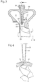
- Fig. 2 is a schematic section of a double flow Exhaust gas turbocharger 13 shown.
- the housing 23 has one the partition 51 separating the flow channels 17.
- a partition channel 52 is provided on the a bypass line 23 can be connected.
- a nozzle 54 arranged at a free end 53 of the partition 51 near the turbine wheel 28.
- the nozzle 54 points directly to the Partition duct 52 adjoining nozzle duct 56, the one has nozzle opening 33 facing turbine wheel 28.
- the Nozzle opening 33 is at a flat exit angle to the Turbine wheel 28 arranged, as shown in Fig. 3.
- the air mass supplied via the bypass line 23 can thus essentially tangentially into the radial ring channel 34 flow in and onto the blades 37 of the turbine wheel 28 to meet.
- the Nozzle ring 57 can be manufactured as a separate component. This allows the manufacturing accuracy of the Nozzle ring 57, very high requirements due of the extremely small nozzle channels 56 and nozzle openings 57 and their strong influences on the system behavior of the turbine 18 are met. Alternatively, it can be provided that the Nozzle channels 56 and nozzle openings 33 in one piece with the Partition 51 are formed.
- the bypass lines 23 have a small cross section, wherein the cross section of the bypass line 23 downstream the partition duct 52 and the nozzle duct 56 to Taper nozzle opening 33 continuously. This can achieved that the flow rates despite the small flow cross sections in the feeds relative low and thus low-loss, due to of the expansion cross section immediately after the nozzle opening 33 close to the turbine wheel due to the heights Pressure ratios supersonic speeds for the Air masses can result even at relatively small Turbine efficiencies result in high turbine performance.
- an annular channel or an annular space is provided instead of one or more partition channels 52 in the partition 51 .
- This can the air mass evenly over the circumference of the partition 51 flow in, at the free end 53 of the partition 51 also a nozzle ring channel with individual nozzles can be provided.
- the nozzle ring 57 with the nozzles 54 distributed over the circumference can alternatively be designed as a guide grill, whereby the Air mass also deflected analogously to the nozzles 54 and below a flat exit angle in the radial ring channel 34 close of the turbine wheel 28 can flow.
- Fig. 2 and Fig. 3 as also the alternative embodiment with a ring channel and the guide screen assigned to the partition 51 can also be used multi-flow turbocharger radial turbines used become.
- both Individual nozzles 54, a nozzle ring 57 or a guide vane on one free end 53 of the partition 51 may be provided, both individual partition channels 52 and an annular space exhibit.
- Such an additional supply of Air masses over the partition 51 immediately before that Turbine wheel 28 in the radial ring channel 34 can in particular be used in so-called turbo brake systems, because an increase in temperature can be reduced here.
- a nozzle arrangement described for FIGS. 2 and 3 on free end 53 of a partition 51 can have a high charge enable the internal combustion engine, for example during the braking phase by a more energetically favorable Loss behavior of the gas after the cylinder up to Turbine wheel 28 for the implementation of work within the turbine 18. This is because the compressor 12 requires Air mass directly related to the exploitation of the Internal combustion engine released exergy in the turbine 18 and stands for the amount of achievable braking power. Next Such a modification can be used in braking operation the turbine 18 can also be used as an acceleration aid.
- a high-pressure tract in front of the turbine wheel 28 also to increase the power of the turbine 18 additional water injection, e.g. emergency braking, be used.
- additional water injection e.g. emergency braking
- the Bypass lines 23 to the partition duct 52 from relative large-volume exhaust manifolds can be arranged independently can, so that these are small in cross section Bypass lines 23 for a targeted and metered Transport of any fluids to the turbine 18 or subsequent converters and filters advantageously let insert.
Landscapes
- Engineering & Computer Science (AREA)
- Mechanical Engineering (AREA)
- General Engineering & Computer Science (AREA)
- Chemical & Material Sciences (AREA)
- Combustion & Propulsion (AREA)
- Supercharger (AREA)
Description
- Fig. 1
- eine schematische Darstellung der erfindungsgemäßen Anordnung einer Bremsvorrichtung,
- Fig. 2
- eine Ausführungsform einer zweiflutigen Radialturbine und
- Fig. 3
- eine schematische Seitenansicht entlang der Linie V-V in Fig. 2.
Claims (12)
- Motorbremsvorrichtung für eine Brennkraftmaschine, die einen Abgasturbolader (13) mit einer Turbine (18) und einem Verdichter (12) sowie eine Abgasleitung (16, 19) und eine Ansaugleitung (11, 14) aufweist und mit mindestens einer stromauf der Turbine (18) in der Abgasleitung (16) angeordneten Abgasabsperrvorrichtung (22), wobei stromauf der Abgasabsperrvorrichtung (22) zumindest eine von der Abgasleitung (16, 19) abführende Bypassleitung (23) vorgesehen ist, die in einem Bereich nahe eines Turbinenrades (28) einmündet, wobei eine die Bypassleitung (23) durchströmende Luftmasse über zumindest eine am freien Ende (53) einer Trennwand (51) einer mehrflutigen Turbine (18) angeordneten Düsenöffnung (33) einem Radialringkanal (34) der Turbine (18) zugeführt wird, wobei in der Trennwand (51) zumindest ein Trennwandkanal (52) angeordnet ist, der jeweils in die Düsenöffnung (33) mündet, dadurch gekennzeichnet, daß der zumindest eine Kanal (52) zur Düsenöffnung (33) verjüngend ausgebildet ist und die Düsenöffnung (33) den engsten Querschnitt aufweist, wobei am freien Ende (53) der Trennwand (51) ein Düsenring (57) mit zumindest einem eine Düse (54) bildenden Düsenkanal (56) und Düsenöffnung (33) vorgesehen und der Düsenkanal (56) zur Düsenöffnung (33) verjüngend ausgebildet ist oder daß am freien Ende (53) der Trennwand (51) ein Leitgitter angeordnet ist.
- Motorbremsvorrichtung nach Anspruch 1, dadurch gekennzeichnet, daß in der Trennwand (51) ein Ringraum vorgesehen ist, der sich bis zu der zumindest einen Düsenöffnung (33) erstreckt.
- Motorbremsvorrichtung nach Anspruch 1 oder 2, dadurch gekennzeichnet, daß an jedem in der Trennwand (51) zugeordneten Trennwandkanal (52) eine Düse (54) angeordnet ist.
- Motorbremsvorrichtung nach einem der Ansprüche 1 bis 3, dadurch gekennzeichnet, daß die Düsenöffnung (33) zur Trennwand (51) relativ zur Umfangsrichtung des Turbinenrades (28) einen flachen Austrittswinkel aufweist.
- Motorbremsvorrichtung nach einem der Ansprüche 1 bis 4, dadurch gekennzeichnet, daß die Summe der Querschnittsfläche der Düsenöffnungen (33) zumindest einer definierten Größe eines Bremsklappenspaltes für einen zugelassenen Motorgegendruck eines Abgasabsperrventils (22) entspricht.
- Motorbremsvorrichtung nach einem der vorhergehenden Ansprüche, dadurch gekennzeichnet, daß zumindest die Abgasabsperrvorrichtung (22) und der zumindest eine stromauf der Abgasabsperrvorrichtung (22) angeordnete Abzweig für die Bypassleitung (23) in dem Gehäuse (32) der Turbine (28) angeordnet sind.
- Motorbremsvorrichtung nach einem der vorhergehenden Ansprüche, dadurch gekennzeichnet, daß zumindest die Abgasabsperrvorrichtung (22) über eine Verbindungsleitung (26) mit einer Abblasevorrichtung (24) in Verbindung steht, dessen stromab angeordnete Verbindungsleitung (27a bzw. 27b) in die Abgasleitung (19) bzw. Turbinenspirale (17) einmündet.
- Motorbremsvorrichtung nach Anspruch 7, dadurch gekennzeichnet, daß die Abblasevorrichtung (24) als Überdruckventil ausgebildet ist und auf einen maximalen Staudruck vor der Abgasabsperrvorrichtung (22) einstellbar ist.
- Motorbremsvorrichtung nach Anspruch 7 oder 8, dadurch gekennzeichnet, daß das Abblaseventil (24) über eine Regelungseinrichtung (25) angesteuert wird.
- Motorbremsvorrichtung nach einem der Ansprüche 7 bis 9, dadurch gekennzeichnet, daß die Abblasevorrichtung (24) mit einem Motormanagement kennfeldgeregelt ansteuerbar ist.
- Motorbremsvorrichtung nach einem der Ansprüche 7 bis 10, dadurch gekennzeichnet, daß mit einer elektronischen Regelung einer Ventilstellung der Abblasevorrichtung (24) bei vollständig geschlossener Abgasabsperrvorrichtung (22) die Bremscharakteristik des Motors (10) veränderbar ist.
- Motorbremsvorrichtung nach einem der vorhergehenden Ansprüche, dadurch gekennzeichnet, daß die Abgasleitung (16) in einer Schließstellung der Abgasabsperrvorrichtung (22) im wesentlichen vollständig absperrbar ist.
Applications Claiming Priority (2)
| Application Number | Priority Date | Filing Date | Title |
|---|---|---|---|
| DE19630224A DE19630224A1 (de) | 1996-07-26 | 1996-07-26 | Motorbremsvorrichtung |
| DE19630224 | 1996-07-26 |
Publications (2)
| Publication Number | Publication Date |
|---|---|
| EP0821147A1 EP0821147A1 (de) | 1998-01-28 |
| EP0821147B1 true EP0821147B1 (de) | 2000-05-10 |
Family
ID=7800947
Family Applications (1)
| Application Number | Title | Priority Date | Filing Date |
|---|---|---|---|
| EP97109811A Expired - Lifetime EP0821147B1 (de) | 1996-07-26 | 1997-06-17 | Motorbremsvorrichtung für eine Brennkraftmaschine mit Turbolader |
Country Status (3)
| Country | Link |
|---|---|
| US (1) | US6101812A (de) |
| EP (1) | EP0821147B1 (de) |
| DE (2) | DE19630224A1 (de) |
Cited By (1)
| Publication number | Priority date | Publication date | Assignee | Title |
|---|---|---|---|---|
| AT502997B1 (de) * | 2005-12-20 | 2013-09-15 | Man Truck & Bus Oesterreich Ag | Vorrichtung zur steigerung der bremsleistung einer mehrzylindrigen brennkraftmaschine eines fahrzeugs während des motorbremsbetriebes |
Families Citing this family (13)
| Publication number | Priority date | Publication date | Assignee | Title |
|---|---|---|---|---|
| US20090205329A1 (en) * | 2002-04-01 | 2009-08-20 | Niket Patwardhan | Heat engine matched to cheap heat source or sink |
| US7150151B2 (en) * | 2002-11-19 | 2006-12-19 | Cummins Inc. | Method of controlling the exhaust gas temperature for after-treatment systems on a diesel engine using a variable geometry turbine |
| DE10260779A1 (de) * | 2002-12-23 | 2004-07-01 | Daimlerchrysler Ag | Abgasturbolader |
| US7644585B2 (en) * | 2004-08-31 | 2010-01-12 | The United States Of America As Represented By The Administrator Of The U.S. Environmental Protection Agency | Multi-stage turbocharging system with efficient bypass |
| EP1762716B1 (de) * | 2005-09-07 | 2012-11-21 | BorgWarner, Inc. | Bremsklappe mit Bypass |
| US20120159947A1 (en) * | 2009-02-19 | 2012-06-28 | Volvo Lastvagnar Ab | Method and apparatus for controlling turbine efficiency |
| AT510236B1 (de) * | 2010-07-26 | 2015-12-15 | MAN Truck & Bus Österreich AG | Verfahren zur motorbremsung |
| AT510237B1 (de) | 2010-07-26 | 2015-12-15 | MAN Truck & Bus Österreich AG | Verfahren zur motorbremsung |
| DE102010053057A1 (de) * | 2010-12-01 | 2012-06-06 | Daimler Ag | Aufladeeinrichtung für eine Verbrennungskraftmaschine |
| DE102012100339A1 (de) * | 2012-01-16 | 2013-07-18 | Universität der Bundeswehr München | Verfahren und Vorrichtung zur Stabilisierung eines Verdichterstroms |
| AT512567B1 (de) * | 2012-03-01 | 2014-03-15 | Man Truck & Bus Oesterreich Ag | Funktionsmodul mit einem Abgasturbolader und einem Abgaskrümmer |
| CN106438058A (zh) * | 2016-12-07 | 2017-02-22 | 东风商用车有限公司 | 一种带排气制动碟阀的发动机排气管 |
| CN114824363B (zh) * | 2022-04-27 | 2024-04-30 | 杭州氢磁机电科技有限公司 | 集成有引射器的氢气循环泵 |
Citations (1)
| Publication number | Priority date | Publication date | Assignee | Title |
|---|---|---|---|---|
| US3009320A (en) * | 1959-06-15 | 1961-11-21 | Gen Electric | Fluid impingement starter for turbine engines |
Family Cites Families (8)
| Publication number | Priority date | Publication date | Assignee | Title |
|---|---|---|---|---|
| AT279275B (de) * | 1968-08-07 | 1970-02-25 | Maschf Augsburg Nuernberg Ag | Abgasdrossel für Auspuffbremsen an aufgeladenen Verbrennungsmotoren |
| US4138849A (en) * | 1977-06-06 | 1979-02-13 | Cummins Engine Company, Inc. | Exhaust braking valve |
| DE3504465C1 (de) * | 1985-02-09 | 1986-01-02 | M.A.N.-B & W Diesel GmbH, 8900 Augsburg | Vorrichtung zum Aufladen eines Verbrennungsmotors |
| DE3610131A1 (de) * | 1986-03-26 | 1987-09-17 | Bayerische Motoren Werke Ag | Brennkraftmaschine, insbesondere dieselmotor, als antriebseinrichtung fuer fahrzeuge |
| DE3935367A1 (de) * | 1989-10-24 | 1991-04-25 | Daimler Benz Ag | Verfahren zum betreiben einer motorbremse fuer brennkraftmaschinen, insbesondere von fahrzeugen, und nach diesem verfahren betriebene motorbremse |
| JP2959143B2 (ja) * | 1991-01-31 | 1999-10-06 | いすゞ自動車株式会社 | 発電・電動機を持つターボチャージャ |
| JPH06278595A (ja) * | 1993-03-29 | 1994-10-04 | Jidosha Kiki Co Ltd | エキゾーストブレーキバルブ装置 |
| DE19540060A1 (de) * | 1995-10-27 | 1997-04-30 | Daimler Benz Ag | Motorbremsvorrichtung |
-
1996
- 1996-07-26 DE DE19630224A patent/DE19630224A1/de not_active Withdrawn
-
1997
- 1997-06-17 DE DE59701625T patent/DE59701625D1/de not_active Expired - Fee Related
- 1997-06-17 EP EP97109811A patent/EP0821147B1/de not_active Expired - Lifetime
- 1997-07-21 US US08/897,412 patent/US6101812A/en not_active Expired - Fee Related
Patent Citations (1)
| Publication number | Priority date | Publication date | Assignee | Title |
|---|---|---|---|---|
| US3009320A (en) * | 1959-06-15 | 1961-11-21 | Gen Electric | Fluid impingement starter for turbine engines |
Cited By (1)
| Publication number | Priority date | Publication date | Assignee | Title |
|---|---|---|---|---|
| AT502997B1 (de) * | 2005-12-20 | 2013-09-15 | Man Truck & Bus Oesterreich Ag | Vorrichtung zur steigerung der bremsleistung einer mehrzylindrigen brennkraftmaschine eines fahrzeugs während des motorbremsbetriebes |
Also Published As
| Publication number | Publication date |
|---|---|
| DE59701625D1 (de) | 2000-06-15 |
| DE19630224A1 (de) | 1998-01-29 |
| US6101812A (en) | 2000-08-15 |
| EP0821147A1 (de) | 1998-01-28 |
Similar Documents
| Publication | Publication Date | Title |
|---|---|---|
| EP0770772B1 (de) | Motorbremsvorrichtung | |
| DE19618160C2 (de) | Abgasturbolader für eine Brennkraftmaschine | |
| EP0821147B1 (de) | Motorbremsvorrichtung für eine Brennkraftmaschine mit Turbolader | |
| EP0531277B1 (de) | Brennkraftmaschine mit einem Einlass und einem Auslasssystem, einem Abgasturbolader sowie einem Druckspeicher | |
| DE19837978B4 (de) | Turboaufgeladene Brennkraftmaschine | |
| EP0119323B1 (de) | Abgasturbolader für Brennkraftmaschinen | |
| WO2007093367A1 (de) | Verdichter für eine brennkraftmaschine | |
| DE102008039086A1 (de) | Abgasturbolader für eine Brennkraftmaschine eines Kraftfahrzeugs | |
| EP1375868A1 (de) | Motorbremseinrichtung für eine turboaufgeladene Brennkraftmaschine | |
| DE2360468A1 (de) | Turbinengehaeuse | |
| DE102008049782A1 (de) | Abgasturbolader für eine Brennkraftmaschine | |
| DE3034271A1 (de) | Turbinengehaeuse fuer turbolader | |
| EP1639245A1 (de) | Brennkraftmaschine mit einem verdichter im ansaugtrakt und verfahren hierzu | |
| DE102020129121B3 (de) | Abgasturbolader-Verdichter | |
| EP1881173B1 (de) | Multidiffusor für eine Hubkolbenbrennkraftmaschine, sowie Hubkolbenbrennkraftmaschine | |
| DE102006058102A1 (de) | Brennkraftmaschine mit Abgasturbolader | |
| EP1530671B1 (de) | Abgasturbolader für eine Brennkraftmaschine | |
| EP3244035B1 (de) | Verdichter, abgasturbolader und brennkraftmaschine | |
| EP2058484A1 (de) | Aufgeladene Brennkraftmaschine | |
| WO2004111406A2 (de) | Brennkraftmaschine mit abgasrückführeinrichtung und verfahren hierzu | |
| DE102014212606A1 (de) | Kraftfahrzeug und Luftfilterbox | |
| DE102011111747A1 (de) | Verdichter für einen Abgasturbolader | |
| EP0292698B1 (de) | Abgasturbolader einer Brennkraftmaschine | |
| DE2948089A1 (de) | Turbolader fuer brennkraftmaschinen, insbesondere mehrflutiger abgasturbolader fuer motoren von kraftfahrzeugen | |
| DE4038918A1 (de) | Mischvorrichtung fuer gasfoermige medien von brennkraftmaschinen |
Legal Events
| Date | Code | Title | Description |
|---|---|---|---|
| PUAI | Public reference made under article 153(3) epc to a published international application that has entered the european phase |
Free format text: ORIGINAL CODE: 0009012 |
|
| AK | Designated contracting states |
Kind code of ref document: A1 Designated state(s): DE FR GB IT |
|
| 17P | Request for examination filed |
Effective date: 19971217 |
|
| 17Q | First examination report despatched |
Effective date: 19980312 |
|
| RBV | Designated contracting states (corrected) |
Designated state(s): DE FR GB IT |
|
| RAP1 | Party data changed (applicant data changed or rights of an application transferred) |
Owner name: DAIMLERCHRYSLER AG |
|
| GRAG | Despatch of communication of intention to grant |
Free format text: ORIGINAL CODE: EPIDOS AGRA |
|
| GRAG | Despatch of communication of intention to grant |
Free format text: ORIGINAL CODE: EPIDOS AGRA |
|
| GRAH | Despatch of communication of intention to grant a patent |
Free format text: ORIGINAL CODE: EPIDOS IGRA |
|
| GRAH | Despatch of communication of intention to grant a patent |
Free format text: ORIGINAL CODE: EPIDOS IGRA |
|
| GRAA | (expected) grant |
Free format text: ORIGINAL CODE: 0009210 |
|
| ITF | It: translation for a ep patent filed | ||
| AK | Designated contracting states |
Kind code of ref document: B1 Designated state(s): DE FR GB IT |
|
| REF | Corresponds to: |
Ref document number: 59701625 Country of ref document: DE Date of ref document: 20000615 |
|
| ET | Fr: translation filed | ||
| GBT | Gb: translation of ep patent filed (gb section 77(6)(a)/1977) |
Effective date: 20000912 |
|
| PLBE | No opposition filed within time limit |
Free format text: ORIGINAL CODE: 0009261 |
|
| STAA | Information on the status of an ep patent application or granted ep patent |
Free format text: STATUS: NO OPPOSITION FILED WITHIN TIME LIMIT |
|
| 26N | No opposition filed | ||
| REG | Reference to a national code |
Ref country code: GB Ref legal event code: IF02 |
|
| PGFP | Annual fee paid to national office [announced via postgrant information from national office to epo] |
Ref country code: GB Payment date: 20040528 Year of fee payment: 8 |
|
| PGFP | Annual fee paid to national office [announced via postgrant information from national office to epo] |
Ref country code: DE Payment date: 20040604 Year of fee payment: 8 |
|
| PGFP | Annual fee paid to national office [announced via postgrant information from national office to epo] |
Ref country code: FR Payment date: 20040609 Year of fee payment: 8 |
|
| PG25 | Lapsed in a contracting state [announced via postgrant information from national office to epo] |
Ref country code: IT Free format text: LAPSE BECAUSE OF NON-PAYMENT OF DUE FEES Effective date: 20050617 Ref country code: GB Free format text: LAPSE BECAUSE OF NON-PAYMENT OF DUE FEES Effective date: 20050617 |
|
| PG25 | Lapsed in a contracting state [announced via postgrant information from national office to epo] |
Ref country code: DE Free format text: LAPSE BECAUSE OF NON-PAYMENT OF DUE FEES Effective date: 20060103 |
|
| PG25 | Lapsed in a contracting state [announced via postgrant information from national office to epo] |
Ref country code: FR Free format text: LAPSE BECAUSE OF NON-PAYMENT OF DUE FEES Effective date: 20060228 |
|
| GBPC | Gb: european patent ceased through non-payment of renewal fee |
Effective date: 20050617 |
|
| REG | Reference to a national code |
Ref country code: FR Ref legal event code: ST Effective date: 20060228 |