EP0821147B1 - Engine braking device for a turbocharged internal combustion engine - Google Patents
Engine braking device for a turbocharged internal combustion engine Download PDFInfo
- Publication number
- EP0821147B1 EP0821147B1 EP97109811A EP97109811A EP0821147B1 EP 0821147 B1 EP0821147 B1 EP 0821147B1 EP 97109811 A EP97109811 A EP 97109811A EP 97109811 A EP97109811 A EP 97109811A EP 0821147 B1 EP0821147 B1 EP 0821147B1
- Authority
- EP
- European Patent Office
- Prior art keywords
- exhaust
- turbine
- partition
- accordance
- motor brake
- Prior art date
- Legal status (The legal status is an assumption and is not a legal conclusion. Google has not performed a legal analysis and makes no representation as to the accuracy of the status listed.)
- Expired - Lifetime
Links
Images

Classifications
-
- F—MECHANICAL ENGINEERING; LIGHTING; HEATING; WEAPONS; BLASTING
- F02—COMBUSTION ENGINES; HOT-GAS OR COMBUSTION-PRODUCT ENGINE PLANTS
- F02B—INTERNAL-COMBUSTION PISTON ENGINES; COMBUSTION ENGINES IN GENERAL
- F02B37/00—Engines characterised by provision of pumps driven at least for part of the time by exhaust
- F02B37/02—Gas passages between engine outlet and pump drive, e.g. reservoirs
- F02B37/025—Multiple scrolls or multiple gas passages guiding the gas to the pump drive
-
- F—MECHANICAL ENGINEERING; LIGHTING; HEATING; WEAPONS; BLASTING
- F01—MACHINES OR ENGINES IN GENERAL; ENGINE PLANTS IN GENERAL; STEAM ENGINES
- F01D—NON-POSITIVE DISPLACEMENT MACHINES OR ENGINES, e.g. STEAM TURBINES
- F01D17/00—Regulating or controlling by varying flow
- F01D17/10—Final actuators
- F01D17/12—Final actuators arranged in stator parts
- F01D17/14—Final actuators arranged in stator parts varying effective cross-sectional area of nozzles or guide conduits
- F01D17/148—Final actuators arranged in stator parts varying effective cross-sectional area of nozzles or guide conduits by means of rotatable members, e.g. butterfly valves
-
- F—MECHANICAL ENGINEERING; LIGHTING; HEATING; WEAPONS; BLASTING
- F02—COMBUSTION ENGINES; HOT-GAS OR COMBUSTION-PRODUCT ENGINE PLANTS
- F02B—INTERNAL-COMBUSTION PISTON ENGINES; COMBUSTION ENGINES IN GENERAL
- F02B37/00—Engines characterised by provision of pumps driven at least for part of the time by exhaust
- F02B37/12—Control of the pumps
- F02B37/18—Control of the pumps by bypassing exhaust from the inlet to the outlet of turbine or to the atmosphere
-
- F—MECHANICAL ENGINEERING; LIGHTING; HEATING; WEAPONS; BLASTING
- F02—COMBUSTION ENGINES; HOT-GAS OR COMBUSTION-PRODUCT ENGINE PLANTS
- F02B—INTERNAL-COMBUSTION PISTON ENGINES; COMBUSTION ENGINES IN GENERAL
- F02B37/00—Engines characterised by provision of pumps driven at least for part of the time by exhaust
- F02B37/12—Control of the pumps
- F02B37/22—Control of the pumps by varying cross-section of exhaust passages or air passages, e.g. by throttling turbine inlets or outlets or by varying effective number of guide conduits
-
- F—MECHANICAL ENGINEERING; LIGHTING; HEATING; WEAPONS; BLASTING
- F02—COMBUSTION ENGINES; HOT-GAS OR COMBUSTION-PRODUCT ENGINE PLANTS
- F02D—CONTROLLING COMBUSTION ENGINES
- F02D9/00—Controlling engines by throttling air or fuel-and-air induction conduits or exhaust conduits
- F02D9/04—Controlling engines by throttling air or fuel-and-air induction conduits or exhaust conduits concerning exhaust conduits
- F02D9/06—Exhaust brakes
-
- Y—GENERAL TAGGING OF NEW TECHNOLOGICAL DEVELOPMENTS; GENERAL TAGGING OF CROSS-SECTIONAL TECHNOLOGIES SPANNING OVER SEVERAL SECTIONS OF THE IPC; TECHNICAL SUBJECTS COVERED BY FORMER USPC CROSS-REFERENCE ART COLLECTIONS [XRACs] AND DIGESTS
- Y02—TECHNOLOGIES OR APPLICATIONS FOR MITIGATION OR ADAPTATION AGAINST CLIMATE CHANGE
- Y02T—CLIMATE CHANGE MITIGATION TECHNOLOGIES RELATED TO TRANSPORTATION
- Y02T10/00—Road transport of goods or passengers
- Y02T10/10—Internal combustion engine [ICE] based vehicles
- Y02T10/12—Improving ICE efficiencies
Definitions
- the invention relates to an engine brake device for a Internal combustion engine according to the preamble of claim 1.
- US 3,009,320 discloses a starting device for one Turbine engine, one directed at a turbine wheel Nozzle has a tapered channel.
- a motor brake for one an internal combustion engine provided with an exhaust gas turbocharger in the exhaust pipe between the engine and turbine an exhaust gas shut-off device is provided for a turbocharger is.
- This is a rotary valve with a swivel Valve body formed, the axis of which is perpendicular to the Exhaust pipe is arranged.
- This exhaust valve can be arranged in an open position in which the exhaust gases reach the turbine of the turbocharger unhindered. In a Closed position of the rotary valve can still be a residual current Exhaust gas get to the turbine of the turbocharger through which a Turbine wheel of the turbine is driven.
- an engine brake device is known from US Pat. No. 3,591,959 known for an internal combustion engine in which between an engine and an exhaust gas turbocharger Exhaust shut-off device is provided with which a front and rear exhaust manifold of a 6-cylinder internal combustion engine is lockable.
- the invention is therefore based on the object Engine brake device for an internal combustion engine with a Exhaust gas turbocharger to create, in which the braking power lower temperature load on the engine and exhaust pipe is increased.
- a arranged in front of an exhaust gas shut-off device branching bypass line in an area near a Turbine wheel opens, has the advantage that the Air masses fed to turbine wheel under high flow velocity are supplied, causing the turbocharger speed compared to the closed exhaust shut-off device does not approach zero from the prior art.
- This can be compared to that of the prior art
- Known exhaust gas shutoff device at least one The same braking power with a lower temperature load in the internal combustion engine and the exhaust pipe be achieved. This arrangement has shown in experiments that thereby even a significant increase in braking performance the compressed air that is fed to the internal combustion engine will be realized.
- the bypass line over the air masses at least one at the end of a partition of a turbine housing arranged nozzle opening a radial ring channel of the turbine feeds.
- This arrangement concerns multi-flow, in particular double-flow, radial turbines. This allows the air masses fed close to the turbine wheel and a high one Turbine wheel efficiency can be achieved.
- a multi-flow Radial turbine partition channels are provided, each communicate with a nozzle opening.
- an annular space is provided in the partition which extends to the nozzle openings.
- the or the partition channels and or taper the annular spaces to the free end of the partition and the adjoining nozzle channels on their Nozzle openings have the narrowest cross-section.
- the feeding of the Air mass is advantageously carried out via thin Pipelines.
- the air masses are under high pressure and can through the nozzle openings in front of the turbine wheel with a emerge at high flow rates.
- the pressures that for example, can be above 50 bar, cause the Flow velocities despite the small Flow cross sections in the feed lines are relatively small and so are low loss.
- the turbine can operate in this mode as a pure impulse turbine analogous to the Pelton constant pressure turbine work.
- it can be provided that with separate Individual nozzles or supply of air masses via certain A high partial loading is made possible for the nozzle openings. This can be done by firing the engine or opening the engine Control valves in the cylinder for the individual nozzle openings take place and thus a phased use of the feeder the air masses determined through the individual nozzle openings become.
- the nozzle channel and the nozzle opening in a flat relative to the circumferential direction of the turbine wheel Exit angle is arranged. This can be achieved that with simultaneous action on the two Flow channels and the nozzles in the partition Flow angles can be almost identical because of the over the Air masses supplied to flow channels due to the high Flow velocities are accelerated with the Air masses occur from the nozzle openings. Thus a high turbine output can be achieved by the large Swirl component of the flow can be given.
- the nozzle openings essentially are arranged tangentially to the turbine wheel. This will make the swirl-shaped inflow achieved. This will make the Turbine output increased and a higher air mass flow enables.
- the exhaust gas shut-off device and at least the branch of the bypass line in the turbine housing are integrated. This can minimize components be given. This also leads to faster assembly, there assembly and installation of the exhaust gas shut-off device a branch in the exhaust pipe can fail to appear.
- an engine 10 is a multi-cylindrical Internal combustion engine shown.
- a first intake line 11 leads air masses to a compressor 12 of an exhaust gas turbocharger 13 to.
- the air mass is compressed and a second Compressor pressure line 14 to the combustion chamber of engine 10 fed.
- Exhaust line 16 is provided, which flows into a flow channel 17 a turbine 18 of the exhaust gas turbocharger 13 leads.
- Over a Second exhaust line 19 downstream of the turbine 18 becomes the exhaust gas via an exhaust gas cleaning system (not shown) to the outside guided.
- an engine brake device 21 On the exhaust side of the engine 10 is an engine brake device 21 provided an exhaust gas shut-off device 22 and an upstream of the exhaust gas shutoff device 22 has branching bypass line 23. Parallel to that Exhaust shut-off device 22 is a blow-off device 24 arranged with a first connecting line 26 is coupled. With the signal line 25 Blow-off device regulated. Depending on the required Braking performance can be the relief valve, which is an accurate Dosing the amount of air allows to be opened. The Blow off device also comes to the task of Overload protection too. From a given maximum Pressure behind the exhaust valves, the relief valve Opening controlled. The line 27a downstream of the Blow-off valve 24 opens into line 19. It would also be possible alternatively, a line 27b which runs in the turbine spiral 17 ends.
- the exhaust gas shut-off device 22 is a brake flap, preferably designed as a butterfly valve.
- the Brake flap 22 corresponds to the cross section of the exhaust pipe 16, so that this the exhaust pipe 16 in the sliding or Braking completely closes. This builds up this brake flap 22 has an exhaust gas pressure.
- the pent up Masses of air thereby flow into the bypass line 23, which is close of the turbine wheel 28 opens into the flow channel 17.
- the turbine speed can be kept high, thereby the compressor wheel, which is forcibly connected via a shaft 29 31 compresses the intake air and supplies it to the engine 10.
- there is an increased air mass flow rate in this system given causing the temperature of the air behind the engine can be held down.
- the one connected to the exhaust gas shutoff device 22 Blow-off device 24 is used as a metering and pressure relief valve educated. This is the maximum dynamic pressure before Exhaust shut-off device 22 can be limited. This pressure limitation has the advantage that monitoring may be excessive is given. In addition, this offers Pressure relief valve a design option for an increase of the boost pressure at low engine speeds. With the help of a The intelligent regulation of the relief valve can Influence the braking characteristics of the motor.
- the pressure relief valve opens so that the accumulated air masses over the first and second Connection line 26, 27a or 27b in the second Exhaust pipe 19 or turbine spiral 17 can flow out.
- the bypass line 23 has a not shown Distributor on, all arranged in the housing 32 Nozzle openings 33 supplied. Alternatively, it can be provided that instead of the nozzle openings 33, a guide grill in the Housing 32 is provided. Due to the tangential arrangement of the nozzle openings 33, which are, for example, 10 ° with respect to the Entry surface 36 can be arranged, the Masses of air supplied swirling. This can result in a high Turbine output or turbine speed can be achieved that in turn causes a high air throughput of the engine 10.
- the nozzle openings 33 practically represent the brake gap, the brake flap gap known from the prior art with a defined size for approved engine back pressures essentially corresponds.
- the sum of the nozzle opening cross sections is of the order of magnitude of a Airbrake gap of the exhaust shut-off device 22, which from the State of the art is known.
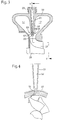
- Fig. 2 is a schematic section of a double flow Exhaust gas turbocharger 13 shown.
- the housing 23 has one the partition 51 separating the flow channels 17.
- a partition channel 52 is provided on the a bypass line 23 can be connected.
- a nozzle 54 arranged at a free end 53 of the partition 51 near the turbine wheel 28.
- the nozzle 54 points directly to the Partition duct 52 adjoining nozzle duct 56, the one has nozzle opening 33 facing turbine wheel 28.
- the Nozzle opening 33 is at a flat exit angle to the Turbine wheel 28 arranged, as shown in Fig. 3.
- the air mass supplied via the bypass line 23 can thus essentially tangentially into the radial ring channel 34 flow in and onto the blades 37 of the turbine wheel 28 to meet.
- the Nozzle ring 57 can be manufactured as a separate component. This allows the manufacturing accuracy of the Nozzle ring 57, very high requirements due of the extremely small nozzle channels 56 and nozzle openings 57 and their strong influences on the system behavior of the turbine 18 are met. Alternatively, it can be provided that the Nozzle channels 56 and nozzle openings 33 in one piece with the Partition 51 are formed.
- the bypass lines 23 have a small cross section, wherein the cross section of the bypass line 23 downstream the partition duct 52 and the nozzle duct 56 to Taper nozzle opening 33 continuously. This can achieved that the flow rates despite the small flow cross sections in the feeds relative low and thus low-loss, due to of the expansion cross section immediately after the nozzle opening 33 close to the turbine wheel due to the heights Pressure ratios supersonic speeds for the Air masses can result even at relatively small Turbine efficiencies result in high turbine performance.
- an annular channel or an annular space is provided instead of one or more partition channels 52 in the partition 51 .
- This can the air mass evenly over the circumference of the partition 51 flow in, at the free end 53 of the partition 51 also a nozzle ring channel with individual nozzles can be provided.
- the nozzle ring 57 with the nozzles 54 distributed over the circumference can alternatively be designed as a guide grill, whereby the Air mass also deflected analogously to the nozzles 54 and below a flat exit angle in the radial ring channel 34 close of the turbine wheel 28 can flow.
- Fig. 2 and Fig. 3 as also the alternative embodiment with a ring channel and the guide screen assigned to the partition 51 can also be used multi-flow turbocharger radial turbines used become.
- both Individual nozzles 54, a nozzle ring 57 or a guide vane on one free end 53 of the partition 51 may be provided, both individual partition channels 52 and an annular space exhibit.
- Such an additional supply of Air masses over the partition 51 immediately before that Turbine wheel 28 in the radial ring channel 34 can in particular be used in so-called turbo brake systems, because an increase in temperature can be reduced here.
- a nozzle arrangement described for FIGS. 2 and 3 on free end 53 of a partition 51 can have a high charge enable the internal combustion engine, for example during the braking phase by a more energetically favorable Loss behavior of the gas after the cylinder up to Turbine wheel 28 for the implementation of work within the turbine 18. This is because the compressor 12 requires Air mass directly related to the exploitation of the Internal combustion engine released exergy in the turbine 18 and stands for the amount of achievable braking power. Next Such a modification can be used in braking operation the turbine 18 can also be used as an acceleration aid.
- a high-pressure tract in front of the turbine wheel 28 also to increase the power of the turbine 18 additional water injection, e.g. emergency braking, be used.
- additional water injection e.g. emergency braking
- the Bypass lines 23 to the partition duct 52 from relative large-volume exhaust manifolds can be arranged independently can, so that these are small in cross section Bypass lines 23 for a targeted and metered Transport of any fluids to the turbine 18 or subsequent converters and filters advantageously let insert.
Description
Die Erfindung betrifft eine Motorbremsvorrichtung für eine Brennkraftmaschine gemäß dem Oberbegriff des Anspruchs 1.The invention relates to an engine brake device for a Internal combustion engine according to the preamble of claim 1.
Aus der gattungsbildenden JP-A-4 246237 ist eine Motorbremsvorrichtung für eine Brennkraftmaschine bekannt, die einen Abgasturbolader mit einer Turbine und einem Verdichter sowie eine Abgasleitung und eine Ansaugleitung aufweist. Stromauf der Turbine ist eine Abgasabsperrvorrichtung in der Abgasleitung angeordnet, wobei stromauf der Abgasabsperrvorrichtung eine von der Abgasleitung abführende Bypassleitung vorgesehen ist, die in einem Bereich nahe eines Turbinenrades einmündet. Des weiteren wird eine die Bypassleitung durchströmende Luftmasse über zumindest eine am freien Ende einer Trennwand einer mehrflutigen Turbine angeordneten Düsenöffnung einem Radialringkanal der Turbine zugeführt. In der Trennwand ist zumindest ein Trennwandkanal angeordnet, der jeweils in eine Düsenöffnung mündet. Der Trennwandkanal hat dabei einen zylindrischen Kanalverlauf.From the generic JP-A-4 246237 is one Engine brake device for an internal combustion engine known an exhaust gas turbocharger with a turbine and a compressor and has an exhaust pipe and an intake pipe. An exhaust gas shut-off device is located in the upstream of the turbine Exhaust line arranged, upstream of the Exhaust shut-off device a leading away from the exhaust pipe Bypass line is provided, which is in an area near a Turbine wheel opens. Furthermore, one becomes the Air mass flowing through the bypass line via at least one am free end of a partition of a multi-flow turbine arranged nozzle opening a radial ring channel of the turbine fed. At least one partition duct is in the partition arranged, each opening into a nozzle opening. The The partition duct has a cylindrical duct profile.
Die US 3,009,320 offenbart eine Starteinrichtung für einen Turbinenmotor, bei der eine auf eine Turbinenrad gerichtete Düse einen verjüngenden Kanalverlauf aufweist. US 3,009,320 discloses a starting device for one Turbine engine, one directed at a turbine wheel Nozzle has a tapered channel.
Aus der DE 28 24 598 C2 ist eine Motorbremse für eine mit einem Abgasturbolader versehene Brennkraftmaschine bekannt, bei der in einer Abgasleitung zwischen Motor und Turbine eines Turboladers eine Abgasabsperrvorrichtung vorgesehen ist. Diese ist als Drehventil mit einem schwenkbaren Ventilkörper ausgebildet, dessen Achse senkrecht zu der Abgasleitung angeordnet ist. Diese Abgasabsperrvorrichtung ist in einer Offenstellung anordenbar, bei der die Abgase ungehindert zur Turbine des Turboladers gelangen. In einer Schließstellung des Drehventils kann noch ein Reststrom des Abgases zur Turbine des Turboladers gelangen, durch den ein Turbinenrad der Turbine angetrieben wird.From DE 28 24 598 C2 there is a motor brake for one an internal combustion engine provided with an exhaust gas turbocharger, in the exhaust pipe between the engine and turbine an exhaust gas shut-off device is provided for a turbocharger is. This is a rotary valve with a swivel Valve body formed, the axis of which is perpendicular to the Exhaust pipe is arranged. This exhaust valve can be arranged in an open position in which the exhaust gases reach the turbine of the turbocharger unhindered. In a Closed position of the rotary valve can still be a residual current Exhaust gas get to the turbine of the turbocharger through which a Turbine wheel of the turbine is driven.
Desweiteren ist aus der US-PS 3,591,959 eine Motorbremsvorrichtung für eine Brennkraftmaschine bekannt, bei der zwischen einem Motor und einem Abgasturbolader eine Abgasabsperrvorrichtung vorgesehen ist, mit der ein vorderes und hinteres Auslaß-Sammelrohr einer 6-Zylinder-Brennkraftmaschine absperrbar ist.Furthermore, an engine brake device is known from US Pat. No. 3,591,959 known for an internal combustion engine in which between an engine and an exhaust gas turbocharger Exhaust shut-off device is provided with which a front and rear exhaust manifold of a 6-cylinder internal combustion engine is lockable.
Beide Motorbremsvorrichtungen mit einer vor dem Abgasturbolader angeordneten Abgasabsperrvorrichtung weisen den Nachteil auf, daß im Bremsbetrieb bei geschlossener Abgasabsperrvorrichtung die Turbinenleistung im wesentlichen auf Null reduziert wird. Dadurch wird ebenfalls die Turbolader-Drehzahl verringert, wodurch eine Aufladung der Brennkraftmaschine nahezu ausbleibt. Die an den Luftmassenstrom zu übertragende Bremsenergie wird durch die verringerte Luftmenge stark eingeschränkt. Eine hohe geforderte Bremsleistung geht dabei mit einer hohen Motoraustrittstemperatur der Luft einher, wodurch der Motor unter einer hohen Temperaturbelastung steht. Im Bremsbetrieb erfolgt bei einer derartigen Anordnung desweiteren bei hoher Bremsleistungsforderung ein hoher Auspuff-Sammelleitungsdruck-Bedarf, wodurch das Problem des Ventil-Schwimmens auftritt. Der Auspuff-Sammelleitungsdruck kann die Kraft von Auslaßventilfedern überschreiten, wodurch die Motorbremswirkung weiter verschlechtert wird.Both engine braking devices with one in front of the exhaust gas turbocharger arranged exhaust shut-off device have the Disadvantage that in the braking mode when closed Exhaust shutdown essentially affects turbine performance is reduced to zero. This also makes the Turbocharger speed is reduced, thereby charging the Internal combustion engine is almost absent. The Andes Air mass flow braking energy is transmitted by the greatly reduced amount of air. A high required braking power goes with a high Engine outlet temperature is accompanied by air, causing the engine is under a high temperature load. In braking mode with such an arrangement, furthermore, takes place at high Braking power requirement a high exhaust manifold pressure requirement, which eliminates the problem of valve floating occurs. The exhaust manifold pressure can be the force of Exhaust valve springs exceed, causing the engine braking effect is deteriorated further.
Der Erfindung liegt deshalb die Aufgabe zugrunde, eine Motorbremsvorrichtung für eine Brennkraftmaschine mit einem Abgasturbolader zu schaffen, bei der die Bremsleistung bei geringerer Temperaturbelastung von Motor und Abgasleitung erhöht wird.The invention is therefore based on the object Engine brake device for an internal combustion engine with a Exhaust gas turbocharger to create, in which the braking power lower temperature load on the engine and exhaust pipe is increased.
Diese Aufgabe wird erfindungsgemäß durch die kennzeichnenden Merkmale des Anspruchs 1 gelöst.This object is achieved by the characterizing Features of claim 1 solved.
Eine vor einer Abgasabsperrvorrichtung angeordnete und abzweigende Bypassleitung, die in einem Bereich nahe eines Turbinenrades einmündet, weist den Vorteil auf, daß die dem Turbinenrad zugeführte Luftmassen unter hoher Strömungsgeschwindigkeit zugeführt werden, wodurch die Turboladerdrehzahl im Vergleich zu der geschlossenen Abgasabsperrvorrichtung aus dem Stand der Technik nicht gegen Null geht. Dadurch wird die auf der Saugseite der Brennkraftmaschine zugeführte Luftmasse, die deutlich über dem Umgebungsdruck liegt, in die Motorzylinder gepreßt, wodurch insgesamt ein höherer Luftmassendurchsatz in der Brennkraftmaschine erzielt werden kann. Dadurch kann gegenüber der aus dem Stand der Technik bekannten Abgasabsperrvorrichtung eine zumindest gleich große Bremsleistung bei einer geringeren Temperaturbelastung in der Brennkraftmaschine und der Abgasleitung erzielt werden. Diese Anordnung hat in Versuchen gezeigt, daß dadurch sogar eine deutliche Erhöhung der Bremsleistung durch die verdichtete Luft, die der Brennkraftmaschine zugeführt wird, realisiert werden kann. A arranged in front of an exhaust gas shut-off device branching bypass line in an area near a Turbine wheel opens, has the advantage that the Air masses fed to turbine wheel under high flow velocity are supplied, causing the turbocharger speed compared to the closed exhaust shut-off device does not approach zero from the prior art. This is the on the suction side of the engine supplied air mass that is well above the ambient pressure lies, pressed into the engine cylinder, making a total achieved higher air mass flow rate in the internal combustion engine can be. This can be compared to that of the prior art Known exhaust gas shutoff device at least one The same braking power with a lower temperature load in the internal combustion engine and the exhaust pipe be achieved. This arrangement has shown in experiments that thereby even a significant increase in braking performance the compressed air that is fed to the internal combustion engine will be realized.
Nach einer vorteilhaften Ausgestaltung der Erfindung ist vorgesehen, daß die Bypassleitung die Luftmassen über zumindest eine am Ende einer Trennwand eines Turbinengehäuses angeordneten Düsenöffnung einem Radialringkanal der Turbine zuführt. Diese Anordnung betrifft mehrflutige, insbesondere zweiflutige, Radialturbinen. Dadurch können die Luftmassen dicht vor dem Turbinenrad zugeführt und ein hoher Turbinenradwirkungsgrad erzielt werden.According to an advantageous embodiment of the invention it is provided that the bypass line over the air masses at least one at the end of a partition of a turbine housing arranged nozzle opening a radial ring channel of the turbine feeds. This arrangement concerns multi-flow, in particular double-flow, radial turbines. This allows the air masses fed close to the turbine wheel and a high one Turbine wheel efficiency can be achieved.
Nach einer weiteren vorteilhaften Ausgestaltung der Erfindung ist vorgesehen, daß in einer Trennwand einer mehrflutigen Radialturbine Trennwandkanäle vorgesehen sind, die jeweils mit einer Düsenöffnung in Verbindung stehen. Alternativ kann vorgesehen sein, daß in der Trennwand ein Ringraum vorgesehen ist, der sich bis zu den Düsenöffnungen erstreckt. Diese beiden Alternativen weisen eine einfache und kostengünstige Ausgestaltung von Kanälen auf, um die Luftmasse einem Ringkanal vor dem Turbinenrad zuzuführen.According to a further advantageous embodiment of the invention it is provided that in a partition a multi-flow Radial turbine partition channels are provided, each communicate with a nozzle opening. Alternatively, you can be provided that an annular space is provided in the partition which extends to the nozzle openings. This Both alternatives are simple and inexpensive Design channels on to the air mass one Feed ring channel in front of the turbine wheel.
Nach einer weiteren vorteilhaften Ausgestaltung der Erfindung ist vorgesehen, daß sich der bzw. die Trennwandkanäle und der bzw. die Ringräume zum freien Ende der Trennwand verjüngen und die sich daran anschließenden Düsenkanäle an ihren Düsenöffnungen den engsten Querschnitt aufweisen. Dadurch kann bewirkt werden, daß insbesondere durch eine tangentiale Austrittsrichtung zu dem Turbinenrad eine hohe drallförmige Turbinenradzuströmung erzielt werden kann. Die Zuführung der Luftmasse erfolgt vorteilhafterweise über dünne Rohrleitungen. Die Luftmassen stehen unter hohem Druck und können durch die Düsenöffnungen vor dem Turbinenrad mit einer hohen Strömungsgeschwindigkeit austreten. Die Drücke, die beispielsweise über 50 bar liegen können, bewirken, daß die Strömungsgeschwindigkeiten trotz der kleinen Strömungsquerschnitte in den Zuführungen relativ gering und damit verlustarm sind. Im Expansionsquerschnitt nahe vor dem Turbinenrad ergeben sich dann durch die hohen Druckverhältnisse Überschallgeschwindigkeiten der Luftmassen und damit auch bei relativ kleinen Turbinenwirkungsgrade hohe Turbinenleistungen. Die Turbine kann in dieser Betriebsweise als reine Impulsturbine analog der Pelton-Gleichdruckturbine arbeiten. Alternativ kann vorgesehen sein, daß bei getrennten Einzeldüsen bzw. Zuführung der Luftmassen über bestimmte Düsenöffnungen eine hohe Teilbeaufschlagung ermöglicht ist. Dies kann durch die Zündfolge des Motors bzw. dem Öffnen der Steuerventile im Zylinder für die einzelnen Düsenöffnungen erfolgen und somit eine phasenmäßige Nutzung der Zuführung der Luftmassen durch die einzelnen Düsenöffnungen bestimmt werden.According to a further advantageous embodiment of the invention it is provided that the or the partition channels and or taper the annular spaces to the free end of the partition and the adjoining nozzle channels on their Nozzle openings have the narrowest cross-section. Thereby can be caused in particular by a tangential Direction of exit to the turbine wheel a high swirl Turbine wheel inflow can be achieved. The feeding of the Air mass is advantageously carried out via thin Pipelines. The air masses are under high pressure and can through the nozzle openings in front of the turbine wheel with a emerge at high flow rates. The pressures that for example, can be above 50 bar, cause the Flow velocities despite the small Flow cross sections in the feed lines are relatively small and so are low loss. In the expansion cross section close to the Turbine wheel then result from the high Pressure ratios Supersonic velocities of the air masses and thus high even with relatively small turbine efficiencies Turbine performance. The turbine can operate in this mode as a pure impulse turbine analogous to the Pelton constant pressure turbine work. Alternatively, it can be provided that with separate Individual nozzles or supply of air masses via certain A high partial loading is made possible for the nozzle openings. This can be done by firing the engine or opening the engine Control valves in the cylinder for the individual nozzle openings take place and thus a phased use of the feeder the air masses determined through the individual nozzle openings become.
Eine derartige Zuordnung der Luftzuführung kann an den jeweiligen Zylindern durch die wirkungsgradgünstigste zeitliche Schaltung bestimmt sein. Dabei können die über den Umfang angeordneten Düsenöffnungen mit Luftmassen hintereinander von den Druckstößen durchlaufen werden oder eine gemischte Beaufschlagung einzelner Düsenöffnungen erfolgen.Such an assignment of the air supply can to the respective cylinders by the most efficient timing should be determined. You can use the Circumferentially arranged nozzle openings with air masses are successively run through by the pressure surges or a mixed application of individual nozzle openings respectively.
Nach einer weiteren vorteilhaften Ausgestaltung der Erfindung ist vorgesehen, daß der Düsenkanal und die Düsenöffnung in einem relativ zur Umfangsrichtung des Turbinenrades flachen Austrittswinkel angeordnet ist. Dadurch kann erzielt werden, daß bei gleichzeitiger Beaufschlagung der beiden Strömungskanäle und der Düsen in der Trennwand die Strömungswinkel nahezu identisch sein können, da die über die Strömungskanäle zugeführte Luftmassen aufgrund der hohen Strömungsgeschwindigkeiten mit beschleunigt werden, die beim Auftreten der Luftmassen aus den Düsenöffnungen erfolgen. Somit kann eine hohe Turbinenleistung durch die große Drallkomponente der Strömung gegeben sein.According to a further advantageous embodiment of the invention it is provided that the nozzle channel and the nozzle opening in a flat relative to the circumferential direction of the turbine wheel Exit angle is arranged. This can be achieved that with simultaneous action on the two Flow channels and the nozzles in the partition Flow angles can be almost identical because of the over the Air masses supplied to flow channels due to the high Flow velocities are accelerated with the Air masses occur from the nozzle openings. Thus a high turbine output can be achieved by the large Swirl component of the flow can be given.
Nach einer weiteren vorteilhaften Ausgestaltung der Erfindung ist vorgesehen, daß mehrere Düsenöffnungen im Gehäuse des Turbinenrades vorgesehen sind, so daß eine über den Umfang verteilte gleichmäßige Zuführung und Beaufschlagung mit Luftmassen gegeben ist. Dadurch können gleichmäßige Kräfte auf das Turbinenrad wirken, wodurch wiederum eine geringe Lagerbelastung auf die die Welle zwischen Verdichterrad und Turbinenrad aufnehmenden Lager wirken kann.According to a further advantageous embodiment of the invention it is envisaged that several nozzle openings in the housing of the Turbine wheel are provided so that one over the circumference distributed even supply and loading with Air mass is given. This allows even forces act on the turbine wheel, which in turn causes a small Bearing load on the shaft between the compressor wheel and Turbine wheel receiving bearings can act.
Nach einer weiteren vorteilhaften Ausgestaltung der Erfindung ist vorgesehen, daß die Düsenöffnungen im wesentlichen tangential zum Turbinenrad angeordnet sind. Dadurch wird die drallförmige Einströmung erzielt. Dadurch wird die Turbinenleistung gesteigert und ein höherer Luftmassenstrom ermöglicht.According to a further advantageous embodiment of the invention it is intended that the nozzle openings essentially are arranged tangentially to the turbine wheel. This will make the swirl-shaped inflow achieved. This will make the Turbine output increased and a higher air mass flow enables.
Nach einer weiteren vorteilhaften Ausgestaltung der Erfindung ist vorgesehen, daß die Abgasabsperrvorrichtung und zumindest der Abzweig der Bypassleitung in dem Turbinengehäuse integriert sind. Dadurch kann eine Bauteileminimierung gegeben sein. Zudem führt dies zu einer schnelleren Montage, da eine Montage der Abgasabsperrvorrichtung und das Anbringen eines Abzweigs in der Abgasleitung ausbleiben kann.According to a further advantageous embodiment of the invention it is provided that the exhaust gas shut-off device and at least the branch of the bypass line in the turbine housing are integrated. This can minimize components be given. This also leads to faster assembly, there assembly and installation of the exhaust gas shut-off device a branch in the exhaust pipe can fail to appear.
Weitere zweckmäßige Ausgestaltungen der Erfindung sind in den Unteransprüchen und in der nachfolgenden Beschreibung angegeben.Further expedient embodiments of the invention are in the Subclaims and in the description below specified.
Anhand von in der Zeichnung dargestellten bevorzugten Ausführungsbeispielen wird die Erfindung nachfolgend näher erläutert. Es zeigen:
- Fig. 1
- eine schematische Darstellung der erfindungsgemäßen Anordnung einer Bremsvorrichtung,
- Fig. 2
- eine Ausführungsform einer zweiflutigen Radialturbine und
- Fig. 3
- eine schematische Seitenansicht entlang der Linie V-V in Fig. 2.
- Fig. 1
- 1 shows a schematic representation of the arrangement of a braking device according to the invention,
- Fig. 2
- an embodiment of a double-flow radial turbine and
- Fig. 3
- 2 shows a schematic side view along the line VV in FIG. 2.
In Fig. 1 ist ein Motor 10 einer mehrzylindrischen
Brennkraftmaschine dargestellt. Eine erste Ansaugleitung 11
führt Luftmassen einem Verdichter 12 eines Abgasturboladers
13 zu. Die Luftmasse wird komprimiert und über eine zweite
Druckleitung 14 des Verdichters dem Brennraum des Motors 10
zugeführt. Auf einer Abgasseite des Motors 10 ist eine erste
Abgasleitung 16 vorgesehen, die in einen Strömungskanal 17
einer Turbine 18 des Abgasturboladers 13 führt. Über eine
zweite Abgasleitung 19 stromab der Turbine 18 wird das Abgas
über eine Abgasreinigungsanlage (nicht dargestellt) ins Freie
geführt.In Fig. 1, an
Auf der Abgasseite des Motors 10 ist eine Motorbremsvorrichtung
21 vorgesehen, die eine Abgasabsperrvorrichtung
22 und eine stromauf der Abgasabsperrvorrichtung 22
abzweigende Bypassleitung 23 aufweist. Parallel zu der
Abgasabsperrvorrichtung 22 ist eine Abblasevorrichtung 24
angeordnet, die mit einer ersten Verbindungsleitung 26
gekoppelt ist. Mit der Signalleitung 25 wird die
Abblaseeinrichtung geregelt. Je nach geforderter
Bremsleistung kann das Abblaseventil, das eine genaue
Dosierung der Luftmenge ermöglicht, geöffnet werden. Der
Abblasevorrichtung kommt auch die Aufgabe der
Überlastungssicherung zu. Ab einem vorgegebenen maximalen
Druck hinter den Auslaßventilen wird das Abblaseventil zur
Öffnung angesteuert. Die Leitung 27a stromab des
Abblaseventils 24 mündet in der Leitung 19. Möglich wäre auch
alternativ eine Leitung 27b, die in der Turbinenspirale 17
endet.On the exhaust side of the
Die Abgasabsperrvorrichtung 22 ist als Bremsklappe,
vorzugsweise als Schmetterlingsklappe, ausgebildet. Die
Bremsklappe 22 entspricht dem Querschnitt der Abgasleitung
16, so daß diese die Abgasleitung 16 im Schiebe- bzw.
Bremsbetrieb vollständig schließt. Dadurch baut sich vor
dieser Bremsklappe 22 ein Abgasdruck auf. Die aufgestauten
Luftmassen strömen dadurch in die Bypassleitung 23, die nahe
des Turbinenrades 28 in den Strömungskanal 17 einmündet.
Somit kann die Turbinendrehzahl hoch gehalten werden, wodurch
das zwangsweise über eine Welle 29 verbundene Verdichterrad
31 die angesaugte Luft komprimiert und dem Motor 10 zuführt.
Dadurch ist in diesem System ein erhöhter Luftmassendurchsatz
gegeben, wodurch die Temperatur der Luft hinter dem Motor
nieder gehalten werden kann.The exhaust gas shut-off
Die mit der Abgasabsperrvorrichtung 22 in Verbindung stehende
Abblasevorrichtung 24 ist als Dosier- und Überdruckventil
ausgebildet. Dadurch ist der maximale Staudruck vor der
Abgasabsperreinrichtung 22 begrenzbar. Diese Druckbegrenzung
weist den Vorteil auf, daß eine Überwachung von ggf. überhöht
aufgetretenen Drücken gegeben ist. Zusätzlich bietet dieses
Überdruckventil eine Auslegungsmöglichkeit für eine Anhebung
des Ladedrucks bei niederen Motordrehzahlen. Mit Hilfe einer
intelligenten Regelung des Abblaseventils läßt sich die
Bremscharakteristik des Motors vorteilhaft beeinflussen.The one connected to the exhaust
Sobald ein zu hoher Staudruck an der Abgasabsperrvorrichtung
22 anliegt, öffnet sich das Überdruckventil, so daß die
aufgestauten Luftmassen über die erste und zweite
Verbindungsleitung 26, 27a oder 27b in die zweite
Abgasleitung 19 bzw. Turbinenspirale 17 abströmen können.As soon as too high back pressure on the exhaust gas shut-off
Die Bypassleitung 23 weist einen nicht dargestellten
Verteiler auf, der alle in dem Gehäuse 32 angeordneten
Düsenöffnungen 33 versorgt. Alternativ kann vorgesehen sein,
daß anstelle der Düsenöffnungen 33 ein Leitgitter in dem
Gehäuse 32 vorgesehen ist. Durch die tangentiale Anordnung
der Düsenöffnungen 33, die beispielsweise 10° gegenüber der
Eintrittsfläche 36 angeordnet sein können, werden die
Luftmassen drallförmig zugeführt. Dadurch kann eine hohe
Turbinenleistung bzw. Turbinendrehzahl erreicht werden, die
wiederum einen hohen Luftdurchsatz des Motors 10 bewirkt. The
Die Düsenöffnungen 33 stellen praktisch den Bremsspalt dar,
der dem aus dem Stand der Technik bekannten Bremsklappenspalt
mit einer definierten Größe für zugelassene Motorgegendrücke
im wesentlichen entspricht. Die Summe der Düsenöffnungsquerschnitte
ist in der Größenordnung ausgebildet wie ein
Bremsklappenspalt der Abgasabsperrvorrichtung 22, der aus dem
Stand der Technik bekannt ist. The nozzle openings 33 practically represent the brake gap,
the brake flap gap known from the prior art
with a defined size for approved engine back pressures
essentially corresponds. The sum of the nozzle opening cross sections
is of the order of magnitude of a
Airbrake gap of the exhaust shut-off
In Fig. 2 ist ein schematischer Schnitt eines zweiflutigen
Abgasturboladers 13 dargestellt. Das Gehäuse 23 weist eine
die Strömungskanäle 17 trennende Trennwand 51 auf. In dieser
Trennwand 51 ist ein Trennwandkanal 52 vorgesehen, an den
eine Bypassleitung 23 anschließbar ist. An einem freien Ende
53 der Trennwand 51 nahe dem Turbinenrad 28 ist eine Düse 54
angeordnet. Die Düse 54 weist einen unmittelbar sich an den
Trennwandkanal 52 anschließenden Düsenkanal 56 auf, der eine
zum Turbinenrad 28 weisende Düsenöffnung 33 aufweist. Die
Düsenöffnung 33 ist unter einem flachen Austrittswinkel zum
Turbinenrad 28 angeordnet, wie in Fig. 3 dargestellt ist.
Somit kann die über die Bypassleitung 23 zugeführte Luftmasse
im wesentlichen tangential in den Radialringkanal 34
einströmen und auf die Schaufeln 37 des Turbinenrades 28
treffen. In Fig. 2 is a schematic section of a double flow
Im Ausführungsbeispiel gemäß Fig. 2 und Fig. 3 sind mehrere
über den Umfang des Gehäuses 32 verteilt angeordnete
Trennwandkanäle 52 vorgesehen, die am freien Ende 53 der
Trennwand 51 in einen Düsenring 57 münden, der entsprechend
der Anzahl der Trennwandkanäle 52 Düsen 54 aufweist. Der
Düsenring 57 kann als separates Bauteil gefertigt sein.
Dadurch können die an die Fertigungsgenauigkeit des
Düsenringes 57 gestellten, sehr hohen Anforderungen aufgrund
der extrem kleinen Düsenkanäle 56 und Düsenöffnungen 57 und
deren starken Einflüsse auf das Systemverhalten der Turbine
18 erfüllt werden. Alternativ kann vorgesehen sein, daß die
Düsenkanäle 56 und Düsenöffnungen 33 einstückig mit der
Trennwand 51 ausgebildet sind.In the exemplary embodiment according to FIGS. 2 and 3, there are several
distributed over the circumference of the
Die Bypassleitungen 23 weisen einen geringen Querschnitt auf,
wobei sich der Querschnitt der Bypassleitung 23 stromab über
den Trennwandkanal 52 und den Düsenkanal 56 bis zur
Düsenöffnung 33 kontinuierlich verjüngen. Dadurch kann
erzielt werden, daß die Strömungsgeschwindigkeiten trotz der
kleinen Strömungsquerschnitte in den Zuführungen relativ
gering und damit verlustarm ausgebildet sind, wobei aufgrund
des Expansionsquerschnittes unmittelbar nach der Düsenöffnung
33 nahe dem Turbinenrad sich aufgrund der höhen
Druckverhältnisse Überschallgeschwindigkeiten für die
Luftmassen ergeben können, die auch bei relativ kleinen
Turbinenwirkungsgraden eine hohe Turbinenleistung bewirken. The bypass lines 23 have a small cross section,
wherein the cross section of the
Desweiteren kann alternativ vorgesehen sein, daß anstelle von
einem oder mehreren Trennwandkanälen 52 in der Trennwand 51
ein Ringkanal bzw. ein Ringraum vorgesehen ist. Dadurch kann
gleichmäßig über den Umfang der Trennwand 51 die Luftmasse
zuströmen, wobei am freien Ende 53 der Trennwand 51 ebenfalls
ein Düsenringkanal mit Einzeldüsen vorgesehen sein kann.Furthermore, it can alternatively be provided that instead of
one or
Der Düsenring 57 mit den über den Umfang verteilten Düsen 54
kann alternativ als Leitgitter ausgebildet sein, wodurch die
Luftmasse ebenfalls analog der Düsen 54 umgelenkt und unter
einem flachen Austrittswinkel in den Radialringkanal 34 nahe
des Turbinenrades 28 einströmen kann.The
Die in Fig. 2 und Fig. 3 dargestellten Ausführungsformen als
auch die alternative Ausführungsform mit einem Ringkanal und
dem der Trennwand 51 zugeordneten Leitgitter kann ebenso bei
mehrflutigen Abgasturbolader-Radialturbinen eingesetzt
werden. Ebenso kann entsprechend dem Einsatzfall sowohl
Einzeldüsen 54, ein Düsenring 57 oder ein Leitgitter an einem
freien Ende 53 der Trennwand 51 vorgesehen sein, die sowohl
einzelne Trennwandkanäle 52 als auch einen Ringraum
aufweisen. Eine derartige zusätzliche Zuführung der
Luftmassen über die Trennwand 51 unmittelbar vor das
Turbinenrad 28 in den Radialringkanal 34 kann insbesondere
bei sogenannten Turbo-Brake-Systemen eingesetzt werden, da
hier eine Temperaturerhöhung abgesenkt werden kann.The embodiments shown in Fig. 2 and Fig. 3 as
also the alternative embodiment with a ring channel and
the guide screen assigned to the
Eine zu Fig. 2 und Fig. 3 beschriebene Düsenanordnung am
freien Ende 53 einer Trennwand 51 kann eine hohe Aufladung
der Brennkraftmaschine ermöglichen, die beispielsweise
während der Bremsphase durch ein energetisch günstigeres
Verlustverhalten des Gases nach dem Zylinder bis zum
Turbinenrad 28 für die Arbeitsumsetzung innerhalb der Turbine
18. Dies beruht darauf, daß die vom Verdichter 12 geforderte
Luftmasse im direkten Zusammenhang zur Ausnutzung der von der
Brennkraftmaschine abgegebenen Exergie in der Turbine 18 und
damit zur Höhe der erreichbaren Bremsleistung steht. Neben
dem Einsatz im Bremsbetrieb kann eine derartige Modifikation
der Turbine 18 auch als Beschleunigungshilfe genutzt werden.A nozzle arrangement described for FIGS. 2 and 3 on
Desweiteren kann ein Hochdrucktrakt vor dem Turbinenrad 28
auch zur Leistungserhöhung der Turbine 18 mittels
zusätzlicher Wassereinspritzung, z.B. bei Notbremsungen,
eingesetzt werden. Desweiteren kann vorgesehen sein, daß die
Bypassleitungen 23 zum Trennwandkanal 52 von relativ
großvolumigen Austrittskrümmern unabhängig angeordnet sein
können, so daß sich diese im Querschnitt kleinen
Bypassleitungen 23 für einen gezielten und dosierten
Transport von beliebigen Fluiden zur Turbine 18 bzw.
nachfolgenden Konvertern und Filtern vorteilhafterweise
einsetzen lassen.Furthermore, a high-pressure tract in front of the
Claims (12)
- Motor brake device, for an internal-combustion engine, which has an exhaust-driven supercharger (13) with a turbine (18) and a compressor (12), and also an exhaust pipe (16, 19) and a suction pipe (11, 14), and with at least one exhaust shutoff device (32) disposed upflow of the turbine, in the exhaust pipe (16), whereby at least one by-pass pipe (23), which opens in an area near to a turbine wheel, and leads off from the exhaust pipe (16, 19), is provided upflow from the exhaust shutoff device (22), and whereby an air mass which flows through the by-pass pipe (23) is supplied to a radial, annular duct (34) of the turbine (18), via at least one jet orifice (39) disposed at the free end (53) of a partition of a multi-flow turbine (18), and whereby at least one partition duct (32), which opens, in each case, into the jet orifice (33), is disposed in the partition (51), characterized in that the at least one duct (52) going to the jet orifice (33) is developed such that it narrows, and the jet orifice (33) has the narrowest cross-section, whereby, at the free end (53) of the partition (51), a nozzle ring (57) with at least one nozzle duct (56) and jet orifice (33), forming a nozzle (54), are provided, and the nozzle duct (56) going to the jet orifice (33) is developed such that it narrows, or in that a guide grid is disposed at the free end (53) of the partition (51).
- Motor brake device in accordance with claim 1, characterized in that an annular space, which extends as far as the at least one jet orifice (33), is provided at the partition (51).
- Motor brake device in accordance with claim 1 or 2, characterized in that a nozzle (54) is disposed on each associated partition duct (52) in the partition (51).
- Motor brake device in accordance with any one of claims 1 to 3, characterized in that the jet orifice (33) of the partition (51) has a level outlet angle, relative to the peripheral direction of the turbine wheel (28).
- Motor brake device in accordance with any one of claims 1 to 4, characterized in that the total cross-sectional area of the jet orifice (33) corresponds to at least a specific size of a brake valve gap for an approved engine back pressure of an exhaust shutoff valve (22).
- Motor brake device in accordance with any one of the preceding claims, characterized in that at least the exhaust shutoff device (22) and the at least one branch for the bypass pipe (23), disposed upflow of the exhaust shutoff device (22), are disposed in the casing (32) of the turbine (28).
- Motor brake device in accordance with any one of the preceding claims, characterized in that at least the exhaust shutoff device (22) is connected to the outward-blower device (24), the connection pipe (27a or 27b) of which, disposed downflow of it, opens into the exhaust pipe (19) or turbine spirals (17).
- Motor brake device in accordance with claim 7, characterized in that the outward-blower device (24) is developed as an excess-pressure valve and can be set to a maximum pressure head in front of the exhaust shutoff device (22).
- Motor brake device in accordance with claim 7 or 8, characterized in that the outward-blower valve (24) is controlled by means of a regulating device (25).
- Motor brake device in accordance with any one of claims 7 to 9, characterized in that the outward-blower device (24) can be controlled in accordance with engine-performance characteristics.
- Motor brake device in accordance with any one of claims 7 to 10, characterized in that, with a fully closed exhaust shutoff device (22), the braking characteristics of the engine (10) can be varied by electronic adjustment of a valve setting of an outward-blower device (24).
- Motor brake device in accordance with any one of the preceding claims, characterized in that, with the exhaust shut-off device in a closed position, the exhaust pipe (16) can be substantially completely shut off.
Applications Claiming Priority (2)
| Application Number | Priority Date | Filing Date | Title |
|---|---|---|---|
| DE19630224 | 1996-07-26 | ||
| DE19630224A DE19630224A1 (en) | 1996-07-26 | 1996-07-26 | Engine brake device |
Publications (2)
| Publication Number | Publication Date |
|---|---|
| EP0821147A1 EP0821147A1 (en) | 1998-01-28 |
| EP0821147B1 true EP0821147B1 (en) | 2000-05-10 |
Family
ID=7800947
Family Applications (1)
| Application Number | Title | Priority Date | Filing Date |
|---|---|---|---|
| EP97109811A Expired - Lifetime EP0821147B1 (en) | 1996-07-26 | 1997-06-17 | Engine braking device for a turbocharged internal combustion engine |
Country Status (3)
| Country | Link |
|---|---|
| US (1) | US6101812A (en) |
| EP (1) | EP0821147B1 (en) |
| DE (2) | DE19630224A1 (en) |
Cited By (1)
| Publication number | Priority date | Publication date | Assignee | Title |
|---|---|---|---|---|
| AT502997B1 (en) * | 2005-12-20 | 2013-09-15 | Man Truck & Bus Oesterreich Ag | DEVICE FOR INCREASING THE BRAKING PERFORMANCE OF A MULTI-CYLINDER INTERNAL COMBUSTION ENGINE OF A VEHICLE DURING ENGINE BRAKE OPERATION |
Families Citing this family (12)
| Publication number | Priority date | Publication date | Assignee | Title |
|---|---|---|---|---|
| US20090205329A1 (en) * | 2002-04-01 | 2009-08-20 | Niket Patwardhan | Heat engine matched to cheap heat source or sink |
| US7150151B2 (en) * | 2002-11-19 | 2006-12-19 | Cummins Inc. | Method of controlling the exhaust gas temperature for after-treatment systems on a diesel engine using a variable geometry turbine |
| DE10260779A1 (en) * | 2002-12-23 | 2004-07-01 | Daimlerchrysler Ag | Exhaust gas turbocharger for an internal combustion engine has a blower in an intake section and an exhaust gas turbine in an exhaust gas branch |
| US7644585B2 (en) * | 2004-08-31 | 2010-01-12 | The United States Of America As Represented By The Administrator Of The U.S. Environmental Protection Agency | Multi-stage turbocharging system with efficient bypass |
| EP1762716B1 (en) * | 2005-09-07 | 2012-11-21 | BorgWarner, Inc. | Exhaust brake with bypass channel |
| RU2544640C2 (en) * | 2009-02-19 | 2015-03-20 | Вольво Ластвагнар Аб | Turbine efficiency control procedure and device |
| AT510236B1 (en) * | 2010-07-26 | 2015-12-15 | MAN Truck & Bus Österreich AG | METHOD FOR MOTOR BRAKING |
| AT510237B1 (en) | 2010-07-26 | 2015-12-15 | MAN Truck & Bus Österreich AG | METHOD FOR MOTOR BRAKING |
| DE102010053057A1 (en) * | 2010-12-01 | 2012-06-06 | Daimler Ag | Charging device for an internal combustion engine |
| DE102012100339A1 (en) * | 2012-01-16 | 2013-07-18 | Universität der Bundeswehr München | Method and device for stabilizing a compressor flow |
| AT512567B1 (en) * | 2012-03-01 | 2014-03-15 | Man Truck & Bus Oesterreich Ag | Function module with an exhaust gas turbocharger and an exhaust manifold |
| CN106438058A (en) * | 2016-12-07 | 2017-02-22 | 东风商用车有限公司 | Engine exhaust pipe with exhaust braking butterfly valve |
Citations (1)
| Publication number | Priority date | Publication date | Assignee | Title |
|---|---|---|---|---|
| US3009320A (en) * | 1959-06-15 | 1961-11-21 | Gen Electric | Fluid impingement starter for turbine engines |
Family Cites Families (8)
| Publication number | Priority date | Publication date | Assignee | Title |
|---|---|---|---|---|
| AT279275B (en) * | 1968-08-07 | 1970-02-25 | Maschf Augsburg Nuernberg Ag | Exhaust throttle for exhaust brakes on supercharged combustion engines |
| US4138849A (en) * | 1977-06-06 | 1979-02-13 | Cummins Engine Company, Inc. | Exhaust braking valve |
| DE3504465C1 (en) * | 1985-02-09 | 1986-01-02 | M.A.N.-B & W Diesel GmbH, 8900 Augsburg | Device for charging an internal combustion engine |
| DE3610131A1 (en) * | 1986-03-26 | 1987-09-17 | Bayerische Motoren Werke Ag | Internal combustion engine, especially diesel engine, as drive unit for vehicles |
| DE3943705C2 (en) * | 1989-10-24 | 1995-07-13 | Daimler Benz Ag | Method for operating an engine brake for an internal combustion engine |
| JP2959143B2 (en) * | 1991-01-31 | 1999-10-06 | いすゞ自動車株式会社 | Turbocharger with generator / motor |
| JPH06278595A (en) * | 1993-03-29 | 1994-10-04 | Jidosha Kiki Co Ltd | Exhaust brake valve device |
| DE19540060A1 (en) * | 1995-10-27 | 1997-04-30 | Daimler Benz Ag | Engine brake device |
-
1996
- 1996-07-26 DE DE19630224A patent/DE19630224A1/en not_active Withdrawn
-
1997
- 1997-06-17 DE DE59701625T patent/DE59701625D1/en not_active Expired - Fee Related
- 1997-06-17 EP EP97109811A patent/EP0821147B1/en not_active Expired - Lifetime
- 1997-07-21 US US08/897,412 patent/US6101812A/en not_active Expired - Fee Related
Patent Citations (1)
| Publication number | Priority date | Publication date | Assignee | Title |
|---|---|---|---|---|
| US3009320A (en) * | 1959-06-15 | 1961-11-21 | Gen Electric | Fluid impingement starter for turbine engines |
Cited By (1)
| Publication number | Priority date | Publication date | Assignee | Title |
|---|---|---|---|---|
| AT502997B1 (en) * | 2005-12-20 | 2013-09-15 | Man Truck & Bus Oesterreich Ag | DEVICE FOR INCREASING THE BRAKING PERFORMANCE OF A MULTI-CYLINDER INTERNAL COMBUSTION ENGINE OF A VEHICLE DURING ENGINE BRAKE OPERATION |
Also Published As
| Publication number | Publication date |
|---|---|
| DE59701625D1 (en) | 2000-06-15 |
| US6101812A (en) | 2000-08-15 |
| DE19630224A1 (en) | 1998-01-29 |
| EP0821147A1 (en) | 1998-01-28 |
Similar Documents
| Publication | Publication Date | Title |
|---|---|---|
| DE19618160C2 (en) | Exhaust gas turbocharger for an internal combustion engine | |
| EP0770772B1 (en) | Engine braking apparatus | |
| EP0531277B1 (en) | Internal combustion engine having an inlet and outlet system, a turbocharger and a pressure accumulator | |
| DE4242494C1 (en) | Adjustable flow-guide for engine exhaust turbocharger - has axially-adjustable annular insert in sectors forming different kinds of guide grilles supplied simultaneously by spiral passages | |
| EP0821147B1 (en) | Engine braking device for a turbocharged internal combustion engine | |
| DE19837978B4 (en) | Air-flow controller in twin stage turbocharged internal combustion engine | |
| WO2007093367A1 (en) | Compressor for an internal combustion engine | |
| WO2010020323A1 (en) | Exhaust gas turbocharger for an internal combustion engine of a motor vehicle | |
| WO2002027164A1 (en) | Exhaust gas turbocharger, supercharged internal combustion engine and corresponding method | |
| WO2010040437A2 (en) | Exhaust gas turbocharger for an internal combustion engine | |
| EP2386761A2 (en) | Compressor housing add-on | |
| WO2009018887A1 (en) | Exhaust gas turbocharger for a reciprocating piston internal combustion engine | |
| DE3034271A1 (en) | TURBINE HOUSING FOR TURBOCHARGER | |
| WO2005001257A1 (en) | Internal combustion engine comprising a compressor in the suction part and method therefor | |
| EP1881173B1 (en) | Diffusor for internal combustion engine and engine with such a diffusor | |
| EP1530671B1 (en) | Exhaust gas turbocharger for an internal combustion engine | |
| EP2058484A1 (en) | Charged combustion engine | |
| EP3244035B1 (en) | Compressor, exhaust gas turbocharger and combustion engine | |
| EP1633967A2 (en) | Internal combustion engine with exhaust gas recycling device and corresponding method | |
| DE102014212606A1 (en) | Motor vehicle and air filter box | |
| DE102011111747A1 (en) | Compressor for exhaust turbocharger of internal combustion engine, particularly gasoline engine of motor vehicle, particularly passenger car, comprises guide element arranged against air flow in axial direction of compressor wheel | |
| DE102018005460B3 (en) | Internal combustion engine for a motor vehicle, in particular for a motor vehicle, method for operating such an internal combustion engine and motor vehicle with such an internal combustion engine | |
| EP0292698B1 (en) | Combustion engine turbocharger | |
| DE2948089A1 (en) | IC engine multistage exhaust gas turbocharger - has concentric by=pass duct round exhaust spiral feed, controlled by valves | |
| DE4038918A1 (en) | Mixer for gaseous media at different pressures - is controlled electronically by transducer which causes mixing member to rotate for direct mixt. of two flows |
Legal Events
| Date | Code | Title | Description |
|---|---|---|---|
| PUAI | Public reference made under article 153(3) epc to a published international application that has entered the european phase |
Free format text: ORIGINAL CODE: 0009012 |
|
| AK | Designated contracting states |
Kind code of ref document: A1 Designated state(s): DE FR GB IT |
|
| 17P | Request for examination filed |
Effective date: 19971217 |
|
| 17Q | First examination report despatched |
Effective date: 19980312 |
|
| RBV | Designated contracting states (corrected) |
Designated state(s): DE FR GB IT |
|
| RAP1 | Party data changed (applicant data changed or rights of an application transferred) |
Owner name: DAIMLERCHRYSLER AG |
|
| GRAG | Despatch of communication of intention to grant |
Free format text: ORIGINAL CODE: EPIDOS AGRA |
|
| GRAG | Despatch of communication of intention to grant |
Free format text: ORIGINAL CODE: EPIDOS AGRA |
|
| GRAH | Despatch of communication of intention to grant a patent |
Free format text: ORIGINAL CODE: EPIDOS IGRA |
|
| GRAH | Despatch of communication of intention to grant a patent |
Free format text: ORIGINAL CODE: EPIDOS IGRA |
|
| GRAA | (expected) grant |
Free format text: ORIGINAL CODE: 0009210 |
|
| ITF | It: translation for a ep patent filed |
Owner name: BARZANO' E ZANARDO ROMA S.P.A. |
|
| AK | Designated contracting states |
Kind code of ref document: B1 Designated state(s): DE FR GB IT |
|
| REF | Corresponds to: |
Ref document number: 59701625 Country of ref document: DE Date of ref document: 20000615 |
|
| ET | Fr: translation filed | ||
| GBT | Gb: translation of ep patent filed (gb section 77(6)(a)/1977) |
Effective date: 20000912 |
|
| PLBE | No opposition filed within time limit |
Free format text: ORIGINAL CODE: 0009261 |
|
| STAA | Information on the status of an ep patent application or granted ep patent |
Free format text: STATUS: NO OPPOSITION FILED WITHIN TIME LIMIT |
|
| 26N | No opposition filed | ||
| REG | Reference to a national code |
Ref country code: GB Ref legal event code: IF02 |
|
| PGFP | Annual fee paid to national office [announced via postgrant information from national office to epo] |
Ref country code: GB Payment date: 20040528 Year of fee payment: 8 |
|
| PGFP | Annual fee paid to national office [announced via postgrant information from national office to epo] |
Ref country code: DE Payment date: 20040604 Year of fee payment: 8 |
|
| PGFP | Annual fee paid to national office [announced via postgrant information from national office to epo] |
Ref country code: FR Payment date: 20040609 Year of fee payment: 8 |
|
| PG25 | Lapsed in a contracting state [announced via postgrant information from national office to epo] |
Ref country code: IT Free format text: LAPSE BECAUSE OF NON-PAYMENT OF DUE FEES Effective date: 20050617 Ref country code: GB Free format text: LAPSE BECAUSE OF NON-PAYMENT OF DUE FEES Effective date: 20050617 |
|
| PG25 | Lapsed in a contracting state [announced via postgrant information from national office to epo] |
Ref country code: DE Free format text: LAPSE BECAUSE OF NON-PAYMENT OF DUE FEES Effective date: 20060103 |
|
| PG25 | Lapsed in a contracting state [announced via postgrant information from national office to epo] |
Ref country code: FR Free format text: LAPSE BECAUSE OF NON-PAYMENT OF DUE FEES Effective date: 20060228 |
|
| GBPC | Gb: european patent ceased through non-payment of renewal fee |
Effective date: 20050617 |
|
| REG | Reference to a national code |
Ref country code: FR Ref legal event code: ST Effective date: 20060228 |