EP0820424B1 - Verfahren zur chemischen dampfinfiltration eines aus kohlenstoff und silicium und/oder bor zusammengesetzten materials - Google Patents
Verfahren zur chemischen dampfinfiltration eines aus kohlenstoff und silicium und/oder bor zusammengesetzten materials Download PDFInfo
- Publication number
- EP0820424B1 EP0820424B1 EP96913580A EP96913580A EP0820424B1 EP 0820424 B1 EP0820424 B1 EP 0820424B1 EP 96913580 A EP96913580 A EP 96913580A EP 96913580 A EP96913580 A EP 96913580A EP 0820424 B1 EP0820424 B1 EP 0820424B1
- Authority
- EP
- European Patent Office
- Prior art keywords
- substrates
- substrate
- gas
- boron
- chamber
- Prior art date
- Legal status (The legal status is an assumption and is not a legal conclusion. Google has not performed a legal analysis and makes no representation as to the accuracy of the status listed.)
- Expired - Lifetime
Links
Images

Classifications
-
- C—CHEMISTRY; METALLURGY
- C23—COATING METALLIC MATERIAL; COATING MATERIAL WITH METALLIC MATERIAL; CHEMICAL SURFACE TREATMENT; DIFFUSION TREATMENT OF METALLIC MATERIAL; COATING BY VACUUM EVAPORATION, BY SPUTTERING, BY ION IMPLANTATION OR BY CHEMICAL VAPOUR DEPOSITION, IN GENERAL; INHIBITING CORROSION OF METALLIC MATERIAL OR INCRUSTATION IN GENERAL
- C23C—COATING METALLIC MATERIAL; COATING MATERIAL WITH METALLIC MATERIAL; SURFACE TREATMENT OF METALLIC MATERIAL BY DIFFUSION INTO THE SURFACE, BY CHEMICAL CONVERSION OR SUBSTITUTION; COATING BY VACUUM EVAPORATION, BY SPUTTERING, BY ION IMPLANTATION OR BY CHEMICAL VAPOUR DEPOSITION, IN GENERAL
- C23C14/00—Coating by vacuum evaporation, by sputtering or by ion implantation of the coating forming material
- C23C14/04—Coating on selected surface areas, e.g. using masks
- C23C14/046—Coating cavities or hollow spaces, e.g. interior of tubes; Infiltration of porous substrates
-
- C—CHEMISTRY; METALLURGY
- C04—CEMENTS; CONCRETE; ARTIFICIAL STONE; CERAMICS; REFRACTORIES
- C04B—LIME, MAGNESIA; SLAG; CEMENTS; COMPOSITIONS THEREOF, e.g. MORTARS, CONCRETE OR LIKE BUILDING MATERIALS; ARTIFICIAL STONE; CERAMICS; REFRACTORIES; TREATMENT OF NATURAL STONE
- C04B35/00—Shaped ceramic products characterised by their composition; Ceramics compositions; Processing powders of inorganic compounds preparatory to the manufacturing of ceramic products
- C04B35/515—Shaped ceramic products characterised by their composition; Ceramics compositions; Processing powders of inorganic compounds preparatory to the manufacturing of ceramic products based on non-oxide ceramics
- C04B35/56—Shaped ceramic products characterised by their composition; Ceramics compositions; Processing powders of inorganic compounds preparatory to the manufacturing of ceramic products based on non-oxide ceramics based on carbides or oxycarbides
- C04B35/565—Shaped ceramic products characterised by their composition; Ceramics compositions; Processing powders of inorganic compounds preparatory to the manufacturing of ceramic products based on non-oxide ceramics based on carbides or oxycarbides based on silicon carbide
- C04B35/571—Shaped ceramic products characterised by their composition; Ceramics compositions; Processing powders of inorganic compounds preparatory to the manufacturing of ceramic products based on non-oxide ceramics based on carbides or oxycarbides based on silicon carbide obtained from Si-containing polymer precursors or organosilicon monomers
-
- C—CHEMISTRY; METALLURGY
- C04—CEMENTS; CONCRETE; ARTIFICIAL STONE; CERAMICS; REFRACTORIES
- C04B—LIME, MAGNESIA; SLAG; CEMENTS; COMPOSITIONS THEREOF, e.g. MORTARS, CONCRETE OR LIKE BUILDING MATERIALS; ARTIFICIAL STONE; CERAMICS; REFRACTORIES; TREATMENT OF NATURAL STONE
- C04B35/00—Shaped ceramic products characterised by their composition; Ceramics compositions; Processing powders of inorganic compounds preparatory to the manufacturing of ceramic products
- C04B35/71—Ceramic products containing macroscopic reinforcing agents
- C04B35/78—Ceramic products containing macroscopic reinforcing agents containing non-metallic materials
- C04B35/80—Fibres, filaments, whiskers, platelets, or the like
Definitions
- the present invention relates to a method of densification of a porous substrate by a material obtained by chemical vapor infiltration and composed of carbon as well as silicon and / or boron.
- a material obtained by chemical vapor infiltration and composed of carbon as well as silicon and / or boron.
- Such material can be silicon carbide, boron carbide, as well as any ternary system intermediate Si-B-C.
- a particular field of application of the invention is the manufacture of parts made of composite material by densification of a fibrous substrate, or preform, by a matrix obtained by chemical vapor infiltration and constituted at less in part by a material composed of carbon as well as silicon and / or boron.
- Phase chemical infiltration processes and installation steam allowing in particular the production of parts made of composite material SiC matrix, are described for example in documents FR-A-2 401 888, FR-A-2 567 874 and WO 87/04733, while the densification of preforms by a matrix constituted at least in part by a ternary system Si-B-C is described in document FR-A-2 668 477.
- the fiber preforms to be densified are placed in the reaction chamber of an infiltration oven.
- a precursor gas phase of the matrix to be formed is admitted into the chamber, for example at the top.
- the gaseous precursor of SiC usually used is methyltrichlorosilane (MTS) added with hydrogen (H 2 ).
- the gaseous precursor of boron carbide usually used is a mixture of boron chloride (BCl 3 ) and a gaseous hydrocarbon or mixture of hydrocarbons, for example propane (C 3 H 8 ) and / or methane (CH 4 ) or natural gas.
- a matrix or part of a matrix in a Si-BC ternary system is obtained from, for example, a mixture of MTS and BCl 3 , in adequate proportions, added with H 2 .
- the gaseous phase diffuses within the accessible porosity of the preforms, up to the heart of the latter, and reacts to form the desired deposit on the fibers.
- Preheating of the gaseous phase at its entrance to the chamber can be carried out, for example by passing through perforated trays brought to the temperature prevailing in the chamber.
- the residual gases are extracted by pumping through an outlet located at the base of the chamber.
- Such methods give satisfactory results when the volume actually occupied by the preforms in the reaction chamber is low. It is so when the preforms require the presence of holding tools for keep their shape and have small thicknesses or are widely spaced another in the oven. Examples of such preforms are those intended for the manufacture of thermal protection elements matching the shape of the fairing space vehicles, or the manufacture of aircraft engine shutters. He is then in current effect as the effective loading rate of the furnace, i.e. the percentage of the reaction chamber volume actually occupied by the preforms, less than 5%.
- the performance of these known methods deteriorates significantly when the filling rate of the ovens is significantly increased.
- This increase is possible with preforms of simple geometry, which do not do not require holding tools, or thick preforms. It's like that for thick needled preforms intended for the manufacture of parts friction, in particular of aircraft brake discs of matrix composite material SiC or Si-B-C, or at least partially SiC or Si-B-C. Indeed, the form of these preforms allow them to be stacked and achieve a loading rate greater than 25% or even more than 30%.
- the deterioration observed in the performance of known infiltration processes consists in particular in a very marked heterogeneity of densification in the longitudinal direction, i.e. in the direction of flow of the gas phase from its entry in the reaction chamber until it leaves. There is indeed a densification much faster and larger preforms closest to the entrance to the gas phase in comparison with those furthest from it.
- Another disadvantage encountered is a marked heterogeneity of the densification of thick preforms, i.e. the existence of a strong gradient of densification between the core of the parts, where the introduction of the matrix is the least important, and the areas of the rooms close to their outer surface, where the introduction of the gas phase is the most important.
- the heterogeneity of longitudinal densification comes essentially depletion of the gas phase as it progresses through the reaction chamber. To remedy this, it may be considered to increase the flow gas phase admitted into the oven. But this results in further densification faster and larger preforms located near the phase access gas, without attenuation of the densification gradient within the rooms.
- An object of the present invention is to provide an infiltration process chemical vapor phase of a material composed of carbon as well as silicon and / or boron to increase the effective loading rate of infiltration furnaces while greatly limiting the heterogeneity of densification in the reaction chambers of the ovens between the inlet of the gas phase and the outlet of the residual gases.
- Another object of the present invention is to provide a method chemical vapor infiltration to reduce the gradient of densification in thick rooms.
- chemical vapor infiltration within a porous substrate is carried out at a temperature at most equal to 1050 ° C. by means of a gas phase containing a gaseous precursor of the material composed of carbon as well as silicon and / or boron, and hydrogen chloride (HCl).
- the gaseous precursor consists of a gas or a mixture of gases.
- the proportion by volume of HCl relative to the gaseous precursor of silicon and / or boron is preferably at least 10%, for example at least equal to 25%, the silicon precursor being for example MTS and the precursor boron BCl 3 .
- Chemical vapor infiltration can be achieved with gradient temperature, i.e. by heating the porous substrate so that it has higher temperature in parts far from its exposed surfaces that at the level of these.
- the formation of the matrix being favored in the parts of the substrate higher temperature, establishing the thermal gradient allows combat the heterogeneity of densification within the substrate.
- the substrate can be heated by contact between a surface of the substrate and a heated body, so that a temperature gradient is established between the surface of the substrate in contact with the heated body and the surfaces of the substrate exposed to gas flow.
- the heated body can be a coupled armature electromagnetically to an inductor.
- the substrate When the substrate is made of an electrically conductive material, for example example carbon, it can be heated by induction by coupling direct with an inductor.
- an electrically conductive material for example example carbon
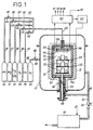
- FIG. 1 The installation illustrated in FIG. 1 is of the type described in the document WO 87/04733 already cited.
- the armature 10 is in the form of a cylinder with a vertical axis closed by tightly sealed by a bottom 10a at its bottom and a removable cover lOb to its upper part.
- the substrates to be densified are supported by a base plate 20 which can rotate around a vertical axis coincident with that of the armature 10 and the inductor 16. Additional plates 22, 24, supported by the plate 20 with interposition of spacers 25, allow load substrates on several levels, a total of three in the illustrated example.
- the rotation of the base plate 20 is controlled by means of a motor (not shown) coupled to a shaft 26 passing through the bottom wall of the enclosure 12 and the bottom 10a of the armature and fixed to the plate 20 on the underside of this one.
- the gaseous phase suitable for forming the material of the matrix intended to densify the substrates is admitted by a pipe 28 which terminates in the upper part of the chamber 14 through the cover 10b.
- the gas phase comprises a mixture of a gaseous precursor of the matrix material and HCl.
- the gaseous precursor depends on the nature of the matrix.
- the gaseous precursor is MTS added with H 2 .
- the gaseous precursor is a mixture of BCl 3 and a carbon precursor.
- the latter may be an alkane, an alkyl or an alkene, alone or as a mixture, for example a mixture of C 3 H 8 and CH 4 (or natural gas).
- the gaseous precursor is a mixture of MTS and BCl 3 added with H 2 .
- the gases MTS, BCl 3 , C 3 H 8 + CH 4 , H 2 and HCl come from sources 30, 31, 32, 33, 34 through supply lines 36, 37, 38, 39, 40 provided with injection valves 42, 43, 44, 45, 46 and leading to the pipe 28.
- the extraction of residual gases from chamber 14 is carried out by opening of a valve 48 which puts the chamber 14 in communication with a pumping device 50 through at least one discharge pipe 52.
- the pumping device 50 is for example a water ring pump.
- the pipe 52 communicates with the lower part of the chamber 14 through a annular passage 54 formed around the shaft 26.
- Signals produced by pressure 56 and temperature 58 sensors, representing the pressure and the temperature in the chamber 14, are transmitted to an automaton 60.
- the latter controls the pump 50 and the valve 48 to establish the desired pressure in the chamber 14 before admission of the gas phase and controls a generator 62 supplying the inductor 16 in order to maintain the temperature in the enclosure at the desired value.
- the controller 60 furthermore controls the valves 42, 43, 44, 45, 46 to adjust the respective flow rates of MTS, BCl 3 , CH 4 + C 3 H 8 , H 2 and HCl according to the predetermined composition of the phase carbonated.
- the gas phase entering the reaction chamber 14 reaches first of all in contact with preheating plates 64, for example in the form of superimposed perforated plates.
- preheating plates 64 being inside of the reaction chamber they are constantly at the temperature prevailing in this one. This allows the gas phase to be brought to the desired temperature before contact with the substrates to be densified.
- the volume located around the armature 10 inside the enclosure can be continuously swept by a neutral gas, such as nitrogen (N 2 ).
- a neutral gas such as nitrogen (N 2 ).
- N 2 nitrogen
- the nitrogen thus forms a buffer of neutral gas around the reaction chamber. It is extracted through a pipe 69 which terminates in the evacuation pipe 52 outside the enclosure 12.
- samples A, B, C and D are produced by stacking and progressive needling of bi-directional layers of carbon fibers, such as described in document FR-A-2 584 106. This texture is identical to that constituting preforms for brake discs of composite material carbon-carbon fitted to "Airbus" type aircraft.
- the substrate of sample E consists of a felt of partially densified carbon by vacuum suction of carbon powder, as described in document FR-A-2 671 797.
- a first series of three tests I, II, III was carried out with a temperature T in the reaction chamber of 1010 ° C., a Q (MTS) equal to 150 sccm (standard cm 3 / min.) And a Q (H 2 ) equal to 900 sccm, by giving the flow of HCl (Q (HCl)) values of 0, 37.5 and 75 sccm respectively, that is to say proportions successively equal to 0, 25 and 50% between HCl and MTS flow rates.
- a fourth test IV was carried out by doubling the Q (MTS) and Q (H 2 ) compared to test III, the other parameters being unchanged.
- test V was carried out under the same conditions as test IV, with the exception of the temperature T reduced from 1010 ° C to 950 ° C.
- test V A sixth VI test was carried out under the same conditions as test V, with the exception of the flow rate Q (HCl) doubled from 75 sccm to 150 sccm.
- the letters H, M, B identify the levels “high”, “medium” and “low” in the reaction chamber.
- results grouped in the preceding tables show indisputably the interest, to reduce the heterogeneity of SiC densification both in the volume of the oven than in the same room, to carry out infiltration chemical in vapor phase at relatively low temperature, preferably below 1000 ° C in the presence of HCl and increasing the flow rate of MTS.
- the chemical vapor infiltration process of SiC can be implemented with temperature gradient, for example by means of a installation as shown schematically in Figure 2.
- This installation is more particularly intended for densification annular preforms 100, such as brake disc preforms produced made of a heat conducting material, such as carbon in the form of fibers.
- the preforms are stacked around a central cylindrical graphite 110 core forming an armature, the assembly being supported by a fixed insulating plate 120.
- the preforms 100 can be slightly spaced from each other by means of spacers 102 to facilitate access of the gas phase to the main faces preforms.
- the reaction chamber 114 in which the armature and the preforms to be densified is delimited by an insulating wall 118, non-conductive of electricity, with a bottom 118a and a cover 118b.
- An inductor 116 surrounds the wall 118, the whole being inside an enclosure 112.
- the means for supplying the chamber 114 with the gas phase MTS + H 2 + HCl and for extracting the residual gases are similar to those of the installation in FIG. 1 and are not shown. Note however that the evacuation pipe 152 ends directly at the lower part of the chamber 114 through the bottom 118a. In addition, the chamber 114 is not provided with means for preheating the incoming gas phase.
- the armature 110 is heated by electromagnetic coupling with inductor 116. Heating of the annular preforms is carried out by contact of their internal cylindrical surfaces with the armature 110. A gradient is then established thermal between these internal surfaces and their exposed external surfaces, these being cooled by radiation and convection in contact with the gas phase having entered the room. This gradient depends in particular on the characteristics dimensional and thermal conductivity of the preforms.
- the generator 162 supplying the inductor 116 is controlled so that, at least at the start of the infiltration process, the temperature of the parts of the preforms adjacent to the armature are at a temperature well above the minimum temperature of SiC deposition, i.e. airc about 700 ° C. SiC densification is therefore done preferably in these parts of the preforms. This avoids densification too fast parts of the preforms close to their outer surfaces which could cause premature blockage of porosity, preventing densification to the core and generating a strong densification gradient within the parts obtained.
- the substrates 100 are heated by through the armature 110 with which they are in contact.
- armature 110 When nature conductive of substrates allows it (for example carbon or graphite substrates with a relatively high fiber content), at least a heating of the substrates partially by direct coupling with the inductor is possible, in which case the armature can possibly be omitted.
- the induced currents are established rather near the surface of the substrates, the thermal gradient is established desired due to the cooling of the exposed surfaces of the substrates by radiation and convection.
- the process according to the invention is suitable for chemical infiltration in the vapor phase of a material composed of carbon as well as silicon and / or boron in any type of substrate capable of withstanding the operating conditions and chemically compatible with the gas phase.
- the process can be used to densification by an exclusively constituted matrix or partially of this material.
- the matrix can be completed by one or more matrix phases made up of other deposited materials before and / or after the material composed of carbon as well as silicon and / or boron.
Landscapes
- Chemical & Material Sciences (AREA)
- Engineering & Computer Science (AREA)
- Ceramic Engineering (AREA)
- Materials Engineering (AREA)
- Organic Chemistry (AREA)
- Chemical Kinetics & Catalysis (AREA)
- Manufacturing & Machinery (AREA)
- Structural Engineering (AREA)
- Mechanical Engineering (AREA)
- Metallurgy (AREA)
- Chemical Vapour Deposition (AREA)
Claims (14)
- Verfahren zur chemischen Infiltration in der Dampfphase eines Materials, das aus Kohlenstoff sowie aus Silizium und/oder aus Bor besteht, ins Innere eines porösen Substrats mittels einer einen gasförmigen Vorläufer des Materials enthaltenden Gasphase,
dadurch gekennzeichnet,
daß die Infiltration bei einer Temperatur von höchstens gleich 1.050°C durchgeführt wird und die Gasphase außerdem Chlorwasserstoff (HCl) enthält. - Verfahren nach Anspruch 1,
dadurch gekennzeichnet,
daß der Volumenanteil von HCl bezogen auf den gasförmigen Vorläufer des Siliziums und/oder des Bors in der Gasphase mindestens gleich 25 % ist. - Verfahren nach Anspruch 1 oder 2,
dadurch gekennzeichnet,
daß die chemische Infiltration in der Dampfphase bei einer Temperatur unterhalb von 1.000°C durchgeführt wird. - Verfahren nach einem der Ansprüche 1 bis 3,
dadurch gekennzeichnet,
daß der gasförmige Vorläufer Methyltrichlorsilan (MTS) enthält. - Verfahren nach Anspruch 4,
dadurch gekennzeichnet,
daß der gasförmige Vorläufer außerdem einen Vorläufer von Bor enthält. - Verfahren nach Anspruch 4 oder 5,
dadurch gekennzeichnet,
daß die Gasphase außerdem Wasserstoff (H2) enthält. - Verfahren nach einem der Ansprüche 1 bis 6,
dadurch gekennzeichnet,
daß der gasförmige Vorläufer einen Vorläufer von Bor und einen Vorläufer von Kohlenstoff enthält. - Verfahren nach einem der Ansprüche 1 bis 7,
dadurch gekennzeichnet,
daß im Inneren des Substrats ein Temperaturgradient dergestalt hergestellt wird, daß es in den von seinen exponierten Oberflächen entfernten Bereichen eine höhere Temperatur aufweist als an diesen Oberflächen. - Verfahren nach Anspruch 8 zur Verdichtung von ringförmigen Substraten,
dadurch gekennzeichnet,
daß das Substrat um ein Induktionselement herum, mit dem es in Berührung ist, angeordnet wird, wobei das Erwärmen des Substrats verwirklicht wird durch die Berührung mit dem durch Kopplung mit einem Induktor erwärmten Induktionselement. - Verfahren nach Anspruch 8,
dadurch gekennzeichnet,
daß das Substrat aus einem leitfähigen Material besteht und zumindest teilweise durch Induktion mittels direkter Kopplung mit einem Induktor erwärmt wird. - Verfahren nach einem der Ansprüche 1 bis 10,
dadurch gekennzeichnet,
daß gleichzeitig eine chemische Infiltration in der Dampfphase ins Innere mehrerer Substrate, die im Inneren einer Reaktionskammer zwischen einem Einlaß für die Gasphase in die Kammer und einem Auslaß für Restgas aus der Kammer heraus angeordnet sind, durchgeführt wird. - Verfahren nach Anspruch 11,
dadurch gekennzeichnet,
daß das Strömen der Gasphase in der Kammer in einer genau vertikalen Richtung erfolgt, und die Substrate auf verschiedenen, vertikal beabstandeten Ebenen angeordnet sind. - Verfahren nach Anspruch 11,
dadurch gekennzeichnet,
daß das Strömen der Gasphase in der Kammer in einer genau vertikalen Richtung erfolgt und die Substrate stapelförmig angeordnet sind. - Verfahren nach Anspruch 13 zur Verdichtung von ringförmigen Substraten,
dadurch gekennzeichnet,
daß die Substrate stapelförmig um ein gemeinsames Induktionselement herum, mit dem sie in Berührung sind, angeordnet werden, wobei das Erwärmen der Substrate durch die Berührung mit dem mittels Kopplung mit einem Induktor erwärmten Induktionselement verwirklicht wird.
Applications Claiming Priority (3)
| Application Number | Priority Date | Filing Date | Title |
|---|---|---|---|
| FR9504381 | 1995-04-12 | ||
| FR9504381A FR2732962B1 (fr) | 1995-04-12 | 1995-04-12 | Procede pour l'infiltration chimique en phase vapeur d'un materiau compose de carbone et de silicium et/ou bore |
| PCT/FR1996/000561 WO1996032360A1 (fr) | 1995-04-12 | 1996-04-12 | Procede pour l'infiltration chimique en phase vapeur d'un materiau compose de carbone et de silicium et/ou bore |
Publications (2)
| Publication Number | Publication Date |
|---|---|
| EP0820424A1 EP0820424A1 (de) | 1998-01-28 |
| EP0820424B1 true EP0820424B1 (de) | 2000-07-19 |
Family
ID=9478032
Family Applications (1)
| Application Number | Title | Priority Date | Filing Date |
|---|---|---|---|
| EP96913580A Expired - Lifetime EP0820424B1 (de) | 1995-04-12 | 1996-04-12 | Verfahren zur chemischen dampfinfiltration eines aus kohlenstoff und silicium und/oder bor zusammengesetzten materials |
Country Status (7)
| Country | Link |
|---|---|
| EP (1) | EP0820424B1 (de) |
| JP (1) | JPH11503493A (de) |
| CA (1) | CA2217702A1 (de) |
| DE (1) | DE69609411T2 (de) |
| FR (1) | FR2732962B1 (de) |
| RU (1) | RU2158251C2 (de) |
| WO (1) | WO1996032360A1 (de) |
Families Citing this family (10)
| Publication number | Priority date | Publication date | Assignee | Title |
|---|---|---|---|---|
| DE19646094C2 (de) * | 1996-11-08 | 1999-03-18 | Sintec Keramik Gmbh | Verfahren zur chemischen Gasphaseninfiltration von refraktären Stoffen, insbesondere Kohlenstoff und Siliziumkarbid, sowie Verwendung des Verfahrens |
| DE102008052571A1 (de) * | 2007-10-25 | 2009-04-30 | Von Ardenne Anlagentechnik Gmbh | Diffusionsofen und Verfahren zur Temperaturführung |
| FR2950622B1 (fr) * | 2009-09-28 | 2011-10-21 | Snecma Propulsion Solide | Piece en materiau composite a matrice ceramique et procede pour sa fabrication. |
| DE102012100176B4 (de) | 2012-01-10 | 2016-11-17 | Cvt Gmbh & Co. Kg | Verfahren zur chemischen Gasphaseninfiltration von wenigstens einem refraktären Stoff |
| FR3007511B1 (fr) * | 2013-06-19 | 2017-09-08 | Herakles | Installation pour traitements thermiques de produits en materiau composite comprenant des moyens de mesure de temperature delocalises |
| JP6249815B2 (ja) | 2014-02-17 | 2017-12-20 | 株式会社Ihi | 耐熱複合材料の製造方法及び製造装置 |
| CA2933025C (en) | 2014-02-25 | 2019-01-15 | Ihi Corporation | Heat-resistant composite material production method and production device |
| RU2638610C2 (ru) * | 2016-03-29 | 2017-12-14 | Общество с ограниченной ответственностью "Оптогард Нанотех" (ООО "Оптогард Нанотех)" | Устройство для лазерно-плазменного синтеза высокотвердых микро- и наноструктурированных покрытий |
| FR3059679B1 (fr) * | 2016-12-07 | 2021-03-12 | Safran Ceram | Outillage de conformation et installation pour l'infiltration chimique en phase gazeuse de preformes fibreuses |
| FR3095213B1 (fr) * | 2019-04-19 | 2022-12-23 | Safran Ceram | Installation de densification CVI |
Family Cites Families (2)
| Publication number | Priority date | Publication date | Assignee | Title |
|---|---|---|---|---|
| FR2594119B1 (fr) * | 1986-02-10 | 1988-06-03 | Europ Propulsion | Installation pour l'infiltration chimique en phase vapeur d'un materiau refractaire autre que le carbone |
| FR2668477B1 (fr) * | 1990-10-26 | 1993-10-22 | Propulsion Ste Europeenne | Materiau composite refractaire protege contre la corrosion, et procede pour son elaboration. |
-
1995
- 1995-04-12 FR FR9504381A patent/FR2732962B1/fr not_active Expired - Fee Related
-
1996
- 1996-04-12 DE DE69609411T patent/DE69609411T2/de not_active Expired - Lifetime
- 1996-04-12 EP EP96913580A patent/EP0820424B1/de not_active Expired - Lifetime
- 1996-04-12 RU RU97118434/03A patent/RU2158251C2/ru not_active IP Right Cessation
- 1996-04-12 WO PCT/FR1996/000561 patent/WO1996032360A1/fr active IP Right Grant
- 1996-04-12 JP JP8530779A patent/JPH11503493A/ja active Pending
- 1996-04-12 CA CA002217702A patent/CA2217702A1/en not_active Abandoned
Also Published As
| Publication number | Publication date |
|---|---|
| CA2217702A1 (en) | 1996-10-17 |
| WO1996032360A1 (fr) | 1996-10-17 |
| DE69609411T2 (de) | 2001-03-01 |
| FR2732962B1 (fr) | 1997-07-04 |
| RU2158251C2 (ru) | 2000-10-27 |
| JPH11503493A (ja) | 1999-03-26 |
| FR2732962A1 (fr) | 1996-10-18 |
| EP0820424A1 (de) | 1998-01-28 |
| DE69609411D1 (de) | 2000-08-24 |
Similar Documents
| Publication | Publication Date | Title |
|---|---|---|
| EP0946461B1 (de) | Verdichtung ringförmig angeordneter poröser substrate mittels chemicher dampfinfiltration mit temperaturgradient | |
| EP0821744B1 (de) | Verfahren zur chemischen infiltration in der gasphase, zur verdichtung poröser rotationssymmetrischer substratstapeln | |
| EP0725767B1 (de) | Verfahren zur chemischen dampfphaseninfiltration von material ins innere eines porösen substrates mit kontrollierter oberflächentemperatur | |
| EP1851358B1 (de) | Verfahren zur verdichtung von dünnen porösen substraten mittels chemischer infiltration in der dampfphase und vorrichtung zur beladung derartiger substrate | |
| EP0817762B1 (de) | Durch selbstheilende matrix oxidationsgeschütztes verbundmaterial und verfahren zu seiner herstellung | |
| EP1458902B1 (de) | Verfahren und vorrichtung zur verdichtung poröser substrate mittels chemischer dampfinfiltration | |
| EP0819105B1 (de) | Verfahren zur chemischen dampfinfiltration mit variablen infiltrationsparametern | |
| EP1370707B1 (de) | Verfahren zur verdichtung poröser substrate, mit einem zentralen durchgang, mittels chemischer dampfinfiltration | |
| EP1620577B1 (de) | Steuerung oder modelierung von verfahren zur verdichtung von porösen substraten mit kohlenstoff mittels chemischen gasphaseninfiltration | |
| EP1466031B1 (de) | Verfahren und vorrichtung zur verdichtung von substraten mittels chemischer gasphaseninfiltration | |
| EP0820424B1 (de) | Verfahren zur chemischen dampfinfiltration eines aus kohlenstoff und silicium und/oder bor zusammengesetzten materials | |
| FR2886640A1 (fr) | Procede et preforme pour la realisation de pieces en materiau composite par densification cvi et pieces obtenues | |
| WO2015136193A1 (fr) | Installation de densification cvi comprenant une zone de prechauffage a forte capacite. | |
| FR2670507A1 (fr) | Procede d'infiltration chimique en phase vapeur. | |
| EP2875167B1 (de) | Chemische gasphaseninfiltrationsvorrichtung mit hoher beladungskapazität | |
| EP2110458B1 (de) | Wärmebehandlungsofen mit Induktionsheizung | |
| WO2007003813A2 (fr) | Procede de densification rapide d'un substrat poreux par formation d'un depot solide au sein de la porosite du substrat | |
| WO2020212168A1 (fr) | Installation de densification cvi | |
| WO2024161078A1 (fr) | Preforme pour densification cvi a flux dirige | |
| WO2023105139A1 (fr) | Installation d'infiltration chimique en phase gazeuse a double chambre de reaction | |
| WO2024100352A1 (fr) | Installation d'infiltration chimique en phase gazeuse a double traitement |
Legal Events
| Date | Code | Title | Description |
|---|---|---|---|
| PUAI | Public reference made under article 153(3) epc to a published international application that has entered the european phase |
Free format text: ORIGINAL CODE: 0009012 |
|
| 17P | Request for examination filed |
Effective date: 19971010 |
|
| AK | Designated contracting states |
Kind code of ref document: A1 Designated state(s): DE FR GB |
|
| RAP1 | Party data changed (applicant data changed or rights of an application transferred) |
Owner name: SOCIETE NATIONALE D'ETUDE ET DE CONSTRUCTION DE MO |
|
| GRAG | Despatch of communication of intention to grant |
Free format text: ORIGINAL CODE: EPIDOS AGRA |
|
| GRAG | Despatch of communication of intention to grant |
Free format text: ORIGINAL CODE: EPIDOS AGRA |
|
| GRAG | Despatch of communication of intention to grant |
Free format text: ORIGINAL CODE: EPIDOS AGRA |
|
| GRAH | Despatch of communication of intention to grant a patent |
Free format text: ORIGINAL CODE: EPIDOS IGRA |
|
| 17Q | First examination report despatched |
Effective date: 19990330 |
|
| GRAH | Despatch of communication of intention to grant a patent |
Free format text: ORIGINAL CODE: EPIDOS IGRA |
|
| GRAA | (expected) grant |
Free format text: ORIGINAL CODE: 0009210 |
|
| AK | Designated contracting states |
Kind code of ref document: B1 Designated state(s): DE FR GB |
|
| REF | Corresponds to: |
Ref document number: 69609411 Country of ref document: DE Date of ref document: 20000824 |
|
| GBT | Gb: translation of ep patent filed (gb section 77(6)(a)/1977) |
Effective date: 20001012 |
|
| PLBE | No opposition filed within time limit |
Free format text: ORIGINAL CODE: 0009261 |
|
| STAA | Information on the status of an ep patent application or granted ep patent |
Free format text: STATUS: NO OPPOSITION FILED WITHIN TIME LIMIT |
|
| 26N | No opposition filed | ||
| REG | Reference to a national code |
Ref country code: GB Ref legal event code: IF02 |
|
| REG | Reference to a national code |
Ref country code: FR Ref legal event code: TP Ref country code: FR Ref legal event code: CD |
|
| PGFP | Annual fee paid to national office [announced via postgrant information from national office to epo] |
Ref country code: GB Payment date: 20100329 Year of fee payment: 15 |
|
| PGFP | Annual fee paid to national office [announced via postgrant information from national office to epo] |
Ref country code: FR Payment date: 20100413 Year of fee payment: 15 |
|
| PGFP | Annual fee paid to national office [announced via postgrant information from national office to epo] |
Ref country code: DE Payment date: 20100407 Year of fee payment: 15 |
|
| REG | Reference to a national code |
Ref country code: DE Ref legal event code: R119 Ref document number: 69609411 Country of ref document: DE |
|
| REG | Reference to a national code |
Ref country code: DE Ref legal event code: R119 Ref document number: 69609411 Country of ref document: DE |
|
| GBPC | Gb: european patent ceased through non-payment of renewal fee |
Effective date: 20110412 |
|
| REG | Reference to a national code |
Ref country code: FR Ref legal event code: ST Effective date: 20111230 |
|
| PG25 | Lapsed in a contracting state [announced via postgrant information from national office to epo] |
Ref country code: FR Free format text: LAPSE BECAUSE OF NON-PAYMENT OF DUE FEES Effective date: 20110502 |
|
| PG25 | Lapsed in a contracting state [announced via postgrant information from national office to epo] |
Ref country code: GB Free format text: LAPSE BECAUSE OF NON-PAYMENT OF DUE FEES Effective date: 20110412 |
|
| PG25 | Lapsed in a contracting state [announced via postgrant information from national office to epo] |
Ref country code: DE Free format text: LAPSE BECAUSE OF NON-PAYMENT OF DUE FEES Effective date: 20111031 |