EP0817397B1 - Verfahren zur Schaltung eines Kanals von einem ersten auf einen zweiten Übertragungsweg - Google Patents
Verfahren zur Schaltung eines Kanals von einem ersten auf einen zweiten Übertragungsweg Download PDFInfo
- Publication number
- EP0817397B1 EP0817397B1 EP97401515A EP97401515A EP0817397B1 EP 0817397 B1 EP0817397 B1 EP 0817397B1 EP 97401515 A EP97401515 A EP 97401515A EP 97401515 A EP97401515 A EP 97401515A EP 0817397 B1 EP0817397 B1 EP 0817397B1
- Authority
- EP
- European Patent Office
- Prior art keywords
- channel
- station
- communication
- following
- current
- Prior art date
- Legal status (The legal status is an assumption and is not a legal conclusion. Google has not performed a legal analysis and makes no representation as to the accuracy of the status listed.)
- Expired - Lifetime
Links
Images


Classifications
-
- H—ELECTRICITY
- H04—ELECTRIC COMMUNICATION TECHNIQUE
- H04B—TRANSMISSION
- H04B7/00—Radio transmission systems, i.e. using radiation field
- H04B7/14—Relay systems
- H04B7/15—Active relay systems
- H04B7/185—Space-based or airborne stations; Stations for satellite systems
- H04B7/1853—Satellite systems for providing telephony service to a mobile station, i.e. mobile satellite service
- H04B7/18539—Arrangements for managing radio, resources, i.e. for establishing or releasing a connection
- H04B7/18541—Arrangements for managing radio, resources, i.e. for establishing or releasing a connection for handover of resources
-
- H—ELECTRICITY
- H04—ELECTRIC COMMUNICATION TECHNIQUE
- H04B—TRANSMISSION
- H04B1/00—Details of transmission systems, not covered by a single one of groups H04B3/00 - H04B13/00; Details of transmission systems not characterised by the medium used for transmission
- H04B1/74—Details of transmission systems, not covered by a single one of groups H04B3/00 - H04B13/00; Details of transmission systems not characterised by the medium used for transmission for increasing reliability, e.g. using redundant or spare channels or apparatus
-
- H—ELECTRICITY
- H04—ELECTRIC COMMUNICATION TECHNIQUE
- H04L—TRANSMISSION OF DIGITAL INFORMATION, e.g. TELEGRAPHIC COMMUNICATION
- H04L1/00—Arrangements for detecting or preventing errors in the information received
- H04L1/22—Arrangements for detecting or preventing errors in the information received using redundant apparatus to increase reliability
Definitions
- the present invention generally relates to a method of switching, from a first propagation path to a second propagation path, a channel established between a first station and a second station.
- the invention applies, for example, to a satellite telecommunications network with mobiles operating in said switched diversity mode, according to which a communication established between a first station, for example a base station, and a second station, for example a mobile terminal, can be transmitted according to one of the two propagation paths respectively via two separate satellites.
- the invention can also be applied to a terrestrial radio network.
- a satellite telecommunications network embodying the invention comprises, on the one hand, switching and control units of base stations 2 connected via PCM links to the RTC Switched Telephone Network, and, on the other hand, multiple access base stations 3 connected in cluster to said units.
- the units 2 are responsible for routing communications from and to the mobile terminals 6 in a given geographical area, and for controlling one or more base stations 3.
- the base stations 3 provide in particular the transmission / radio reception of communications to / from mobile terminals 6.
- a communication, or channel, established with a mobile terminal 6 is selectively conveyed along one of at least two propagation paths 4A and 5A.
- the selection of one of these propagation paths results from a minimization of the transmitted satellite power for the communication considered.
- the communication established with the mobile terminal 6 is switched to that of the two propagation paths, 4A or 5A, respectively associated with the two satellites 4 and 5, which offers a minimum transmitted satellite power for a given transmission quality.
- the two propagation paths define between them, in view of the terminal, a difference in time, equal to the time difference between respective reception instants of data transmitted in synchronism along the two propagation paths 4A and 5A. Accordingly, this propagation path switching procedure must be associated with a terminal synchronization procedure.
- GSM Global System for Mobile Communications
- the next base station measures, in response to the receipt of this access message, a propagation delay between itself and the mobile terminal, and transmits to the terminal information relating to a time advance that the terminal must to apply to its clock with respect to what it believes to be the clock of the next station, so that the communication data transmitted by the terminal is received by the next base station synchronized temporally in a time interval of a frame received by the latter taking into account the distance between the following base station and terminal.
- the document EP 0 504 122 describes a cell change assisted by neighboring cells in a cellular communication system.
- this solution of the prior art proves to be inefficient. Indeed, in such a network, the small power margin allocated to each communication, in order to guarantee a minimum communication quality, leads to a rapid degradation of the communication in the presence for example of an obstacle. This rapid character of channel degradation also applies to control channels. This can then lead to an impossibility of reception by the terminal of a request message for switching a channel from a first propagation path to a second propagation path, and consequently to a loss of communication.
- the aim of the invention is to remedy this drawback by providing a particularly advantageous propagation path switching method, for example in the context of a satellite network.
- the method comprises a step of calculating in the second station a total time difference between the current channel and the following channel as a function of a part, (a) - of a time difference between two respective reception instants of control packets transmitted by the first station respectively according to the two propagation paths and, on the other hand, (b) - of a time advance which is a function of the distance between said second station and said first station.
- a first station for carrying out the method of the invention comprises means for allocating transmission and reception means to the current channel, and is characterized in that it comprises means for reserving transmission means and receiving at the next channel.
- a second station for implementing the method is characterized in that it comprises means for detecting a fault of reception of information in the current channel, and means for switching, in transmission and reception, said communication towards said channel next in response to a detection, by said means for detecting, of a reception error of information in said current channel.
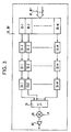
- a base station 3 embodying the invention comprises a central unit 39, two transmission chains 36 and 36 ', two reception channels 38 and 38'. An output of the transmission channel 36 and an input of the reception channel 38 are coupled to a first antenna 37a pointing to the satellite 4. An output of the transmission channel 36 'and an input of the reception channel 38 are coupled to a second antenna 37b pointing to the satellite 5.
- the central unit 39 in addition to an interface function with the base station switching and control unit 2, provides channel routing, time advance calculation and channel switching functions between propagation paths 4A and 5A.
- This central unit is connected to the transmission channel 36 through a transmission bus B1, to the transmission channel 36 'through a transmission bus B1', to the reception channel 38 through a reception bus B2 and to the transmission channel receiving 38 'through a B2' receiving bus.
- each transmission channel 36, 36 comprises M transmission queues 30-1 to 30 -M, respective outputs of which are applied to inputs of M interleaving and coding units 31-1 to 31- Mr. Respective outputs of these M interleaving and coding units 31-1 to 31-M are applied to inputs of M QPSK modulation units 32-1 to 32-M. Respective outputs of these M QPSK modulation units 32-1 to 32-M are applied to respective inputs of M PN / Hadamard modulation units 33-1 to 33-M.
- the purpose of this encoder is to implement a coding that provides a guarantee of the quality of the link.
- Such a coding circuit is well known to those skilled in the art.
- the baseband data packets from a 30-m queue are encoded and then interleaved by the 31-m unit.
- the resulting interlaced signal is modulated in QPSK (Quadrature Phase Shift Keying) by the 32-m unit.
- QPSK Quadratture Phase Shift Keying
- the operation of the network is such that all the signals transmitted inside a cell (terrestrial network) or a beam (satellite network) use the same PN sequence (Pseudo-Noise) which is different from a PN sequence used by a neighbor cell or beam.
- a signal to a particular station, such as terminal is further encoded by a particular one of a plurality of orthogonal sequences.
- PN sequences consist of identical pseudo-random sequences that are temporally shifted between them for separate cells.
- Orthogonal sequences are for example Walsh functions, also known as "Hadamard sequences”.
- a Hadamard Hm sequence, m between 1 and M, is a respective one of the M lines of the Hadamard matrix.
- a Hadamard matrix of rank M thus contains M sequences, each having a length of M bits.
- Hadamard sequences of order M have the property that over an interval of M symbols, the correlation between the different sequences is zero, it being understood that these different sequences are temporally aligned. it results from the fact that each sequence differs from any other sequence for half of the bits that compose it.
- the two QPSK quadrature modulated signal components are both multiplied by a rank m H-Hadamard sequence and a PN sequence associated with the beam. F4, F5, to produce two quadrature signals modulated by code.
- the different quadrature signals from the different code modulation units 33-1 to 33-M are added by means of the adder 34.
- the multiplier 35 By means of the multiplier 35, the resulting addition signal is modulated by a transmission carrier. P before being amplified by the amplifier 35 'to be transmitted through the antenna 37a, 37b.
- This addition signal, or composite signal, transmitted through the antenna 37a, 37b is as shown in FIG. figure 5 . It uses, for example, an elementary frame pattern at four time intervals itl-it4 which repeats at the frame rate.
- a TCH communication channel established in the network described herein is defined by a time interval itj, j between 1 and 4, a Hadamard Hm sequence, and a PN code.
- each reception channel 38, 38 comprises an RF amplifier 40, a multiplier 41, a filter 42, an IF amplifier 43, an analog / digital converter 44, an output of which applies to respective inputs of the M demodulation units by code 45-1 to 45-M.
- M decoding and deinterleaving units 47-1 to 47-M receive on respective inputs the outputs of the M code demodulation units 45-1 to 45-M, and M queues 48-1 to 48-M receive in entrance the outputs respective M decoding and deinterleaving units 47-1 to 47-M.
- the base station allocates to the terminal a SACCH channel in which is conveyed time advance information that said terminal must give to its clock with respect to what it believes to be the clock of the base station, of so that the data subsequently transmitted by the terminal coincide with a given time interval of the frame.
- Time advance information will in our realization have a much higher accuracy than the GSM, to account for the modulation CDMA. A number of bits higher than those defined for this purpose in the GSM will therefore be used in the SACCH.
- the base station 3 therefore receives the different channels over perfectly synchronized time intervals, and modulated by Hadamard sequences, as shown in FIG. figure 5 illustrating M frame signals relating to a beam or a cell.
- these different signals are successively amplified RF by the amplifier 40, demodulated in the multiplier 41 by a demodulation carrier P produced by a generator (not shown), filtered bandpass by the filter 42, amplified IF 43, and undergo an analog / digital conversion 44.
- the composite signal from the analog / digital converter 44 is applied to the respective inputs of the M demodulation units by code 33-1 to 33- Mr.
- Each 45-m code demodulation unit, m between 1 and M comprises in cascade a QPSK / PN correlator and a fast Hadamard transform.
- a signal from a code demodulation unit is applied to a respective one of the 47-m decoding and deinterleaving units.
- the baseband signal from each 47-m decoding and deinterleaving unit is applied in a respective queue 48-1 to be read and routed by the CPU 39 to a switching unit and to base station control 2.
- each terminal operates in a temporal duplexing mode.
- a reception window corresponding to a time slot it1 to it4, and a transmission window separated temporally from the reception window, these two windows occupying together less than one frame duration T.
- the two satellites 4 and 5 define two coverage areas, or beams, respectively F4 and F5 defined by two different PN codes.
- the transmit and receive channels 36 and 36 are associated with the coverage area F4 while the transmit and receive channels 36 'and 38' are associated with the coverage area F5.
- a given terminal 6 is in both the F4 coverage area of the satellite 4 and in the F5 coverage area of the satellite 5.
- Each transmission channel 36 and 36 'in the base station 3 transmits continuously, at the frame rate, in a given time interval, here it1, of one of the M frame signals associated with a respective Hadamard sequence, here H1, a control channel said BCCH general information broadcast.
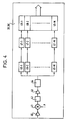
- the terminal, or second station, 6 comprises two code demodulation units 60 and 61, a code modulation unit 63 and a central unit 62.
- the two code demodulation units 60 and 61 receive through the antenna of the terminal 6, the composite signals respectively transmitted by the two transmission channels 36 and 36 'in the base station 3 ( FIG.7 , ET1).
- the demodulation unit 60 acquires the synchronization of PN and Hadamard codes relative to the frame signal carrying the BCCH channel transmitted by the transmission channel 36 of the base station 3.
- the demodulation unit 61 acquires the synchronization of PN and Hadamard codes relating to the frame signal carrying the BCCH channel transmitted by the transmission channel 36 'of the base station 3.
- At the output of these two code demodulation units 60 and 61, respectively, are produced the two baseband BCCH channel signals received via the satellites 4 and 5.
- BCCH channel signals are applied to the central unit 62.
- the latter periodically measures a value representative of a signal-to-noise ratio, for example a power level or a bit error rate, for each of these two BCCH channel signals respectively received according to the two propagation paths 4A and 5A ( FIG.7 , ET3).
- a signal-to-noise ratio for example a power level or a bit error rate
- the central unit 62 measures a time difference ⁇ t between these two BCCH channels, which are transmitted in synchronism along the two propagation paths 4A and 5A, respectively by the transmission channels 36 and 36 'in the transmission station. base 3 ( FIG.7 , ET2).
- this time difference difference ⁇ t can take a longer than a frame duration, it is expected that a BCCH channel vehicle, as is provided for other reasons in the GSM Recommendations, a frame rank information.
- the central unit 62 measures a time difference ⁇ t between the two BCCH channels by adding an apparent time difference and a time difference equal to the difference of the frame ranks in the two BCCH channels multiplied by the duration of frame T.
- the terminal For the establishment of a communication, whether outgoing or incoming, the terminal transmits in a so-called RACH channel, an access request message ( FIG.7 , ET5) through the code modulation unit 63. This message is issued immediately after receiving a BCCH channel signal. In the case of an incoming call, this transmission of an access request message by the terminal is preceded by the reception by the latter of an incoming call message in the two BCCH channels of the two composite signals received respectively. via the two propagation paths. In the RACH access request message is included information identifying that of the propagation paths 4A, 5A which offers a representative value of the highest signal-to-noise ratio.
- This propagation path is identified as a result of the periodic measurement by the central unit 62 of a value representative of a signal-to-noise ratio for each of these two BCCH channel signals respectively received according to the two propagation paths 4A and 5A. .
- the RACH access request message is transmitted on the return path of the propagation path providing a representative value of the highest signal-to-noise ratio ( FIG.7 , ET4).
- the base station 3 On receiving this access request message from the terminal, the base station 3 measures twice the terminal-base station delay. In response, the base station allocates to the mobile a SACCH channel ( FIG.7 , ET6) in which is conveyed time advance information TA that the mobile must give its clock in relation to what it believes to be the clock of the base station, so that the data subsequently transmitted by the mobile coincide with a given time interval itl to it4 of a received frame signal by the base station 3. This time advance is a function of the distance between the terminal and the base station.
- the base station 3 allocates to the terminal 6 a TCH communication channel in the form of a time slot range it1 to it4 and a Hadamard sequence H1 to H64, the terminal having already acquired by PN code synchronization.
- This channel is for example established according to the propagation path 4A and uses in the base station 3 to the transmission units 36 and reception unit 38.
- an associated TCH channel is reserved for the terminal 6 for the propagation path 5A, this channel using the units transmission 36 'and receiving unit 38' in the base station 3.
- resources useful for the transmission and reception of the associated channel TCH are reserved in the units 36 'and 38' by the unit 39
- Information necessary for the identification of this associated TCH channel is transmitted from station 3 to terminal 6.
- the terminal During the communication, initially established according to the propagation path 4A, the terminal periodically transmits in the SACCH channel the values representative of signal-to-noise ratio which are periodically measured by the central unit 63 for each of these two respectively received BCCH channel signals. following the two propagation paths 4A and 5A. Based on these values, the base station makes the decision to switch the current communication channel conveyed in the current TCH channel to the channel Associated TCH, or next channel. This switching is performed without informing the terminal 6. In the latter, the central unit 62 detecting an information reception fault in the current TCH channel which is allocated to the terminal 6, then takes the initiative to switch, or switch , in transmission and reception on the associated TCH channel ( FIG.7 , ET7).
- This switching of the current channel to the next associated channel leads in the terminal 6 to a resynchronization as a result of the difference in time between the two propagation paths 5A and 5B.
- This resynchronization is performed by the terminal as a function of the time advance information TA and of the time difference ⁇ t stored in the central unit 62. To do this, it adds these two pieces of information expressed in algebraic value in order to deduce therefrom a time difference. total ( FIG.7 , ET8).
- the next channel then becomes a current channel and the current channel becomes a next channel.
- the invention is not limited to the embodiment described and can be extended to all types of telecommunications networks.
Landscapes
- Engineering & Computer Science (AREA)
- Computer Networks & Wireless Communication (AREA)
- Signal Processing (AREA)
- Physics & Mathematics (AREA)
- Astronomy & Astrophysics (AREA)
- Aviation & Aerospace Engineering (AREA)
- General Physics & Mathematics (AREA)
- Mobile Radio Communication Systems (AREA)
- Detection And Prevention Of Errors In Transmission (AREA)
- Monitoring And Testing Of Transmission In General (AREA)
- Radio Relay Systems (AREA)
Claims (5)
- Verfahren zur Schaltung einer zwischen einer ersten Station (3) und einer zweiten Station (6) aufgebauten Verbindung von einem aktuellen Übertragungsweg (4A) auf einen folgenden Übertragungsweg (5A), wobei das besagte Verfahren die folgenden Schritte umfasst:- Messen eines für den Signal-Rausch-Abstand repräsentativen Wertes für einen jeden der besagten aktuellen und folgenden Übertragungswege,- Schalten, durch die erste Station (3), der Verbindung von einem aktuellen Kanal entsprechend dem aktuellen Übertragungsweg (4A) auf einen folgenden Kanal entsprechend einem folgenden Übertragungsweg (5A), gemäß den für den Signal-Rausch-Abstand repräsentativen Werten, welche jeweils für den besagten aktuellen Übertragungsweg und den besagten folgenden Übertragungsweg gemessen wurden,dadurch gekennzeichnet:- dass der besagte folgende Kommunikationskanal für die besagte Verbindung reserviert ist, und durch den Schritt des- Schaltens, in der besagten zweiten Station (3), der besagten Verbindung von dem aktuellen Kanal auf den folgenden Kanal im Anschluss an einen Empfangsfehler der Verbindung in dem aktuellen Kanal.
- Verfahren nach Anspruch 1, gekennzeichnet durch einen Sende-/Empfangsmodus von Kanälen vom Typ TDMA, und durch den Schritt des Berechnens, in der zweiten Station (6), einer Gesamt-Time-Walk-Differenz zwischen dem besagten aktuellen Kanal und dem besagten folgenden Kanal in Abhängigkeit von einerseits, (a) - einer Time-Walk-Differenz (Δt) zwischen zwei jeweiligen Empfangsmomenten von von der ersten Station (3) ausgegeben Kontrollpaketen, welche jeweils den zwei Übertragungswegen (4A, 5A) folgen, und andererseits, (b) - eines Zeitfortschritts (TA), welcher von der Entfernung zwischen der besagten zweiten Station und der besagten ersten Station abhängt.
- Erste Station zum Ausführen des Verfahrens nach Anspruch 1 oder 2, mit Mitteln für die Zuteilung von Sende- und Empfangsmitteln (36, 38) an den aktuellen Kanal, dadurch gekennzeichnet, dass sie Mittel (39) für das Reservieren von Sende- und Empfangsmitteln (36', 38') für den folgenden Kanal umfasst.
- Zweite Station zum Ausführen des Verfahrens nach Anspruch 1, dadurch gekennzeichnet, dass Mittel für die Detektion eines Informationsempfangsfehlers im aktuellen Kanal umfasst, sowie Mittel zum Schalten, im Sende- und im Empfangsmodus, der besagten Verbindung an den folgenden Kanal im Anschluß an die Detektion, durch die besagten Detektionsmittel, eines Informationsempfangsfehlers in dem besagten aktuellen Kanal.
- Zweite Station nach Anspruch 4 zum Ausführen des Verfahrens nach Anspruch 2, dadurch gekennzeichnet, dass sie weiterhin Mittel zum Berechnen, einer Gesamt-Time-Walk-Differenz zwischen dem besagten aktuellen Kanal und dem besagten folgenden Kanal in Abhängigkeit von einerseits (a) - einer Time-Walk-Differenz zwischen zwei jeweiligen Empfangsmomenten von von der ersten Station (3) ausgegeben Kontrollpaketen, welche jeweils den zwei Übertragungswegen (4A, 5A) folgen, und andererseits, (b) - eines Zeitfortschritts (TA), welcher von der Entfernung zwischen der besagten zweiten Station und der besagten ersten Station abhängt.
Applications Claiming Priority (2)
| Application Number | Priority Date | Filing Date | Title |
|---|---|---|---|
| FR9608339A FR2750820B1 (fr) | 1996-07-04 | 1996-07-04 | Procede de commutation d'un canal d'un premier chemin de propagation vers un second chemin de propagation |
| FR9608339 | 1996-07-04 |
Publications (2)
| Publication Number | Publication Date |
|---|---|
| EP0817397A1 EP0817397A1 (de) | 1998-01-07 |
| EP0817397B1 true EP0817397B1 (de) | 2008-12-31 |
Family
ID=9493712
Family Applications (1)
| Application Number | Title | Priority Date | Filing Date |
|---|---|---|---|
| EP97401515A Expired - Lifetime EP0817397B1 (de) | 1996-07-04 | 1997-06-30 | Verfahren zur Schaltung eines Kanals von einem ersten auf einen zweiten Übertragungsweg |
Country Status (5)
| Country | Link |
|---|---|
| US (1) | US5995807A (de) |
| EP (1) | EP0817397B1 (de) |
| CA (1) | CA2209476C (de) |
| DE (1) | DE69739182D1 (de) |
| FR (1) | FR2750820B1 (de) |
Families Citing this family (11)
| Publication number | Priority date | Publication date | Assignee | Title |
|---|---|---|---|---|
| US6091760A (en) * | 1998-06-29 | 2000-07-18 | L-3 Communications Corporation | Non-recursively generated orthogonal PN codes for variable rate CDMA |
| US6320843B1 (en) | 1998-11-18 | 2001-11-20 | Ericsson Inc. | Wireless communications systems with standard and robust services and methods of operation thereof |
| US6332006B1 (en) | 1998-11-18 | 2001-12-18 | Ericsson Inc. | Apparatus and methods for providing high-penetration messaging in wireless communications systems |
| US6324395B1 (en) | 1998-11-18 | 2001-11-27 | Ericsson Inc. | Apparatus and methods for assigning spectral and non-spectral resource charges in wireless communications systems |
| US6628945B1 (en) | 1999-04-20 | 2003-09-30 | Ericsson Inc. | Apparatus and methods for high-penetration random access in wireless communications systems |
| US6405039B1 (en) | 1999-04-20 | 2002-06-11 | Ericsson Inc. | Apparatus and methods for allocation of high-penetration services in wireless communications systems |
| GB2356771A (en) * | 1999-11-24 | 2001-05-30 | Motorola Ltd | Signal measurement in a second capsule within a cell by a first capsule whilst it is servicing a call |
| FR2817419A1 (fr) * | 2000-11-24 | 2002-05-31 | Cit Alcatel | Procede et systeme de telecommunication multimedia par satellites |
| US7099277B2 (en) | 2002-02-20 | 2006-08-29 | Mitsubishi Electric Research Laboratories, Inc. | Dynamic optimal path selection in multiple communications networks |
| JP4411166B2 (ja) * | 2004-09-21 | 2010-02-10 | 株式会社ケンウッド | 無線通信システム、無線通信制御装置、無線通信装置及び無線通信方法 |
| US11528077B2 (en) * | 2019-06-25 | 2022-12-13 | Ast & Science, Llc | Selection, diversity combining or satellite MIMO to mitigate scintillation and/or near-terrestrial multipath to user devices |
Citations (1)
| Publication number | Priority date | Publication date | Assignee | Title |
|---|---|---|---|---|
| EP0504122A2 (de) * | 1991-03-15 | 1992-09-16 | Telefonaktiebolaget L M Ericsson | Nachbar-Zellen-unterstütztes Weiterreichen in Zellular-Kommunikationssystem |
Family Cites Families (12)
| Publication number | Priority date | Publication date | Assignee | Title |
|---|---|---|---|---|
| DE3420365A1 (de) * | 1984-06-01 | 1985-12-05 | Brown, Boveri & Cie Ag, 6800 Mannheim | Verfahren zur umschaltung zwischen redundanten uebertragungswegen |
| US5001776A (en) * | 1988-10-27 | 1991-03-19 | Motorola Inc. | Communication system with adaptive transceivers to control intermodulation distortion |
| US5189734A (en) * | 1988-11-16 | 1993-02-23 | U.S. Philips Corporation | Cellular radio system |
| US5101501A (en) * | 1989-11-07 | 1992-03-31 | Qualcomm Incorporated | Method and system for providing a soft handoff in communications in a cdma cellular telephone system |
| JP2679442B2 (ja) * | 1991-04-17 | 1997-11-19 | 日本電気株式会社 | ディジタル移動通信方式 |
| DE4308161C2 (de) * | 1993-03-16 | 2000-12-14 | Philips Corp Intellectual Pty | System zur Nachrichtenübertragung über Satelliten |
| US5432843A (en) * | 1993-08-02 | 1995-07-11 | Motorola Inc. | Method of performing handoff in a cellular communication system |
| JP3222001B2 (ja) * | 1993-12-14 | 2001-10-22 | ユニデン株式会社 | チャンネル切替制御方法およびそれを用いたコードレス電話機 |
| US5574968A (en) * | 1994-06-01 | 1996-11-12 | Motorola, Inc. | Satellite cellular communication methods for performing cell-to-cell handoff |
| DE69532939T2 (de) * | 1994-07-18 | 2005-06-16 | Nippon Telegraph And Telephone Corp. | Eine störungsfreie Wegumschaltungsanordnung und Verfahren |
| US5710791A (en) * | 1994-10-27 | 1998-01-20 | Northern Telecom Limited | Methods and apparatus for predicting voice quality in AMPS cellular radio systems |
| US5722073A (en) * | 1996-02-21 | 1998-02-24 | Telefonaktiebolaget L M Ericsson | Method and system for measuring signals in a telecommunications systemhaving maho |
-
1996
- 1996-07-04 FR FR9608339A patent/FR2750820B1/fr not_active Expired - Fee Related
-
1997
- 1997-06-30 DE DE69739182T patent/DE69739182D1/de not_active Expired - Lifetime
- 1997-06-30 EP EP97401515A patent/EP0817397B1/de not_active Expired - Lifetime
- 1997-07-02 US US08/887,287 patent/US5995807A/en not_active Expired - Lifetime
- 1997-07-03 CA CA002209476A patent/CA2209476C/fr not_active Expired - Fee Related
Patent Citations (1)
| Publication number | Priority date | Publication date | Assignee | Title |
|---|---|---|---|---|
| EP0504122A2 (de) * | 1991-03-15 | 1992-09-16 | Telefonaktiebolaget L M Ericsson | Nachbar-Zellen-unterstütztes Weiterreichen in Zellular-Kommunikationssystem |
Also Published As
| Publication number | Publication date |
|---|---|
| FR2750820B1 (fr) | 1999-04-02 |
| CA2209476A1 (fr) | 1998-01-04 |
| CA2209476C (fr) | 2004-05-25 |
| DE69739182D1 (de) | 2009-02-12 |
| US5995807A (en) | 1999-11-30 |
| FR2750820A1 (fr) | 1998-01-09 |
| EP0817397A1 (de) | 1998-01-07 |
Similar Documents
| Publication | Publication Date | Title |
|---|---|---|
| EP0095959B1 (de) | Funkverbindungssystem nach dem Frequenzsprungverfahren | |
| EP0801870B1 (de) | Verfahren und gerät zur verwendung der gesamten spektralen sendeleistung in einem spreizspektrumübertragungssystem zur energie- und phasenzeitnachführung einzelner empfänger | |
| EP0630120B1 (de) | Synchronisationsverfahren in Funktelefonkommunikationen mit Kodemultiplex-Vielfachzugriff | |
| EP0931429B1 (de) | Verfahren und vorrichtung zur interferenzanalyse in einem zellularen mobilkommunikationssystem | |
| FI114594B (fi) | Monen käyttäjän tietoliikennejärjestelmäarkkitehtuuri, johon kuuluu hajautettuja vastaanottimia | |
| FR2751495A1 (fr) | Systeme de telecommunications a synchronisation temporelle | |
| EP0817397B1 (de) | Verfahren zur Schaltung eines Kanals von einem ersten auf einen zweiten Übertragungsweg | |
| FR2737362A1 (fr) | Procede de selection des retards de propagation retenus pour recevoir des messages transmis par radiocommunication a etalement de spectre | |
| FR2770708A1 (fr) | Procede et dispositif pour le suivi d'un signal de communication dans un systeme de communication sans fil | |
| FR2767992A1 (fr) | Recepteur amdc-sd et procede de liaison aval en diversite | |
| EP0610988A1 (de) | Mehrbenutze Spreizspektrum-Kommunikationsanordnung | |
| FR2758026A1 (fr) | Procede et systeme pour une demodulation en parallele de plusieurs impulsions de donnees d'un signal cdma | |
| WO1999053644A1 (fr) | Signal de radiotelephonie cellulaire a canal supplementaire affecte au sens descendant, procede, systeme, mobile et station de base correspondants | |
| WO2018184900A1 (fr) | Procede de communication spatiale pour des services iot et systeme spatial de telecommunications correspondant | |
| EP1131899B1 (de) | Verfahren und vorrichtung zur synchronisierung unter verwendung von partieller sequenz korrelation | |
| FR2800944A1 (fr) | Procede pour augmenter la capacite d'un reseau cdma, et unites associees | |
| EP0820157B1 (de) | Verfahren zur digitalen Differenzialdemodulation | |
| EP0689302A1 (de) | Kontrollsignal für Empfänger, Gerät für Synchronisation und Equalisation, Synchronisationsverfahren und Empfänger dafür | |
| CA3130613A1 (fr) | Methode et dispositif de modulation par sequences de zadoff-chu | |
| EP0887950A1 (de) | Basisstation mit Antennendiversity zur Übertragung von unidirektionalen Kanälen und entsprechendes Verfahren | |
| EP1105982B1 (de) | Methoden zur digitalen cdma nachrichtenübertragung mit verteilung von referenzsymbolen | |
| EP0994580B1 (de) | Übertragungsverfahren in einem Funkkommunikationssystem mit Vielfachzugriff | |
| EP0998065A1 (de) | Kanalmodul zur Gewinnung und Nachziehregelung in einem Radionachrichtenübertragungssstem | |
| FR2735305A1 (fr) | Procede et dispositif pour modifier une option de service dans un systeme de communication a plusieurs acces a division par code | |
| EP1551109B1 (de) | Verfahren zur Unterdrückung von falschen Echos in einem Rake-Empfänger |
Legal Events
| Date | Code | Title | Description |
|---|---|---|---|
| PUAI | Public reference made under article 153(3) epc to a published international application that has entered the european phase |
Free format text: ORIGINAL CODE: 0009012 |
|
| AK | Designated contracting states |
Kind code of ref document: A1 Designated state(s): DE ES GB IT |
|
| 17P | Request for examination filed |
Effective date: 19980623 |
|
| AKX | Designation fees paid |
Free format text: DE ES GB IT |
|
| RBV | Designated contracting states (corrected) |
Designated state(s): DE ES GB IT |
|
| RAP1 | Party data changed (applicant data changed or rights of an application transferred) |
Owner name: ALCATEL SPACE INDUSTRIES |
|
| 17Q | First examination report despatched |
Effective date: 20071109 |
|
| GRAP | Despatch of communication of intention to grant a patent |
Free format text: ORIGINAL CODE: EPIDOSNIGR1 |
|
| GRAS | Grant fee paid |
Free format text: ORIGINAL CODE: EPIDOSNIGR3 |
|
| GRAS | Grant fee paid |
Free format text: ORIGINAL CODE: EPIDOSNIGR3 |
|
| GRAA | (expected) grant |
Free format text: ORIGINAL CODE: 0009210 |
|
| RAP1 | Party data changed (applicant data changed or rights of an application transferred) |
Owner name: ALCATEL LUCENT |
|
| AK | Designated contracting states |
Kind code of ref document: B1 Designated state(s): DE ES GB IT |
|
| REG | Reference to a national code |
Ref country code: GB Ref legal event code: FG4D Free format text: NOT ENGLISH |
|
| REF | Corresponds to: |
Ref document number: 69739182 Country of ref document: DE Date of ref document: 20090212 Kind code of ref document: P |
|
| PG25 | Lapsed in a contracting state [announced via postgrant information from national office to epo] |
Ref country code: ES Free format text: LAPSE BECAUSE OF FAILURE TO SUBMIT A TRANSLATION OF THE DESCRIPTION OR TO PAY THE FEE WITHIN THE PRESCRIBED TIME-LIMIT Effective date: 20090411 |
|
| PLBE | No opposition filed within time limit |
Free format text: ORIGINAL CODE: 0009261 |
|
| STAA | Information on the status of an ep patent application or granted ep patent |
Free format text: STATUS: NO OPPOSITION FILED WITHIN TIME LIMIT |
|
| 26N | No opposition filed |
Effective date: 20091001 |
|
| PG25 | Lapsed in a contracting state [announced via postgrant information from national office to epo] |
Ref country code: IT Free format text: LAPSE BECAUSE OF FAILURE TO SUBMIT A TRANSLATION OF THE DESCRIPTION OR TO PAY THE FEE WITHIN THE PRESCRIBED TIME-LIMIT Effective date: 20081231 |
|
| PGFP | Annual fee paid to national office [announced via postgrant information from national office to epo] |
Ref country code: GB Payment date: 20160621 Year of fee payment: 20 Ref country code: DE Payment date: 20160621 Year of fee payment: 20 |
|
| REG | Reference to a national code |
Ref country code: DE Ref legal event code: R071 Ref document number: 69739182 Country of ref document: DE |
|
| REG | Reference to a national code |
Ref country code: GB Ref legal event code: PE20 Expiry date: 20170629 |
|
| PG25 | Lapsed in a contracting state [announced via postgrant information from national office to epo] |
Ref country code: GB Free format text: LAPSE BECAUSE OF EXPIRATION OF PROTECTION Effective date: 20170629 |
|
| REG | Reference to a national code |
Ref country code: DE Ref legal event code: R082 Ref document number: 69739182 Country of ref document: DE Representative=s name: BARKHOFF REIMANN VOSSIUS, DE Ref country code: DE Ref legal event code: R081 Ref document number: 69739182 Country of ref document: DE Owner name: WSOU INVESTMENTS, LLC, LOS ANGELES, US Free format text: FORMER OWNER: ALCATEL LUCENT, PARIS, FR |
|
| REG | Reference to a national code |
Ref country code: GB Ref legal event code: 732E Free format text: REGISTERED BETWEEN 20200820 AND 20200826 |