EP0931429B1 - Verfahren und vorrichtung zur interferenzanalyse in einem zellularen mobilkommunikationssystem - Google Patents
Verfahren und vorrichtung zur interferenzanalyse in einem zellularen mobilkommunikationssystem Download PDFInfo
- Publication number
- EP0931429B1 EP0931429B1 EP98937617A EP98937617A EP0931429B1 EP 0931429 B1 EP0931429 B1 EP 0931429B1 EP 98937617 A EP98937617 A EP 98937617A EP 98937617 A EP98937617 A EP 98937617A EP 0931429 B1 EP0931429 B1 EP 0931429B1
- Authority
- EP
- European Patent Office
- Prior art keywords
- frequency
- beacon
- frequencies
- traffic
- synchronization
- Prior art date
- Legal status (The legal status is an assumption and is not a legal conclusion. Google has not performed a legal analysis and makes no representation as to the accuracy of the status listed.)
- Expired - Lifetime
Links
Images


Classifications
-
- H—ELECTRICITY
- H04—ELECTRIC COMMUNICATION TECHNIQUE
- H04W—WIRELESS COMMUNICATION NETWORKS
- H04W16/00—Network planning, e.g. coverage or traffic planning tools; Network deployment, e.g. resource partitioning or cells structures
- H04W16/18—Network planning tools
Definitions
- the present invention relates to a method and a device for interference analysis in a radiocommunication system cell type GSM or DCS 1800 for example.
- a macrocell puts in work a base station placed on a high point like the roof of a building and its radius can reach several kilometers.
- a microcell serves areas of smaller radius a few hundred meters. It implements a basic ministry whose aerial is located generally below the roof of buildings, on poles lighting, for example.
- Software tooling allows the operator to plan the implementation base stations and their characteristics according to the population subscribers to serve.
- Material tools are transported on vehicles. he has a trace function for storing measurements performed on the network.
- the interference problem main take place on the downlink between base station and mobile because base stations are usually placed on high points ideal for transmitting signals at long distances.
- the engineering of the network generally provides for a "tilt”, ie an inclination of antennas so, to force the radiation from the base station to no cover only the territory inside his cell. But this "tilt” is not always sufficient to prevent inadvertent radiation to adjacent cells that are causing interference between broadcasts different base stations.
- the problem is then for the operator to identify the source interference detected in neighboring cells. This detection is usually done with relatively few trace mobiles sophisticated equipment whose equipment is similar to that fitted to mobiles usual communication skills. These trace mobiles provide the operator the information used by the usual mobiles to qualify a communication ie information RX LEVEL and RX QUAL. This information, the method of obtaining of which is described in GSM standard allow to qualify the signal level received (RX LEVEL) as well as the quality of communication (RX QUAL). In these conditions an interference situation is detected when the level of the received signal is strong while the quality of the communication is declared bad. The problem for the operator is then to identify the jammer while the mobile trace provides no identifier or marking.
- planning software tools are unable to take local peculiarities such as an opening in a row of buildings that promotes unwanted radiation.
- the MATHAUER V document entitled: ⁇ Optimum funkzellen criticism ' nachlet electronik und telematik>, vol. 46, No. 6, June 1, 1992, page 317/318, 320 XP000471604 describes a system allowing an optimal planning of cellular networks. For this, the system sends a signal to simulate a base station BTS, in order to choose the best position.
- the object of the invention is to overcome the aforementioned disadvantages in proposing a solution for the reliable determination of interferences between traffic that does not have intrinsic markers.
- the invention also relates to a device for the implementation of the aforementioned method.
- the architecture of the GSM system which is represented in the figure 1 makes it possible to provide digital communications between mobiles and subscribers of the public switched network.
- a series of functions are required. These functions are those required by any mobile network. These include numbering function, the routing function to a user mobile, cell transfer function etc.
- These functions are grouped into functional entities represented schematically in Figures 1 and 2. They are composed of mobile phones, BSS radio subsystems and management sub-systems and NSS routing.
- the MS, BSS and NSS references are respectively the English abbreviations for "Mobile station”, “Base Station System", and "Network and Switching Sub-System".
- mobile station physical equipment that is used by a user who travels through cells of a network. This mobile station allows the user to access the services of telecommunication offered. Different types of mobile stations exist, they differ according to whether they are mounted on vehicles, or that they have the form of portable or portable devices.
- a radio subsystem is equipment that provides the coverage of a specific geographical area, called a cell. he contains the hardware and software needed to communicate with mobile stations. Functionally a radio subsystem ensures a control function using a BSC base station controller and a radio transmission function supported by base stations BTS.
- BSC and BTS are the abbreviations Anglo-Saxon for "Base Station Controller” and "Base Transceiver Station”.
- the territory of each cell is covered using a base station. It manages the links with MS mobile stations using a interface called "radio interface”.
- the relations between the stations of BTS base and their base station controller are defined by a interface called “Abis interface”. Base station controllers are connected to the rest of the network using an interface called "Interface AT ".
- An NSS management and routing subsystem is consists of three elements hereinafter referred to as MSC, HLR, and VLR.
- MSC element is a mobile service switch responsible for routing of communications from and to mobiles in a cell.
- HLR element is a database where are registered the permanent parameters of a subscriber; it also contains for each mobile information to locate it. This information is updated permanently.
- VLR element is a database where is recorded a fine localization of the mobile in call area.
- the structure of the network is cellular, its capacity is obtained in garrisoning the territory by means of cells each served by a station basic.
- GSM Global System for Mobile communications
- the number of cells juxtaposed using the same frequencies is indicated by a pattern of reuse.
- the cellular network planning example in Figure 3 is that of a network where the reuse pattern has a size of 4. On finds that the frequency of cell # 3 is reused at a low distance and that interference may occur between the cells.
- the device according to the invention which is represented in FIG. identify in a cell the interference caused by neighboring cells.
- This device comprises an antenna array 1 coupled to a multi-channel receiver 2 allowing the synchronous reception of the signals received by each of the antennas.
- Digital processing equipment 3 coupled to the multi-channel receiver 2 allows the scanning of signals provided by the receiver 2 and to ensure through a console 4 the interface with a user.
- a storage interface 5 coupled with the digital processing equipment 3 ensures the storage of Detected Items.
- the digital processing equipment 3 detects the type of frequency channel on which is positioned the reception system and performs a classification between beacon and traffic frequencies. he determines, on a beacon-type channel, the BSIC identification word which is the English abbreviation "Base Station Identification Color" of each cell "Best server” and interfering cells, obtained after demodulation of SCH bursts as well as the CI identity of each cell and its location code LAC, after demodulation of BCCH bursts.
- beacon frequency the frequency of traffic and the demodule to provide the list of traffic frequencies associated; if the list matches the traffic frequency detected, the beacon frequency is decoded to provide the identity Cl, and the LAC location code.
- the synchronism between beacon frequency and traffic frequency corresponds to a temporal concordance in the emission of the bursts on the two frequencies.
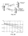
- the antenna array 1 can be constituted by way of example, antennas known as GSM / DCS1800 arranged on the the roof of a vehicle, ensuring that the distance between elements is at least equal to 0.5 times the longest wavelength ⁇ used in order to obtain fading states for each emission independent on each sensor. Geometric distribution matters little and the number of antennas employed may be variable, however the number 5 is a good balance between performance and complexity of treatment. Examples of antenna implantation are shown in Figures 5 and 6.
- functions of the device can be supplemented by a function of GPS positioning to correlate the scrambling assumptions with network planning and the location of the measurement, and a function of teleoperation and telemetry, in order to have autonomous equipment on the place of measurement.
- the identification of the base stations challenged by a interference phenomenon takes place according to steps 6 to 21 of the process represented in the flowchart of Figure 7.
- This process allows to perform for each selected channel on the one hand, the search for base stations using this channel as beacon frequency, with a decoding type 3 messages to obtain the identity of the CI cell and the code of its location LAC and secondly, search stations using this channel as the traffic frequency, as well as the search for the associated beacon frequency by identifying it thanks synchronism of bursts transmitted on beacon and traffic frequencies by the same base station.
- This identification takes place taking into account the specificities of the GSM system, namely that it provides for two types of channel frequencies associated with each base station, a frequency channel of beacon and traffic frequency channels.
- the beacon frequency channel (only one per station) allows the base station to broadcast to the mobiles served by the cell a certain number of signaling information not dedicated to a communication or to a mobile. It also serves as a frequency reference for mobile and is issued at a constant level even if it is not traffic information because a constant level of mobile devices to perform quick identification. It also carries specific bursts (SCH bursts) allowing synchronization time and the identification of reference sequences (TSC) that are used for signaling bursts.
- SCH bursts specific bursts
- TSC reference sequences
- Traffic frequency channels are all other channels Frequencies used, they mainly carry traffic bursts (burst TCH) and present energy only when a communication is conveyed on the TCH bursts.
- burst TCH traffic bursts
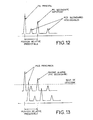
- step 8 a multichannel synchronization of SCH burst on a sequence of 64-bit long reference as shown in Figure 8. This sequence has sufficient autocorrelation performance that make it easy to identify reported interference situations by several synchronization peaks. These bursts are present on the time interval TNO of the multiframe 51 of the beacon frequency, as shown in Figure 9.
- the FCH bursts marked with the letter F are bursts unmodulated which correspond to a carrier and which allow mobile devices to perform rapid detection of beacon frequencies.
- the BCCH bursts marked with the letter B are signaling bursts general, to all mobiles carrying the signaling and which contain the identification information of the cells (CI) and localization (LAC).
- the PAGCCH bursts spotted by the letter P are mobile call bursts. These last two types of bursts are like the TCH bursts of traffic bursts that carry the voice.
- the process continues at step 10 of the flowchart of the Figure 7, performing a multi-channel demodulation of SCH bursts identified in FIG. 9 by the letter S, in order to extract the code identification of BSIC stations.
- the BSIC code contains two information. A first information indicates the PLMN number of the network and a second information indicates the reference sequence. TSC that will be used by the base station on the bursts of signaling. This second piece of information is coded the way represented in FIG. 10.
- the coding implements a cyclic code for the generation of a CRC error correcting code and a code convolutional to improve demodulation performance.
- the interest of decode the BSIC code is that it allows the identification of base stations in the presence. A consultation of a planning database allows then to isolate the stations presenting the same emissions of beacon frequency and the same BSIC code.
- a second type of information that identifies the stations in presence is the CI information which is the abbreviation of "Cell identity”.
- This information is transmitted by base stations on beacon frequency using BCCH bursts. These bursts aim to convey system signaling messages including the type 3 message which contains the identification information Cl and LAI, LAI being the abbreviation of "Location Area Identification” which makes it possible to identify a group of cells in which is broadcast a call.
- the type 3 message is cyclically transmitted on the Beacon frequency at a rate of two times per two second cycle. This gives the possibility to the device to store at least one second signal and thus have at least one recurrence of type 3 message.
- the CI and LAI information is coded according to the Figure 11. This coding consists in spreading the message over the 4 bursts BCCH of multiframe 51 from block interleaving resulting from a convolutive encoding of the type 3 message to which is attached an error correction CRC code.
- Steps 14 and 15 are preliminary steps that consist of first to perform at step 14 a multi-channel synchronization on the TCH bursts before performing their detection in step 15. Only 3 Types of waveform bursts shown in Figure 8 are used. They concern FCH bursts, SCH bursts and traffic bursts. All bursts BCCH, PAGCH, etc. are actually bursts with the same physical structure as the TCH bursts and which consist of a sequence of 26 framed symbols of two data areas of 58 useful symbols.
- synchronization step 14 is performed by successively performing a test of each of the possible sequences and providing the position of the bursts detected as well as the detected sequences.
- Steps 16 to 21 in Figure 7 are intended to identify the base station transmitting the disruptive traffic frequency.
- the method performs in step 16 a temporal marking of the arrival interfering traffic bursts, and position the system on another frequency in step 17. On this frequency, it will look at step 18, SCH bursts respecting a TDMA rhythm consistent with that indicated by the time stamping of step 16.
- Step 19 allows you to perform the detection: if it finds a SCH burst that respects the TDMA rhythm, then the process goes to step 20, otherwise it goes back to step 17 to change frequency.
- Step 20 makes it possible to perform the demodulation of the synchronous beacon frequency of the traffic frequency and provide among the signaling messages the list of traffic frequencies used by the cell that has this beacon frequency.
- Step 21 allows to compare this list to the frequency of interfering traffic. In case concordance, the interfering cell is found and the method provides its CI identification and its BSIC code, by decoding the SCH bursts of the beacon frequency.
- This algorithm takes into account the prediction that can be performed on the position of the secondary peaks and on their level.
- the processing starts in step 22 by detecting TCH bursts, followed in step 23 by sorting the detected bursts by sorting them into a list in descending order of their estimated signal to noise ratio SNIR.
- step 22 locating the position of the reference sequences is performed and the SNIR corresponding to each position is estimated.
- Step 24 makes it possible to initialize the filtering process by positioning a pointer N on the first position in the list.
- step 25 The purpose of step 25 is to select the current TSC, the SNIR current and current position of the selected item in the list by the pointer N.
- Step 26 makes it possible to position a second pointer K in the same position as the first pointer.
- Step 27 allows move the second pointer K to the next position in the list.
- Step 28 makes it possible to address an ambiguity table with as input the TSCs used by the elements of the list pointed by the two pointers N and K. This table determines the list of deviations ambiguity in time possible for the two selected TSCs, as well as for each ambiguity gap, the associated SNIR.
- TSC i the eight training sequences
- the positions ⁇ p for which the threshold has been exceeded at least once.
- the average value of the synchronization criterion is calculated when the threshold is exceeded, as well as the percentage of cases where the threshold has been exceeded.
- the results are stored in the ambiguity table, exploited by the sorting algorithm, which takes these values into account in order to decide that a sequence TSC i detected on a position p should not be retained since it corresponds in fact to a sequence TSC i transmitted on the position p + ⁇ p.
- Step 29 compares the measured difference for the two elements of the list with the list of possible time differences for ambiguity TSC. If a concordance exists the process continues in step 30, otherwise it goes to the execution of step 27 to position the second pointer K on the next item in the list.
- Step 30 is optional. She makes a comparison between the SNIRs of the ambiguity table and those detected. concordance exists, the process continues in step 31, if not it returns to step 27 to position the second pointer K on another item in the list.
- Step 31 eliminates the element pointed by K.
- Step 32 checks if there are any items in the list to go through the pointer K, if yes the process returns to step 27 to increment the pointer K. Otherwise it continues at step 33 to increment the N pointer
- Step 34 completes the process by checking if there are any remaining items in the list to increment the N pointer. If so, then the process returns to step 25. Otherwise the process is complete.
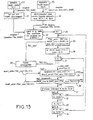
- This algorithm can, however, be optimized in the case of a traffic jamming on a beacon frequency.
- the positions of the traffic bursts on the beacon frequency are known from the positions of bursts SCH.
- the positions of the bursts TCH of a beacon frequency being perfectly known these, do not should not be filtered by the sort algorithm. This is what is represented on the flowchart in Figure 15, or the positions corresponding to these bursts are at the top of the list and are not questioned in the filtering.
- Treatment begins at step 35 by locating the bursts SCH, the determination of the BSIC (which provides the TSC sequence of the bursts BCCH), and the determination of SNIR signal-to-noise ratios correspondents. This is a list of M positions that were not questioned.
- steps 22 and 23 identical to those of Fig. 14, which provide another list.
- assistants in step 37 taking care to place the M elements previous ones at the top of the list, and eliminate redundancies.
- the filtering process can then start, as specified in figure 15. It is identical to that of figure 14, except at the stage 38 which does not allow to position the pointer K at the top of the list (only after the Mth item in the list).
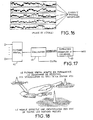
- FIG. 17 A device for carrying out the method is shown in FIG. 17.
- This device comprises a spatial filtering device 42 coupled to a message extraction and decoding device 43.
- the execution of the first step of the method consisting of to detect the presence of SCH bursts on a beacon channel or the presence of TCH bursts on a traffic channel can be implemented according to the synchronization technique described in the French patent application No. FR 2715488 filed in the name of the Applicant entitled "Method and device for a modem to synchronize on a digital data transmitter over the air in the presence of jammers. This technique allows a modem to synchronize using learning sequences inserted into the waveform.
- this technique makes it possible to detect the presence of a burst of SCH or TCH type on a sample p of signal as a function of the value of a multichannel synchronization criterion C (p) defined by the relation: with:
- the synchronization is placed at the moment of appearance of a sample (p) of signal when the value C (p) of the criterion is greater than a determined threshold value ⁇ .
- This SNIR is used during step 30 of the sorting algorithm of TCH bursts.
- the implementation of multi-channel synchronization therefore requires, for each position p tested, the computation of r and Xd (p), of R and XX (p) of the inverse of R and XX (p) and of the criterion r and Xd (p) R and -1 XX (p). r and Xd (p).
- the matrix R and XX (p) is calculated and inverted for all P positions, ie for the positions p 0 such that p modulo P is zero, in performing the correlation on N + P samples:
- the criterion C (p) is calculated using R and -1 XX (p 0 ), the calculation of r and Xd (p) remaining unchanged.
- the detected synchronization positions provide the starting information necessary for the demodulation.
- the demodulation is obtained according to two stages, a filtering stage by the device 42 and a single-channel equalization step by the 44.
- Spatial filtering makes it possible, on the one hand, to eliminate interference on the same or adjacent channel and on the other hand, to obtain a gain of diversity that is obtained by spreading enough sensors to each other to receive independent fading states.
- Spatial filtering can be implemented either by using a known method of spatial filtering on replica simple (FAS-R) that leads to separate the different multipath associated with a given emission, either by using a spatial filtering method filtered replication (FAS-RF) which allows for it to take into account all of these multipaths.
- FAS-RF spatial filtering method filtered replication
- Spatial filtering and equalization are implemented in the invention by exploiting the SCH training sequences for the demodulation of SCH bursts or TSC training sequences for the demodulation of BCCH bursts.
- the filtered overhead filtering method is described in the French patent application No. FR 2742619 filed in the name of the Applicant entitled: "Multi-sensor equalization process allowing multi-sensor reception in the presence of interference and multipath propagation, and receiver for its implementation "and for inventors MM. Institut PIPON, Pierre VILA and Didier PIREZ.
- FIG. 21 One embodiment of the equalizing device 44 is shown in FIG. 21.
- This includes a computing device 45 coupled to a replica 42 spatial filtering device via of a matched filter 46 and a channel estimation device 48.
- computing device 45 performs the one-dimensional equalization of the signals at the output of the spatial filtering for each of the detected sources.
- a signal processing processor 47 suitably programmed according to the known Viterbi algorithm coupled on the one hand, to the spatial filter 42 through the adapted filter 46 and on the other on the other hand, to a channel estimation device 48 through a calculation of the coefficients ⁇ 49 necessary for the execution of the algorithm of Viterbi.
- a calculation device for estimating the signal-to-noise ratio 50 is also coupled at the output of the computing device 49 and at the output of the channel estimation device 48.
- the processor 47 determines the transmitted symbol sequence that minimizes the probability of error of decision.
- One-dimensional equalization can also be performed by other types of algorithms, less complex numerically as the Viterbi algorithm, which are used for a single-sensor reception as the one known as "Algorithm" which is a simplified version of the Viterbi algorithm or even the DFE equalizer, although these EQs lead to slightly degraded results compared to those obtained with the algorithm from Viterbi. However, they can be used for applications or the available computing power is insufficient to implement this latest.
- (d n ) denotes the sequence of transmitted bits, taking values '0' or '1' and it is assumed that the data d n are differentially coded before being modulated.
- the modulation GMSK is a modulation to continuous phase that can express itself in an approximate way in the form linear modulation as described in the article by M. P.A. LAURENT, with the title: “Exact and approximate construction of digital phase modulation by superposition of amplitude modulated pulse (AMP) ", IEE Trans., Comm Flight 34 (1986) pp. 150-160.
- AMP amplitude modulated pulse
- the demodulation consists in determining the sequence (s n ) and then going up again following the transmitted bits (d n ).
- X (t) can also be written according to the symbols transmitted according to the relation: where Ts is the symbol period.
- the processor 47 determines the transmitted symbol sequence. It is programmed according to the Viterbi algorithm, a description of which can be found in the article by MJG PROAKIS, entitled "Adaptive Equalization for TDMA Digital Mobile Radio", IEEE Trans. On Vehicular Techn., vol 40, n ° 2, May 1991.
- This algorithm makes it possible, from a sequence of symbols (y n ) obtained at the output of the matched filter 46, to find the sequence (s k0 n ) of index k 0 which minimizes the probability of decision error on the transmitted sequence of symbols, or in an equivalent manner that maximizes the following criterion:
- the Viterbi algorithm works from the output signal y n of the matched filter 46 and the coefficients ⁇ n obtained at the output of the computing device 49.
- This calculation is performed by the computing device 48 which applies this result on an input of the device for calculating the signal-to-noise ratio 50.
- the factor 2n is due to the fact that the coefficients used by the Viterbi algorithm are calculated at the symbol rate).
- the signal-to-noise ratio at the output of the spatial filter 42 is equal to the coefficient ⁇ 0 .
- This noise is in first approximation only composed of background noise, since the interference formed by other emissions are rejected.
- the coefficient ⁇ 0 therefore constitutes an estimate of the signal-to-noise ratio at the output of the spatial filter.
- the first two phenomena can be taken into account by a calibration by injecting a known level signal at the input of receivers and comparing the estimated level in dBm at the actually injected.
Landscapes
- Engineering & Computer Science (AREA)
- Computer Networks & Wireless Communication (AREA)
- Signal Processing (AREA)
- Mobile Radio Communication Systems (AREA)
Claims (12)
- Verfahren zur Analyse der Interferenzen in einem zellularen Funkverkehrssystem, das Bakenfrequenzen und Verkehrsfrequenzen enthält, dadurch gekennzeichnet, dass es bei der Suche auf einer bestimmten Analysefrequenz und innerhalb einer Zelle nach dem Ursprung von Interferenzen, die von benachbarten Zellen verursacht werden, darin bestehteine Mehrkanalsynchronisation auf die Lernsequenzen der Bakenfrequenzen durchzuführen (8), um die Anzahl von Basisstationen zu bestimmen, die die Analysefrequenz als Bakenfrequenz nutzen,nach räumlicher Filterung die Kennungen der Bakenfrequenzen sendenden Basisstationen zu demodulieren (10), an denen eine Synchronisation vorgenommen wurde,eine Mehrkanalsynchronisation auf die Lernsequenzen der Verkehrsfrequenzen durchzuführen (14), um die Anzahl von Basisstationen zu bestimmen, die die Analysefrequenz als Verkehrsfrequenz nutzen.
- Verfahren nach Anspruch 1, dadurch gekennzeichnet, dass es zur Bestimmung der Kennungen der Basisstationen, die die Analysefrequenz als Verkehrsfrequenz nutzen, darin besteht, in allen Frequenzen des Netzes die Basisstationen zu suchen (22,..,36), von denen eine Bakenfrequenz mit der Verkehrsfrequenz synchron ist, sie nach räumlicher Filterung zu demodulieren, um ihre Kennungen zu erhalten, nämlich Bakenfrequenz und Identität der Basisstation, und diejenige beizubehalten, die die Analysefrequenz in der Liste der demodulierten Verkehrsfrequenzen enthält.
- Verfahren nach einem der Ansprüche 1 und 2, dadurch gekennzeichnet, dass es zur Durchführung der Mehrkanalsynchronisation auf die den Baken- oder Verkehrsfrequenzen zugeordneten Lernfrequenzen mit oder ohne Vorhandensein von Störsignalen darin besteht, die Korrelationsmatrix R andXX von in einer Einheit von N Sensoren empfangenen Signalen zu schätzen, die inverse Korrelationsmatrix R and-1 XX zu berechnen, Interkorrelationsvektoren r andXd zwischen den in der Gesamtheit der N Sensoren empfangenen Signalen X(k) und einem bekannten Lernsignal d(n) zu berechnen, ein Synchronisations-Multiplikationskriterium zu berechnen, indem das Skalarprodukt zwischen dem Interkorrelationsvektor r andXd und einem Vektor gebildet wird, der durch das Produkt der inversen Korrelationsmatrix R and-1 XX und des transponierten konjugierten Interkorrelationsvektor r and+ Xd erhalten wird, und den Wert des erhaltenen Kriteriums mit einem bestimmten Schwellenwert η zu vergleichen, um die Synchronisation auf die Tastprobe (P) des Signals zu bringen, für das der Wert des Kriteriums den Schwellenwert η übersteigt.
- Verfahren nach Anspruch 3, dadurch gekennzeichnet, dass die Lernsequenz d(n) der Lernsequenz der Signale SCH und TCH der Funkverkehrssysteme GSM und DCS1800 entspricht.
- Verfahren nach einem der Ansprüche 1 bis 4, dadurch gekennzeichnet, dass auf einer Bakenfrequenz die Demodulation der Signalisationsnachrichten, die insbesondere die zugehörigen Verkehrsfrequenzen und die Identität der Basisstation angeben, durch räumliches Filtern erhalten wird, indem die Lernsequenz der Bakenfrequenz ausgewertet wird, um das Empfangsdiagramm zu verändern und die verschiedenen empfangenen Signale zu trennen, wobei Empfangslöcher in Richtung der Störsignale gebildet werden, die von anderen Basisstationen und Störsendern außerhalb des Netzes erzeugt werden.
- Verfahren nach Anspruch 5, dadurch gekennzeichnet, dass es darin besteht, ein Verfahren der räumlichen Filterung auf Replik einzusetzen, indem der Weg mit dem stärksten Leistungspegel verwendet wird, der ausgehend von der Mehrkanalsynchronisation für die Anpassung des räumlichen Filters bestimmt wird.
- Verfahren nach Anspruch 5, dadurch gekennzeichnet, dass es darin besteht, ein Verfahren der räumlichen Filterung auf gefilterter Replik zu verwenden, das es ermöglicht, die Gesamtheit der Nutzwege zur Anpassung des räumlichen Filters einzusetzen.
- Verfahren nach Anspruch 7, dadurch gekennzeichnet, dass es darin besteht, eine eindimensionale Egalisierung der durch räumliche Filterung erhaltenen Signale durchzuführen.
- Vorrichtung zur Analyse der Interferenzen in einem zellularen Funkverkehrssystem, das Bakenfrequenzen und Verkehrsfrequenzen enthält, dadurch gekennzeichnet, dass sie ein Antennennetz (1), das mit einem Mehrkanalempfänger (2) für den synchronen Empfang von Signalen gekoppelt ist, die von jeder der Antennen empfangen werden, und eine digitale Einrichtung (3) aufweist, die mit dem Mehrkanalempfänger (2) gekoppelt ist, und in der Lage ist:eine Mehrkanalsynchronisation auf die Bakenfrequenz-Lernsequenz durchzuführen (8), um die Anzahl von Basisstationen zu bestimmen, die die Analysefrequenz als Bakenfrequenz verwenden,nach räumlicher Filterung die Kennungen der Basisstationen zu demodulieren (10), die Bakenfrequenzen senden, auf die eine Synchronisation vorgenommen wurde,eine Mehrkanalsynchronisation auf die Lernsequenzen der Verkehrsfrequenzen durchzuführen (14), um die Anzahl von Basisstationen zu bestimmen, die die Analysefrequenz als Verkehrsfrequenz verwenden.
- Vorrichtung nach Anspruch 9, dadurch gekennzeichnet, dass die Einrichtung zur digitalen Verarbeitung (3) in der Lage ist, in einem GSM DCS1800-Netz in den Kanälen vom Typ Bake das Identifikationswort BSIC der Zellen zu bestimmen, das nach der Demodulation der Bursts SCH erhalten wurde, sowie die Identität CI und den Lokalisationscode LAC jeder Zelle zu bestimmen, die nach der Demodulation der Bursts BCCH erhalten wurden.
- Vorrichtung nach einem der Ansprüche 9 und 10, dadurch gekennzeichnet, dass die Antennen des Antennennetzes (1) einen Abstand zueinander aufweisen, der größer ist als 0,5 mal die größte Wellenlänge der im Funkverkehrssystem verwendeten Frequenzen.
- Vorrichtung nach einem der Ansprüche 9 bis 11, dadurch gekennzeichnet, dass der Mehrkanalempfänger (2) eine Vorrichtung zur Entnahme von Nachrichten und zur Decodierung (43) aufweist, die mit einer Vorrichtung zur räumlichen Filterung (42) über eine eindimensionale Egalisierungsvorrichtung (44) gekoppelt ist, die einen gemäß dem Viterbi-Algorithmus programmierten Prozessor aufweist.
Applications Claiming Priority (3)
| Application Number | Priority Date | Filing Date | Title |
|---|---|---|---|
| FR9708954A FR2766320B1 (fr) | 1997-07-15 | 1997-07-15 | Procede et dispositif d'analyse des interferences dans un systeme de radiocommunication cellulaire |
| FR9708954 | 1997-07-15 | ||
| PCT/FR1998/001511 WO1999004588A1 (fr) | 1997-07-15 | 1998-07-10 | Procede et dispositif d'analyse des interferences dans un systeme de radiocommunication cellulaire |
Publications (2)
| Publication Number | Publication Date |
|---|---|
| EP0931429A1 EP0931429A1 (de) | 1999-07-28 |
| EP0931429B1 true EP0931429B1 (de) | 2005-09-14 |
Family
ID=9509224
Family Applications (1)
| Application Number | Title | Priority Date | Filing Date |
|---|---|---|---|
| EP98937617A Expired - Lifetime EP0931429B1 (de) | 1997-07-15 | 1998-07-10 | Verfahren und vorrichtung zur interferenzanalyse in einem zellularen mobilkommunikationssystem |
Country Status (5)
| Country | Link |
|---|---|
| US (1) | US6349207B1 (de) |
| EP (1) | EP0931429B1 (de) |
| DE (1) | DE69831556T2 (de) |
| FR (1) | FR2766320B1 (de) |
| WO (1) | WO1999004588A1 (de) |
Families Citing this family (35)
| Publication number | Priority date | Publication date | Assignee | Title |
|---|---|---|---|---|
| DE19851550A1 (de) * | 1998-11-09 | 2000-05-11 | Rohde & Schwarz | Verfahren zum Messen und Zuordnen von Störsignalen in zellularen Funknetzen |
| US6498936B1 (en) * | 1999-01-22 | 2002-12-24 | Ericsson Inc. | Methods and systems for coding of broadcast messages |
| FR2790098B1 (fr) * | 1999-02-23 | 2001-05-11 | Thomson Csf | Procede de localisation de radios mobiles terrestres a partir d'un aeronef |
| FR2799082B1 (fr) * | 1999-09-28 | 2001-11-02 | Thomson Multimedia Sa | Procede d'association d'un appareil dans un reseau de communication |
| US6442384B1 (en) * | 1999-10-22 | 2002-08-27 | Ericsson Inc. | System and method for identification of uplink/downlink interference sources |
| FR2805614B1 (fr) | 2000-02-25 | 2003-08-22 | Thomson Csf | Procede de localisation de sources radioelectriques au moyen d'un radiogoniometre haute resolution deux voies |
| US6754487B1 (en) | 2000-02-28 | 2004-06-22 | Telecom Network Optimization, Inc. | Radio network test analysis system |
| US6950665B2 (en) | 2000-02-29 | 2005-09-27 | Pctel, Inc. | Methodology and system for generating a three-dimensional model of interference in a cellular wireless communication network |
| FR2806499B1 (fr) * | 2000-03-20 | 2003-10-10 | Thomson Csf | Procede d'estimation d'une matrice de correlation de signaux interferents recus par un reseau de capteurs |
| FR2807267B1 (fr) * | 2000-03-28 | 2002-12-06 | Schlumberger Systems & Service | Reseau de radiotelephonie mobile etendu et publiphone pour la mise en oeuvre d'un tel reseau |
| USRE43871E1 (en) | 2000-08-15 | 2012-12-25 | Pctel, Inc. | System and method for identifying co-channel interference in a radio network |
| GB2367721B (en) * | 2000-10-06 | 2004-03-03 | Motorola Inc | Network management system and method of management control in a communication system |
| FR2819357B1 (fr) * | 2001-01-09 | 2016-02-12 | Thomson Csf | Procede et recepteur autodidacte pour determiner les parametres spatio-temporels d'un canal de propagation |
| FR2820580B1 (fr) | 2001-02-02 | 2004-06-04 | Thomson Csf | Procede pour estimer les parametres d'un canal de propagation |
| FR2821502A1 (fr) * | 2001-02-27 | 2002-08-30 | Thomson Csf | Procede et dispositif d'estimation d'un canal de propagation a partir de ses statistiques |
| FR2824146B1 (fr) * | 2001-04-27 | 2006-02-24 | Thomson Csf | Systeme et procede de localisation de radiomobiles en dehors de la couverture d'un reseau cellulaire |
| FR2824145B1 (fr) | 2001-04-27 | 2005-04-15 | Thomson Csf | Procede et dispositif d'estimation spatio-temporelle d'un ou plusieurs emetteurs |
| FR2829241B1 (fr) | 2001-09-05 | 2006-07-21 | Thales Sa | Procede et dispositif de radiogoniometrie cooperative en transmission |
| FR2829325B1 (fr) * | 2001-09-05 | 2005-06-17 | Thales Sa | Procede et dispositif de detection de sources dans un systeme de communication |
| US7180881B2 (en) * | 2001-09-28 | 2007-02-20 | Interdigital Technology Corporation | Burst detector |
| ATE429137T1 (de) | 2002-01-25 | 2009-05-15 | Ericsson Telefon Ab L M | Verfahren zur störungsquellenidentifikation |
| FI116179B (fi) * | 2002-03-13 | 2005-09-30 | Nokia Corp | Menetelmä ja järjestelmä etenemisviiveen määrittämiseksi sekä elektroniikkalaite |
| US7013113B2 (en) * | 2002-07-25 | 2006-03-14 | Pctel Maryland, Inc. | Method and apparatus for co-channel interference measurements and interference component separation based on statistical signal processing in drive-test area |
| US6832074B2 (en) * | 2002-11-04 | 2004-12-14 | Telcordia Technologies, Inc. | Method and system for real time cellular network configuration |
| FR2854290B1 (fr) * | 2003-04-25 | 2005-08-26 | Thales Sa | Procede de demodulation de signaux de type ofdm en presence de signaux brouilleurs co-canaux forts |
| GB0327041D0 (en) * | 2003-11-21 | 2003-12-24 | Roke Manor Research | Apparatus and methods |
| US7236746B2 (en) * | 2004-02-04 | 2007-06-26 | Pctel, Inc. | Method and apparatus for measurement and identification of co-channel interfering transmitters |
| FR2869189B1 (fr) | 2004-04-16 | 2006-06-02 | Thales Sa | Procede de controle et d'analyse des communications dans un reseau de telephonie |
| ATE414350T1 (de) * | 2004-06-18 | 2008-11-15 | Ericsson Telefon Ab L M | Cosequenz-störungsdetektion und -behandlung |
| FR2891627B1 (fr) * | 2005-10-03 | 2010-01-08 | Thales Sa | Dispositif compact de radio surveillance. |
| US7593738B2 (en) * | 2005-12-29 | 2009-09-22 | Trueposition, Inc. | GPS synchronization for wireless communications stations |
| US7639985B2 (en) * | 2006-03-02 | 2009-12-29 | Pc-Tel, Inc. | Use of SCH bursts for co-channel interference measurements |
| DE602008004571D1 (de) * | 2007-10-08 | 2011-02-24 | Ericsson Telefon Ab L M | Verfahren und anordnung für ereignisgetriggertes adaptives zellendetektionsaktivitätsniveau beim diskontinuierlichen empfang |
| US9357046B2 (en) * | 2013-03-10 | 2016-05-31 | Qualcomm Incorporated | Detecting electromagnetic energy for alarm or log using mobile phone devices |
| TWI769012B (zh) * | 2021-07-12 | 2022-06-21 | 瑞昱半導體股份有限公司 | 多點網路系統與網路裝置 |
Family Cites Families (6)
| Publication number | Priority date | Publication date | Assignee | Title |
|---|---|---|---|---|
| FR2715488B1 (fr) | 1994-01-21 | 1996-03-22 | Thomson Csf | Procédé et dispositif permettant à un modem de se synchroniser sur un transmetteur de données numériques par voie hertzienne en présence de brouilleurs. |
| FR2732490B1 (fr) | 1995-03-28 | 1997-04-25 | Thomson Csf | Procede de reception multicapteur d'une station de base d'un reseau de communication echangeant des donnees avec des mobiles, et dispositif pour sa mise en oeuvre |
| US5848105A (en) * | 1996-10-10 | 1998-12-08 | Gardner; William A. | GMSK signal processors for improved communications capacity and quality |
| US5930243A (en) * | 1996-10-11 | 1999-07-27 | Arraycomm, Inc. | Method and apparatus for estimating parameters of a communication system using antenna arrays and spatial processing |
| US5870430A (en) | 1996-12-26 | 1999-02-09 | Thomson-Csf | Process for multi-sensor equalisation in a radio receiver in the presence of interference and multiple propagation paths |
| US5937014A (en) * | 1997-03-27 | 1999-08-10 | Telefonaktiebolaget Lm Ericsson | Self-synchronizing equalization techniques and systems |
-
1997
- 1997-07-15 FR FR9708954A patent/FR2766320B1/fr not_active Expired - Fee Related
-
1998
- 1998-07-10 WO PCT/FR1998/001511 patent/WO1999004588A1/fr active IP Right Grant
- 1998-07-10 US US09/147,822 patent/US6349207B1/en not_active Expired - Lifetime
- 1998-07-10 DE DE69831556T patent/DE69831556T2/de not_active Expired - Lifetime
- 1998-07-10 EP EP98937617A patent/EP0931429B1/de not_active Expired - Lifetime
Also Published As
| Publication number | Publication date |
|---|---|
| US6349207B1 (en) | 2002-02-19 |
| DE69831556D1 (de) | 2005-10-20 |
| WO1999004588A1 (fr) | 1999-01-28 |
| FR2766320B1 (fr) | 1999-10-15 |
| DE69831556T2 (de) | 2006-06-14 |
| EP0931429A1 (de) | 1999-07-28 |
| FR2766320A1 (fr) | 1999-01-22 |
Similar Documents
| Publication | Publication Date | Title |
|---|---|---|
| EP0931429B1 (de) | Verfahren und vorrichtung zur interferenzanalyse in einem zellularen mobilkommunikationssystem | |
| EP0095959B1 (de) | Funkverbindungssystem nach dem Frequenzsprungverfahren | |
| CA2172672C (fr) | Procede de reception multicapteur d'une station de base fixe d'un reseau de communication echangeant des donnees avec des mobiles, et dispositif pour sa mise en oeuvre | |
| EP1998469B1 (de) | Opportunistisches Funkendgerät und entsprechendes Verfahren zur Bandsuche | |
| FR2686202A1 (fr) | Procede d'affectation dynamique de voies dans un systeme de telecommunications et systeme radiotelephonique utilisant un tel procede. | |
| EP0903049B1 (de) | Verfahren zur einleitung des weiterreichens von gesprächen in einem zellularfunksystem | |
| EP2387189B1 (de) | Verfahren zur Demodulation von Signalen eines Mehrfachzugriffsystems, die untereinander eine Kollision verursachen können, und Instrumente zu deren Umsetzung | |
| CA2382415C (fr) | Systeme et procede de localisation de radiomobiles en dehors de la couverture d'un reseau cellulaire | |
| EP0991952B1 (de) | Verfahren zur funkpeilung und zusammenwirkendes übertragungsgerät | |
| FR2956745A1 (fr) | Procede de recouvrement d'un signal parmi un ensemble de signaux collectes par satellite. | |
| EP1260071B1 (de) | Verfahren und vorrichtung für kanalschäztung | |
| WO2003084256A2 (fr) | Procede de mesure pendant une procedure de transfert dans un systeme de communications mobiles | |
| EP1179282A1 (de) | Verfahren und vorrichtung zur schätzung einer signalcharakteristik | |
| FR2841407A1 (fr) | Procede d'optimisation de la recherche de cellules dans un reseau de telecommunication mobile | |
| EP0817397B1 (de) | Verfahren zur Schaltung eines Kanals von einem ersten auf einen zweiten Übertragungsweg | |
| FR2824207A1 (fr) | Procede et dispositif de localisation d'un mobile au sein d'un reseau de communication | |
| EP0689302A1 (de) | Kontrollsignal für Empfänger, Gerät für Synchronisation und Equalisation, Synchronisationsverfahren und Empfänger dafür | |
| EP1714511B1 (de) | Verfahren zur optimierung der planung in einem cdma-kommunikationssystem | |
| EP2661637B1 (de) | Orientiertes protokollverfahren zur verarbeitung von stationären signalen, teilweise stationären signalen oder zyklostationären signalen | |
| EP1879420B1 (de) | Verfahren und Vorrichtung zur Suche von gerade laufenden Anrufen mittels einer Empfangsmobilstation eines Systems für direkten Mobilfunk mit Zeitmultiplexzugriff | |
| EP2308192B1 (de) | Verfahren zum erzeugen eines szenarios von elektromagnetischem rauschen | |
| FR2902195A1 (fr) | Procede de determination de l'instant d'arrivee d'un signal radioelectrique non impulsionnel et systeme de localisation geographique d'emetteurs de signaux radioelectriques non impulsionnels | |
| FR2797139A1 (fr) | Dispositif et procede d'emission d'un signal trompeur destine a un telephone mobile |
Legal Events
| Date | Code | Title | Description |
|---|---|---|---|
| PUAI | Public reference made under article 153(3) epc to a published international application that has entered the european phase |
Free format text: ORIGINAL CODE: 0009012 |
|
| 17P | Request for examination filed |
Effective date: 19990322 |
|
| AK | Designated contracting states |
Kind code of ref document: A1 Designated state(s): DE FI FR GB SE |
|
| RAP1 | Party data changed (applicant data changed or rights of an application transferred) |
Owner name: THALES |
|
| 17Q | First examination report despatched |
Effective date: 20031106 |
|
| GRAP | Despatch of communication of intention to grant a patent |
Free format text: ORIGINAL CODE: EPIDOSNIGR1 |
|
| GRAS | Grant fee paid |
Free format text: ORIGINAL CODE: EPIDOSNIGR3 |
|
| GRAA | (expected) grant |
Free format text: ORIGINAL CODE: 0009210 |
|
| AK | Designated contracting states |
Kind code of ref document: B1 Designated state(s): DE FI FR GB SE |
|
| PG25 | Lapsed in a contracting state [announced via postgrant information from national office to epo] |
Ref country code: FI Free format text: LAPSE BECAUSE OF FAILURE TO SUBMIT A TRANSLATION OF THE DESCRIPTION OR TO PAY THE FEE WITHIN THE PRESCRIBED TIME-LIMIT Effective date: 20050914 |
|
| REG | Reference to a national code |
Ref country code: GB Ref legal event code: FG4D Free format text: NOT ENGLISH |
|
| REF | Corresponds to: |
Ref document number: 69831556 Country of ref document: DE Date of ref document: 20051020 Kind code of ref document: P |
|
| GBT | Gb: translation of ep patent filed (gb section 77(6)(a)/1977) |
Effective date: 20051003 |
|
| PG25 | Lapsed in a contracting state [announced via postgrant information from national office to epo] |
Ref country code: SE Free format text: LAPSE BECAUSE OF FAILURE TO SUBMIT A TRANSLATION OF THE DESCRIPTION OR TO PAY THE FEE WITHIN THE PRESCRIBED TIME-LIMIT Effective date: 20051214 |
|
| PLBE | No opposition filed within time limit |
Free format text: ORIGINAL CODE: 0009261 |
|
| STAA | Information on the status of an ep patent application or granted ep patent |
Free format text: STATUS: NO OPPOSITION FILED WITHIN TIME LIMIT |
|
| 26N | No opposition filed |
Effective date: 20060615 |
|
| PGFP | Annual fee paid to national office [announced via postgrant information from national office to epo] |
Ref country code: DE Payment date: 20150707 Year of fee payment: 18 Ref country code: GB Payment date: 20150708 Year of fee payment: 18 |
|
| REG | Reference to a national code |
Ref country code: FR Ref legal event code: PLFP Year of fee payment: 19 |
|
| REG | Reference to a national code |
Ref country code: DE Ref legal event code: R119 Ref document number: 69831556 Country of ref document: DE |
|
| GBPC | Gb: european patent ceased through non-payment of renewal fee |
Effective date: 20160710 |
|
| PG25 | Lapsed in a contracting state [announced via postgrant information from national office to epo] |
Ref country code: DE Free format text: LAPSE BECAUSE OF NON-PAYMENT OF DUE FEES Effective date: 20170201 |
|
| PG25 | Lapsed in a contracting state [announced via postgrant information from national office to epo] |
Ref country code: GB Free format text: LAPSE BECAUSE OF NON-PAYMENT OF DUE FEES Effective date: 20160710 |
|
| REG | Reference to a national code |
Ref country code: FR Ref legal event code: PLFP Year of fee payment: 20 |
|
| PGFP | Annual fee paid to national office [announced via postgrant information from national office to epo] |
Ref country code: FR Payment date: 20170628 Year of fee payment: 20 |