EP0817397B1 - Method for switching a channel from a first to a second propagation path - Google Patents
Method for switching a channel from a first to a second propagation path Download PDFInfo
- Publication number
- EP0817397B1 EP0817397B1 EP97401515A EP97401515A EP0817397B1 EP 0817397 B1 EP0817397 B1 EP 0817397B1 EP 97401515 A EP97401515 A EP 97401515A EP 97401515 A EP97401515 A EP 97401515A EP 0817397 B1 EP0817397 B1 EP 0817397B1
- Authority
- EP
- European Patent Office
- Prior art keywords
- channel
- station
- communication
- following
- current
- Prior art date
- Legal status (The legal status is an assumption and is not a legal conclusion. Google has not performed a legal analysis and makes no representation as to the accuracy of the status listed.)
- Expired - Lifetime
Links
Images




Classifications
-
- H—ELECTRICITY
- H04—ELECTRIC COMMUNICATION TECHNIQUE
- H04B—TRANSMISSION
- H04B7/00—Radio transmission systems, i.e. using radiation field
- H04B7/14—Relay systems
- H04B7/15—Active relay systems
- H04B7/185—Space-based or airborne stations; Stations for satellite systems
- H04B7/1853—Satellite systems for providing telephony service to a mobile station, i.e. mobile satellite service
- H04B7/18539—Arrangements for managing radio, resources, i.e. for establishing or releasing a connection
- H04B7/18541—Arrangements for managing radio, resources, i.e. for establishing or releasing a connection for handover of resources
-
- H—ELECTRICITY
- H04—ELECTRIC COMMUNICATION TECHNIQUE
- H04B—TRANSMISSION
- H04B1/00—Details of transmission systems, not covered by a single one of groups H04B3/00 - H04B13/00; Details of transmission systems not characterised by the medium used for transmission
- H04B1/74—Details of transmission systems, not covered by a single one of groups H04B3/00 - H04B13/00; Details of transmission systems not characterised by the medium used for transmission for increasing reliability, e.g. using redundant or spare channels or apparatus
-
- H—ELECTRICITY
- H04—ELECTRIC COMMUNICATION TECHNIQUE
- H04L—TRANSMISSION OF DIGITAL INFORMATION, e.g. TELEGRAPHIC COMMUNICATION
- H04L1/00—Arrangements for detecting or preventing errors in the information received
- H04L1/22—Arrangements for detecting or preventing errors in the information received using redundant apparatus to increase reliability
Definitions
- the present invention generally relates to a method of switching, from a first propagation path to a second propagation path, a channel established between a first station and a second station.
- the invention applies, for example, to a satellite telecommunications network with mobiles operating in said switched diversity mode, according to which a communication established between a first station, for example a base station, and a second station, for example a mobile terminal, can be transmitted according to one of the two propagation paths respectively via two separate satellites.
- the invention can also be applied to a terrestrial radio network.
- a satellite telecommunications network embodying the invention comprises, on the one hand, switching and control units of base stations 2 connected via PCM links to the RTC Switched Telephone Network, and, on the other hand, multiple access base stations 3 connected in cluster to said units.
- the units 2 are responsible for routing communications from and to the mobile terminals 6 in a given geographical area, and for controlling one or more base stations 3.
- the base stations 3 provide in particular the transmission / radio reception of communications to / from mobile terminals 6.
- a communication, or channel, established with a mobile terminal 6 is selectively conveyed along one of at least two propagation paths 4A and 5A.
- the selection of one of these propagation paths results from a minimization of the transmitted satellite power for the communication considered.
- the communication established with the mobile terminal 6 is switched to that of the two propagation paths, 4A or 5A, respectively associated with the two satellites 4 and 5, which offers a minimum transmitted satellite power for a given transmission quality.
- the two propagation paths define between them, in view of the terminal, a difference in time, equal to the time difference between respective reception instants of data transmitted in synchronism along the two propagation paths 4A and 5A. Accordingly, this propagation path switching procedure must be associated with a terminal synchronization procedure.
- GSM Global System for Mobile Communications
- the next base station measures, in response to the receipt of this access message, a propagation delay between itself and the mobile terminal, and transmits to the terminal information relating to a time advance that the terminal must to apply to its clock with respect to what it believes to be the clock of the next station, so that the communication data transmitted by the terminal is received by the next base station synchronized temporally in a time interval of a frame received by the latter taking into account the distance between the following base station and terminal.
- the document EP 0 504 122 describes a cell change assisted by neighboring cells in a cellular communication system.
- this solution of the prior art proves to be inefficient. Indeed, in such a network, the small power margin allocated to each communication, in order to guarantee a minimum communication quality, leads to a rapid degradation of the communication in the presence for example of an obstacle. This rapid character of channel degradation also applies to control channels. This can then lead to an impossibility of reception by the terminal of a request message for switching a channel from a first propagation path to a second propagation path, and consequently to a loss of communication.
- the aim of the invention is to remedy this drawback by providing a particularly advantageous propagation path switching method, for example in the context of a satellite network.
- the method comprises a step of calculating in the second station a total time difference between the current channel and the following channel as a function of a part, (a) - of a time difference between two respective reception instants of control packets transmitted by the first station respectively according to the two propagation paths and, on the other hand, (b) - of a time advance which is a function of the distance between said second station and said first station.
- a first station for carrying out the method of the invention comprises means for allocating transmission and reception means to the current channel, and is characterized in that it comprises means for reserving transmission means and receiving at the next channel.
- a second station for implementing the method is characterized in that it comprises means for detecting a fault of reception of information in the current channel, and means for switching, in transmission and reception, said communication towards said channel next in response to a detection, by said means for detecting, of a reception error of information in said current channel.
- a base station 3 embodying the invention comprises a central unit 39, two transmission chains 36 and 36 ', two reception channels 38 and 38'. An output of the transmission channel 36 and an input of the reception channel 38 are coupled to a first antenna 37a pointing to the satellite 4. An output of the transmission channel 36 'and an input of the reception channel 38 are coupled to a second antenna 37b pointing to the satellite 5.
- the central unit 39 in addition to an interface function with the base station switching and control unit 2, provides channel routing, time advance calculation and channel switching functions between propagation paths 4A and 5A.
- This central unit is connected to the transmission channel 36 through a transmission bus B1, to the transmission channel 36 'through a transmission bus B1', to the reception channel 38 through a reception bus B2 and to the transmission channel receiving 38 'through a B2' receiving bus.
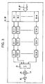
- each transmission channel 36, 36 comprises M transmission queues 30-1 to 30 -M, respective outputs of which are applied to inputs of M interleaving and coding units 31-1 to 31- Mr. Respective outputs of these M interleaving and coding units 31-1 to 31-M are applied to inputs of M QPSK modulation units 32-1 to 32-M. Respective outputs of these M QPSK modulation units 32-1 to 32-M are applied to respective inputs of M PN / Hadamard modulation units 33-1 to 33-M.
- the purpose of this encoder is to implement a coding that provides a guarantee of the quality of the link.
- Such a coding circuit is well known to those skilled in the art.
- the baseband data packets from a 30-m queue are encoded and then interleaved by the 31-m unit.
- the resulting interlaced signal is modulated in QPSK (Quadrature Phase Shift Keying) by the 32-m unit.
- QPSK Quadratture Phase Shift Keying
- the operation of the network is such that all the signals transmitted inside a cell (terrestrial network) or a beam (satellite network) use the same PN sequence (Pseudo-Noise) which is different from a PN sequence used by a neighbor cell or beam.
- a signal to a particular station, such as terminal is further encoded by a particular one of a plurality of orthogonal sequences.
- PN sequences consist of identical pseudo-random sequences that are temporally shifted between them for separate cells.
- Orthogonal sequences are for example Walsh functions, also known as "Hadamard sequences”.
- a Hadamard Hm sequence, m between 1 and M, is a respective one of the M lines of the Hadamard matrix.
- a Hadamard matrix of rank M thus contains M sequences, each having a length of M bits.
- Hadamard sequences of order M have the property that over an interval of M symbols, the correlation between the different sequences is zero, it being understood that these different sequences are temporally aligned. it results from the fact that each sequence differs from any other sequence for half of the bits that compose it.
- the two QPSK quadrature modulated signal components are both multiplied by a rank m H-Hadamard sequence and a PN sequence associated with the beam. F4, F5, to produce two quadrature signals modulated by code.
- the different quadrature signals from the different code modulation units 33-1 to 33-M are added by means of the adder 34.
- the multiplier 35 By means of the multiplier 35, the resulting addition signal is modulated by a transmission carrier. P before being amplified by the amplifier 35 'to be transmitted through the antenna 37a, 37b.
- This addition signal, or composite signal, transmitted through the antenna 37a, 37b is as shown in FIG. figure 5 . It uses, for example, an elementary frame pattern at four time intervals itl-it4 which repeats at the frame rate.
- a TCH communication channel established in the network described herein is defined by a time interval itj, j between 1 and 4, a Hadamard Hm sequence, and a PN code.
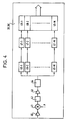
- each reception channel 38, 38 comprises an RF amplifier 40, a multiplier 41, a filter 42, an IF amplifier 43, an analog / digital converter 44, an output of which applies to respective inputs of the M demodulation units by code 45-1 to 45-M.
- M decoding and deinterleaving units 47-1 to 47-M receive on respective inputs the outputs of the M code demodulation units 45-1 to 45-M, and M queues 48-1 to 48-M receive in entrance the outputs respective M decoding and deinterleaving units 47-1 to 47-M.
- the base station allocates to the terminal a SACCH channel in which is conveyed time advance information that said terminal must give to its clock with respect to what it believes to be the clock of the base station, of so that the data subsequently transmitted by the terminal coincide with a given time interval of the frame.
- Time advance information will in our realization have a much higher accuracy than the GSM, to account for the modulation CDMA. A number of bits higher than those defined for this purpose in the GSM will therefore be used in the SACCH.
- the base station 3 therefore receives the different channels over perfectly synchronized time intervals, and modulated by Hadamard sequences, as shown in FIG. figure 5 illustrating M frame signals relating to a beam or a cell.
- these different signals are successively amplified RF by the amplifier 40, demodulated in the multiplier 41 by a demodulation carrier P produced by a generator (not shown), filtered bandpass by the filter 42, amplified IF 43, and undergo an analog / digital conversion 44.
- the composite signal from the analog / digital converter 44 is applied to the respective inputs of the M demodulation units by code 33-1 to 33- Mr.
- Each 45-m code demodulation unit, m between 1 and M comprises in cascade a QPSK / PN correlator and a fast Hadamard transform.
- a signal from a code demodulation unit is applied to a respective one of the 47-m decoding and deinterleaving units.
- the baseband signal from each 47-m decoding and deinterleaving unit is applied in a respective queue 48-1 to be read and routed by the CPU 39 to a switching unit and to base station control 2.
- each terminal operates in a temporal duplexing mode.
- a reception window corresponding to a time slot it1 to it4, and a transmission window separated temporally from the reception window, these two windows occupying together less than one frame duration T.
- the two satellites 4 and 5 define two coverage areas, or beams, respectively F4 and F5 defined by two different PN codes.
- the transmit and receive channels 36 and 36 are associated with the coverage area F4 while the transmit and receive channels 36 'and 38' are associated with the coverage area F5.
- a given terminal 6 is in both the F4 coverage area of the satellite 4 and in the F5 coverage area of the satellite 5.
- Each transmission channel 36 and 36 'in the base station 3 transmits continuously, at the frame rate, in a given time interval, here it1, of one of the M frame signals associated with a respective Hadamard sequence, here H1, a control channel said BCCH general information broadcast.
- the terminal, or second station, 6 comprises two code demodulation units 60 and 61, a code modulation unit 63 and a central unit 62.
- the two code demodulation units 60 and 61 receive through the antenna of the terminal 6, the composite signals respectively transmitted by the two transmission channels 36 and 36 'in the base station 3 ( FIG.7 , ET1).
- the demodulation unit 60 acquires the synchronization of PN and Hadamard codes relative to the frame signal carrying the BCCH channel transmitted by the transmission channel 36 of the base station 3.
- the demodulation unit 61 acquires the synchronization of PN and Hadamard codes relating to the frame signal carrying the BCCH channel transmitted by the transmission channel 36 'of the base station 3.
- At the output of these two code demodulation units 60 and 61, respectively, are produced the two baseband BCCH channel signals received via the satellites 4 and 5.
- BCCH channel signals are applied to the central unit 62.
- the latter periodically measures a value representative of a signal-to-noise ratio, for example a power level or a bit error rate, for each of these two BCCH channel signals respectively received according to the two propagation paths 4A and 5A ( FIG.7 , ET3).
- a signal-to-noise ratio for example a power level or a bit error rate
- the central unit 62 measures a time difference ⁇ t between these two BCCH channels, which are transmitted in synchronism along the two propagation paths 4A and 5A, respectively by the transmission channels 36 and 36 'in the transmission station. base 3 ( FIG.7 , ET2).
- this time difference difference ⁇ t can take a longer than a frame duration, it is expected that a BCCH channel vehicle, as is provided for other reasons in the GSM Recommendations, a frame rank information.
- the central unit 62 measures a time difference ⁇ t between the two BCCH channels by adding an apparent time difference and a time difference equal to the difference of the frame ranks in the two BCCH channels multiplied by the duration of frame T.
- the terminal For the establishment of a communication, whether outgoing or incoming, the terminal transmits in a so-called RACH channel, an access request message ( FIG.7 , ET5) through the code modulation unit 63. This message is issued immediately after receiving a BCCH channel signal. In the case of an incoming call, this transmission of an access request message by the terminal is preceded by the reception by the latter of an incoming call message in the two BCCH channels of the two composite signals received respectively. via the two propagation paths. In the RACH access request message is included information identifying that of the propagation paths 4A, 5A which offers a representative value of the highest signal-to-noise ratio.
- This propagation path is identified as a result of the periodic measurement by the central unit 62 of a value representative of a signal-to-noise ratio for each of these two BCCH channel signals respectively received according to the two propagation paths 4A and 5A. .
- the RACH access request message is transmitted on the return path of the propagation path providing a representative value of the highest signal-to-noise ratio ( FIG.7 , ET4).
- the base station 3 On receiving this access request message from the terminal, the base station 3 measures twice the terminal-base station delay. In response, the base station allocates to the mobile a SACCH channel ( FIG.7 , ET6) in which is conveyed time advance information TA that the mobile must give its clock in relation to what it believes to be the clock of the base station, so that the data subsequently transmitted by the mobile coincide with a given time interval itl to it4 of a received frame signal by the base station 3. This time advance is a function of the distance between the terminal and the base station.
- the base station 3 allocates to the terminal 6 a TCH communication channel in the form of a time slot range it1 to it4 and a Hadamard sequence H1 to H64, the terminal having already acquired by PN code synchronization.
- This channel is for example established according to the propagation path 4A and uses in the base station 3 to the transmission units 36 and reception unit 38.
- an associated TCH channel is reserved for the terminal 6 for the propagation path 5A, this channel using the units transmission 36 'and receiving unit 38' in the base station 3.
- resources useful for the transmission and reception of the associated channel TCH are reserved in the units 36 'and 38' by the unit 39
- Information necessary for the identification of this associated TCH channel is transmitted from station 3 to terminal 6.
- the terminal During the communication, initially established according to the propagation path 4A, the terminal periodically transmits in the SACCH channel the values representative of signal-to-noise ratio which are periodically measured by the central unit 63 for each of these two respectively received BCCH channel signals. following the two propagation paths 4A and 5A. Based on these values, the base station makes the decision to switch the current communication channel conveyed in the current TCH channel to the channel Associated TCH, or next channel. This switching is performed without informing the terminal 6. In the latter, the central unit 62 detecting an information reception fault in the current TCH channel which is allocated to the terminal 6, then takes the initiative to switch, or switch , in transmission and reception on the associated TCH channel ( FIG.7 , ET7).
- This switching of the current channel to the next associated channel leads in the terminal 6 to a resynchronization as a result of the difference in time between the two propagation paths 5A and 5B.
- This resynchronization is performed by the terminal as a function of the time advance information TA and of the time difference ⁇ t stored in the central unit 62. To do this, it adds these two pieces of information expressed in algebraic value in order to deduce therefrom a time difference. total ( FIG.7 , ET8).
- the next channel then becomes a current channel and the current channel becomes a next channel.
- the invention is not limited to the embodiment described and can be extended to all types of telecommunications networks.
Landscapes
- Engineering & Computer Science (AREA)
- Computer Networks & Wireless Communication (AREA)
- Signal Processing (AREA)
- Physics & Mathematics (AREA)
- Astronomy & Astrophysics (AREA)
- Aviation & Aerospace Engineering (AREA)
- General Physics & Mathematics (AREA)
- Mobile Radio Communication Systems (AREA)
- Radio Relay Systems (AREA)
- Monitoring And Testing Of Transmission In General (AREA)
- Detection And Prevention Of Errors In Transmission (AREA)
Description
La présente invention concerne de manière générale un procédé de commutation, à partir d'un premier chemin de propagation vers un second chemin de propagation, d'un canal établi entre une première station et une seconde station.The present invention generally relates to a method of switching, from a first propagation path to a second propagation path, a channel established between a first station and a second station.
L'invention s'applique par exemple à un réseau de télécommunications par satellite avec les mobiles fonctionnant en mode dit de diversité commutée, selon lequel une communication établie entre une première station, par exemple une station de base, et une seconde station, par exemple un terminal mobile, peut être émise suivant l'un des deux chemins de propagation respectivement via deux satellites distincts. L'invention peut également s'appliquer à un réseau de radiocommunications terrestre.The invention applies, for example, to a satellite telecommunications network with mobiles operating in said switched diversity mode, according to which a communication established between a first station, for example a base station, and a second station, for example a mobile terminal, can be transmitted according to one of the two propagation paths respectively via two separate satellites. The invention can also be applied to a terrestrial radio network.
Comme montré dans la
Dans un réseau de télécommunications par satellite dit à diversité commutée, une communication, ou canal, établie avec un terminal mobile 6 est véhiculée sélectivement suivant l'un d'au moins deux chemins de propagation 4A et 5A. La sélection de l'un de ces chemins de propagation résulte d'une minimisation de la puissance satellite émise pour la communication considérée. Ainsi, la communication établie avec le terminal mobile 6 est commutée vers celui des deux chemins de propagation, 4A ou 5A, respectivement associés aux deux satellites 4 et 5, qui offre une puissance satellite émise minimale pour une qualité de transmission donnée. Les deux chemins de propagation définissent entre eux, vu du terminal, une différence de marche temporelle, égale à l'écart temporel entre des instants de réception respectifs de données émises en synchronisme suivant les deux chemins de propagation 4A et 5A. En conséquence, cette procédure de commutation de chemin de propagation doit être associée à une procédure de synchronisation du terminal.In a switched diversity satellite telecommunications network, a communication, or channel, established with a mobile terminal 6 is selectively conveyed along one of at least two
Selon la technique antérieure, les Recommandations G.S.M (Global System for Mobile communications) de l'ETSI définissent une procédure de changement de cellule telle que suit. Un terminal envoie sur un canal, noté SACCH, les niveaux de réception de canaux BCCH respectivement émis par la station de base courante avec laquelle est établi le canal de communication et les stations de base voisines. En fonction de ces différents niveaux de puissance, l'infrastructure prend la décision de commuter la communication de la station de base courante vers une station de base suivante. La station de base courante émet alors à destination du terminal un message de demande de changement de cellule, ou handover. En réponse, le terminal émet à destination de la station de base suivante un message de demande d'accès immédiatement après réception d'un message reçu dans un canal BCCH en provenance de cette station de base suivante. La station de base suivante mesure alors, en réponse à la réception de ce message d'accès, un délai de propagation entre elle-même et le terminal mobile, et émet à destination du terminal une information relative à une avance temporelle que le terminal doit appliquer à son horloge par rapport à ce qu'il croit être l'horloge de la station suivante, de sorte que les données de la communication émises par le terminal soient reçues par la station de base suivante synchronisées temporellement dans un intervalle temporel d'une trame reçue par cette dernière compte tenu de la distance entre station de base suivante et terminal.According to the prior art, ETSI's Global System for Mobile Communications (GSM) Recommendations define a cell change procedure as follows. A terminal sends on a channel, denoted SACCH, the reception levels of BCCH channels respectively transmitted by the current base station with which the communication channel and the neighboring base stations are established. Based on these different power levels, the infrastructure makes the decision to switch the communication from the current base station to a next base station. The current base station then sends to the terminal a cell change request message, or handover. In response, the terminal transmits to the next base station an access request message immediately after receiving a message received in a BCCH channel from that next base station. The next base station then measures, in response to the receipt of this access message, a propagation delay between itself and the mobile terminal, and transmits to the terminal information relating to a time advance that the terminal must to apply to its clock with respect to what it believes to be the clock of the next station, so that the communication data transmitted by the terminal is received by the next base station synchronized temporally in a time interval of a frame received by the latter taking into account the distance between the following base station and terminal.
Le document
Dans un réseau par satellite, cette solution de la technique antérieure s'avère peu performante. En effet, dans un tel réseau, la faible marge de puissance allouée à chaque communication, en vue de garantir une qualité de communication minimale, conduit à une dégradation rapide de la communication en présence par exemple d'un obstacle. Ce caractère rapide de la dégradation des canaux s'applique également aux canaux de contrôle. Cela peut alors conduire à une impossibilité de réception par le terminal d'un message de demande de commutation d'un canal d'un premier chemin de propagation vers un second chemin de propagation, et par voie de conséquence à une perte de la communication.In a satellite network, this solution of the prior art proves to be inefficient. Indeed, in such a network, the small power margin allocated to each communication, in order to guarantee a minimum communication quality, leads to a rapid degradation of the communication in the presence for example of an obstacle. This rapid character of channel degradation also applies to control channels. This can then lead to an impossibility of reception by the terminal of a request message for switching a channel from a first propagation path to a second propagation path, and consequently to a loss of communication.
L'invention vise à remédier à cet inconvénient en fournissant un procédé de commutation de chemin de propagation particulièrement avantageux, par exemple dans le cadre d'un réseau par satellite.The aim of the invention is to remedy this drawback by providing a particularly advantageous propagation path switching method, for example in the context of a satellite network.
A cette fin, un procédé de commutation, à partir d'un chemin de propagation courant vers un chemin de propagation suivant, d'une communication établie entre une première station et une seconde station, procédé comprenant les étapes de:
- mesure d'une valeur représentative de rapport signal à bruit pour chacun desdits chemins de propagation courant et suivant,
- commutation, par la première station, de la communication à partir d'un canal courant selon le chemin de propagation courant vers un canal suivant selon un chemin de propagation suivant, en fonction de valeurs représentatives de rapport signal à bruit respectivement mesurées pour lesdits chemins de propagation courant et suivant,
- ledit canal de communication suivant est réservé pour ladite communication, et par l'étape de
- commutation, dans ladite seconde station, de ladite communication à partir du canal courant vers ledit canal suivant en réponse à un défaut de réception de ladite communication dans le canal courant.
- measuring a representative signal-to-noise value for each of said current and next propagation paths,
- switching, by the first station, the communication from a current channel according to the current propagation path to a next channel according to a following propagation path, as a function of representative values of signal-to-noise ratio respectively measured for said paths of current and next propagation,
- said next communication channel is reserved for said communication, and by the step of
- switching, in said second station, said communication from the current channel to said next channel in response to a failure to receive said communication in the current channel.
Dans le cas d'un mode de transmission entre première et seconde stations utilisant le TDMA, le procédé comprend une étape de calcul dans la seconde station d'une différence de marche temporelle totale entre le canal courant et le canal suivant en fonction, d'une part, (a) - d'une différence de marche temporelle entre deux instants de réception respectifs de paquets de contrôle émis par la première station respectivement suivant les deux chemins de propagation et, d'autre part, (b) - d'une avance temporelle qui est fonction de la distance entre ladite seconde station et ladite première station.In the case of a transmission mode between first and second stations using the TDMA, the method comprises a step of calculating in the second station a total time difference between the current channel and the following channel as a function of a part, (a) - of a time difference between two respective reception instants of control packets transmitted by the first station respectively according to the two propagation paths and, on the other hand, (b) - of a time advance which is a function of the distance between said second station and said first station.
Une première station pour la mise en oeuvre du procédé de l'invention comprend des moyens pour allouer des moyens d'émission et de réception au canal courant, et est caractérisée en ce qu'elle comprend des moyens) pour réserver des moyens d'émission et de réception au canal suivant.A first station for carrying out the method of the invention comprises means for allocating transmission and reception means to the current channel, and is characterized in that it comprises means for reserving transmission means and receiving at the next channel.
Une seconde station pour la mise en oeuvre du procédé est caractérisée en ce qu'elle comprend des moyens pour détecter un défaut de réception d'informations dans le canal courant, et des moyens pour commuter, en émission et réception, ladite communication vers ledit canal suivant en réponse à une détection, par lesdits moyens pour détecter, d'un défaut de réception d'informations dans ledit canal courant.A second station for implementing the method is characterized in that it comprises means for detecting a fault of reception of information in the current channel, and means for switching, in transmission and reception, said communication towards said channel next in response to a detection, by said means for detecting, of a reception error of information in said current channel.
D'autres caractéristiques et avantages de la présente invention apparaîtront plus clairement à la lecture de la description suivante, en référence aux dessins annexés correspondants, dans lesquels :
- la
figure 1 représente, sous forme schématique, un réseau de télécommunications avec des terminaux mobiles mettant en oeuvre l'invention; - la
figure 2 est un bloc-diagramme général d'une station de base formant partie du réseau de lafigure 1 ; - la
figure 3 est un bloc-diagramme d'une unité d'émission incluse dans la station de base de lafigure 2 ; - les
figures 4 est un bloc-diagramme d'une unité de réception incluse dans la station de base de lafigure 2 ; - la
figure 5 représente sous forme schématique une forme d'onde émise par la station de base; - la
figure 6 est un bloc-diagramme d'un terminal pour la mise en oeuvre de l'invention; et - la
figure 7 est un algorithme de fonctionnement de ce terminal.
- the
figure 1 schematically shows a telecommunications network with mobile terminals embodying the invention; - the
figure 2 is a block diagram of a base station forming part of the network of thefigure 1 ; - the
figure 3 is a block diagram of an emission unit included in the base station of thefigure 2 ; - the
figures 4 is a block diagram of a receiving unit included in the base station of thefigure 2 ; - the
figure 5 schematically represents a waveform transmitted by the base station; - the
figure 6 is a block diagram of a terminal for implementing the invention; and - the
figure 7 is an operating algorithm of this terminal.
Selon la réalisation décrite à titre non limitatif, l'invention utilise une technique combinée de transmission à Accès Multiple à Répartition de Code, dite AMRC ou CDMA (Code Division Multiple Access) et Accès Multiple à Répartition dans le Temps, dite AMRT ou TDMA (Time Division Multiple Access). En référence aux
Comme montré dans la
L'homme du métier pourra se reporter utilement au
Chaque unité d'entrelacement et de codage 31-1 à 31-M comprend un circuit d'entrelacement et un codeur convolutionnel, par exemple de type Viterbi de longueur de contrainte K=7 et de rapport r = 1/2. Ce codeur a pour fonction de mettre en oeuvre un codage qui offre une garantie de la qualité de la liaison. Un tel circuit de codage est bien connu de l'homme de l'art. Pour m compris entre 1 et M, les paquets de données en bande de base issus d'une file d'attente 30-m sont codés puis entrelacés par l'unité 31-m. Le signal résultant entrelacé est modulé en phase QPSK (Quadrature Phase Shift Keying) par l'unité 32-m. Cette dernière 32-m produit deux composantes de signal, respectivement en phase et en quadrature, qui sont chacune appliquée à un modulateur par code 33-m.Each interleaving and coding unit 31-1 to 31-M comprises an interleaving circuit and a convolutional encoder, for example a Viterbi type of constraint length K = 7 and of ratio r = 1/2. The purpose of this encoder is to implement a coding that provides a guarantee of the quality of the link. Such a coding circuit is well known to those skilled in the art. For m between 1 and M, the baseband data packets from a 30-m queue are encoded and then interleaved by the 31-m unit. The resulting interlaced signal is modulated in QPSK (Quadrature Phase Shift Keying) by the 32-m unit. The latter 32-m produces two signal components, respectively in phase and in quadrature, which are each applied to a 33-m code modulator.
Dans la réalisation décrite ici, le fonctionnement du réseau est tel que tous les signaux émis à l'intérieur d'une cellule (réseau terrestre) ou d'un faisceau (réseau par satellite) utilisent une même séquence PN (Pseudo-Noise) qui est différente d'une séquence PN utilisée par une cellule, ou faisceau, voisin(e). A l'intérieur d'une cellule, un signal à destination d'une station, tel que terminal, particulière est, en outre, codé par une séquence particulière parmi une pluralité de séquences orthogonales.In the embodiment described here, the operation of the network is such that all the signals transmitted inside a cell (terrestrial network) or a beam (satellite network) use the same PN sequence (Pseudo-Noise) which is different from a PN sequence used by a neighbor cell or beam. Within a cell, a signal to a particular station, such as terminal, is further encoded by a particular one of a plurality of orthogonal sequences.
Typiquement, les séquences PN consistent en des séquences pseudo-aléatoires identiques qui sont décalées temporellement entr'elles pour des cellules distinctes. Les séquences orthogonales sont par exemple des fonctions de Walsh, également connues sous les termes de "séquences de Hadamard".Typically, PN sequences consist of identical pseudo-random sequences that are temporally shifted between them for separate cells. Orthogonal sequences are for example Walsh functions, also known as "Hadamard sequences".
Les séquences de Hadamard sont obtenues à partir d'une matrice de Hadamard de rang M, M étant une puissance de 2, telle que: 

Une séquence de Hadamard Hm, m compris entre 1 et M, est l'une respective des lignes M de la matrice de Hadamard. Une matrice de Hadamard de rang M contient donc M séquences, chacune ayant une longueur de M bits. Les séquences de Hadamard d'ordre M possèdent la propriété que sur un intervalle de M symboles, la corrélation entre les différentes séquences est nulle, étant entendu que ces différentes séquences sont alignées temporellement. Cela résulte du fait que chaque séquence diffère de toute autre séquence pour la moitié des bits qui la composent.A Hadamard Hm sequence, m between 1 and M, is a respective one of the M lines of the Hadamard matrix. A Hadamard matrix of rank M thus contains M sequences, each having a length of M bits. Hadamard sequences of order M have the property that over an interval of M symbols, the correlation between the different sequences is zero, it being understood that these different sequences are temporally aligned. it results from the fact that each sequence differs from any other sequence for half of the bits that compose it.
En revenant à la
Ce signal d'addition, ou signal composite, émis à travers l'antenne 37a, 37b est tel que représenté dans la
En référence à la
L'homme du métier pourra se reporter utilement au
La station de base 3 reçoit donc les différents canaux sur des intervalles temporels parfaitement synchronisés, et modulées par des séquences de Hadamard, tel que cela est montré dans la
Comme montré dans la
En référence aux
Le terminal, ou seconde station, 6 comprend deux unités de démodulation par code 60 et 61, une unité de modulation par code 63 et une unité centrale 62.The terminal, or second station, 6 comprises two
Les deux unités de démodulation par code 60 et 61 reçoivent à travers l'antenne du terminal 6, les signaux composites respectivement émis par les deux chaînes d'émission 36 et 36' dans la station de base 3 (
En outre, l'unité centrale 62 mesure une différence de marche temporelle Δt entre ces deux canaux BCCH qui sont émis en synchronisme suivant les deux chemins de propagation 4A et 5A, respectivement par les chaînes d'émission 36 et 36' dans la station de base 3 (
Pour l'établissement d'une communication, qu'elle soit sortante ou entrante, le terminal émet dans un canal dit RACH, un message de demande d'accès (
Comme cela est réalisée dans le GSM, sur réception de ce message de demande d'accès en provenance du terminal, la station de base 3 mesure le double du temps de propagation terminal-station de base. En réponse, la station de base alloue au mobile un canal SACCH (
Une communication dans un canal TCH, dit courant, est alors établie entre le terminal 6 et la station de base 3. Ce canal est par exemple établi suivant le chemin de propagation 4A et recourt dans la station de base 3 aux unité d'émission 36 et unité de réception 38. Selon une caractéristique importante de l'invention, lors de l'établissement de la communication, un canal TCH associé, non immédiatement utilisé, est réservé au terminal 6 pour le chemin de propagation 5A, ce canal utilisant les unité d'émission 36' et unité de réception 38' dans la station de base 3. Pour cela, des ressources utiles à l'émission et la réception du canal associé TCH sont réservées dans les unités 36' et 38' par l'unité 39. Des informations nécessaires à l'identification de ce canal TCH associé sont transmises de la station 3 vers le terminal 6.A communication in a TCH channel, called current, is then established between the terminal 6 and the
Durant la communication, initialement établie suivant le chemin de propagation 4A, le terminal émet périodiquement dans le canal SACCH les valeurs représentatives de rapport signal à bruit qui sont périodiquement mesurées par l'unité centrale 63 pour chacun de ces deux signaux de canal BCCH respectivement reçus suivant les deux chemins de propagation 4A et 5A. En fonction de ces valeurs, la station de base prend la décision de commuter le canal de communication courant véhiculée dans le canal TCH courant vers le canal TCH associé, ou canal suivant. Cette commutation est réalisée sans en informer le terminal 6. Dans ce dernier, l'unité centrale 62 détectant un défaut de réception d'informations dans le canal TCH courant qui est alloué au terminal 6, prend alors l'initiative de basculer, ou commuter, en émission et réception sur le canal TCH associé (
L'invention n'est pas limitée à la réalisation décrite et peut être étendue à tous types de réseaux de télécommunications.The invention is not limited to the embodiment described and can be extended to all types of telecommunications networks.
Claims (5)
- A switching method, from a current propagation path (4A) to a following propagation path (5A), for a communication established between a first station (3) and a second station (6), said method comprising the steps of:- measuring a value representative of the signal-to-noise ratio for each of said current and following propagation paths,- the first station (3) switching the communication from a current channel along the current propagation path (4A) to a channel along a following propagation path (5A), based on values representative of the signal-to-noise ratios respectively measured for said current and following propagation paths,characterized in that:- said following communication channel is reserved for said communication, and by the step of- switching, within said first station (3), said communication from the current channel to said following channel in response to a failure in receiving said communication within the current channel.
- A method in accordance with claim 1, characterized by a TDMA channel sending/receiving mode, and by the step of calculating, within a second station (6), a difference in total transport time between said current channel and said following channel based firstly on (a) a difference in time (Δt) between two respective moments when control packets send by the first station (3) are received, said packets respectively following the two propagation paths (4A,5A), and based secondly on (b) an head-start time (AT) based on the distance between said second station and said first station.
- A first station for implementing the method according to claim 1 or 2, comprising means for allocating sending and receiving means (36, 38) to the current channel, said first station being characterized in that it comprises means (39) for reserving sending and receiving means (36', 38') to the following channel.
- A second station for implementing the method according to claim 1, characterized in that it comprises means for detecting a failure in receiving information within said current channel, and means for switching, both when sending and receiving, said communication to said following channel in response to detecting, by said means for detecting, a failure in receiving information within said current channel.
- A second station in accordance with claim 4, for implementing the method according to claim 2, characterized in that it further comprises means for calculating a difference in total travel time between said current channel and said following channel based firstly on (a) a difference in time between two respective moments when control packets send by the first station (3) are received, said packets respectively following the two propagation paths (4A, 5A), and based secondly on (b) an head-start time (AT) based on the distance between said second station and said first station.
Applications Claiming Priority (2)
| Application Number | Priority Date | Filing Date | Title |
|---|---|---|---|
| FR9608339A FR2750820B1 (en) | 1996-07-04 | 1996-07-04 | METHOD FOR SWITCHING A CHANNEL FROM A FIRST PROPAGATION PATH TO A SECOND PROPAGATION PATH |
| FR9608339 | 1996-07-04 |
Publications (2)
| Publication Number | Publication Date |
|---|---|
| EP0817397A1 EP0817397A1 (en) | 1998-01-07 |
| EP0817397B1 true EP0817397B1 (en) | 2008-12-31 |
Family
ID=9493712
Family Applications (1)
| Application Number | Title | Priority Date | Filing Date |
|---|---|---|---|
| EP97401515A Expired - Lifetime EP0817397B1 (en) | 1996-07-04 | 1997-06-30 | Method for switching a channel from a first to a second propagation path |
Country Status (5)
| Country | Link |
|---|---|
| US (1) | US5995807A (en) |
| EP (1) | EP0817397B1 (en) |
| CA (1) | CA2209476C (en) |
| DE (1) | DE69739182D1 (en) |
| FR (1) | FR2750820B1 (en) |
Families Citing this family (11)
| Publication number | Priority date | Publication date | Assignee | Title |
|---|---|---|---|---|
| US6091760A (en) * | 1998-06-29 | 2000-07-18 | L-3 Communications Corporation | Non-recursively generated orthogonal PN codes for variable rate CDMA |
| US6324395B1 (en) | 1998-11-18 | 2001-11-27 | Ericsson Inc. | Apparatus and methods for assigning spectral and non-spectral resource charges in wireless communications systems |
| US6320843B1 (en) * | 1998-11-18 | 2001-11-20 | Ericsson Inc. | Wireless communications systems with standard and robust services and methods of operation thereof |
| US6332006B1 (en) | 1998-11-18 | 2001-12-18 | Ericsson Inc. | Apparatus and methods for providing high-penetration messaging in wireless communications systems |
| US6405039B1 (en) | 1999-04-20 | 2002-06-11 | Ericsson Inc. | Apparatus and methods for allocation of high-penetration services in wireless communications systems |
| US6628945B1 (en) | 1999-04-20 | 2003-09-30 | Ericsson Inc. | Apparatus and methods for high-penetration random access in wireless communications systems |
| GB2356771A (en) * | 1999-11-24 | 2001-05-30 | Motorola Ltd | Signal measurement in a second capsule within a cell by a first capsule whilst it is servicing a call |
| FR2817419A1 (en) * | 2000-11-24 | 2002-05-31 | Cit Alcatel | SATELLITE MULTIMEDIA TELECOMMUNICATION METHOD AND SYSTEM |
| US7099277B2 (en) | 2002-02-20 | 2006-08-29 | Mitsubishi Electric Research Laboratories, Inc. | Dynamic optimal path selection in multiple communications networks |
| JP4411166B2 (en) * | 2004-09-21 | 2010-02-10 | 株式会社ケンウッド | Wireless communication system, wireless communication control device, wireless communication device, and wireless communication method |
| US11528077B2 (en) * | 2019-06-25 | 2022-12-13 | Ast & Science, Llc | Selection, diversity combining or satellite MIMO to mitigate scintillation and/or near-terrestrial multipath to user devices |
Citations (1)
| Publication number | Priority date | Publication date | Assignee | Title |
|---|---|---|---|---|
| EP0504122A2 (en) * | 1991-03-15 | 1992-09-16 | Telefonaktiebolaget L M Ericsson | Neighbor-assisted handoff in a cellular communications system |
Family Cites Families (12)
| Publication number | Priority date | Publication date | Assignee | Title |
|---|---|---|---|---|
| DE3420365A1 (en) * | 1984-06-01 | 1985-12-05 | Brown, Boveri & Cie Ag, 6800 Mannheim | METHOD FOR SWITCHING BETWEEN REDUNDANT TRANSMISSION PATHS |
| US5001776A (en) * | 1988-10-27 | 1991-03-19 | Motorola Inc. | Communication system with adaptive transceivers to control intermodulation distortion |
| US5189734A (en) * | 1988-11-16 | 1993-02-23 | U.S. Philips Corporation | Cellular radio system |
| US5101501A (en) * | 1989-11-07 | 1992-03-31 | Qualcomm Incorporated | Method and system for providing a soft handoff in communications in a cdma cellular telephone system |
| JP2679442B2 (en) * | 1991-04-17 | 1997-11-19 | 日本電気株式会社 | Digital mobile communication system |
| DE4308161C2 (en) * | 1993-03-16 | 2000-12-14 | Philips Corp Intellectual Pty | Satellite communications system |
| US5432843A (en) * | 1993-08-02 | 1995-07-11 | Motorola Inc. | Method of performing handoff in a cellular communication system |
| JP3222001B2 (en) * | 1993-12-14 | 2001-10-22 | ユニデン株式会社 | Channel switching control method and cordless telephone using the same |
| US5574968A (en) * | 1994-06-01 | 1996-11-12 | Motorola, Inc. | Satellite cellular communication methods for performing cell-to-cell handoff |
| US5631896A (en) * | 1994-07-18 | 1997-05-20 | Nippon Telegraph And Telephone Corporation | Hitless path switching apparatus and method |
| US5710791A (en) * | 1994-10-27 | 1998-01-20 | Northern Telecom Limited | Methods and apparatus for predicting voice quality in AMPS cellular radio systems |
| US5722073A (en) * | 1996-02-21 | 1998-02-24 | Telefonaktiebolaget L M Ericsson | Method and system for measuring signals in a telecommunications systemhaving maho |
-
1996
- 1996-07-04 FR FR9608339A patent/FR2750820B1/en not_active Expired - Fee Related
-
1997
- 1997-06-30 DE DE69739182T patent/DE69739182D1/en not_active Expired - Lifetime
- 1997-06-30 EP EP97401515A patent/EP0817397B1/en not_active Expired - Lifetime
- 1997-07-02 US US08/887,287 patent/US5995807A/en not_active Expired - Lifetime
- 1997-07-03 CA CA002209476A patent/CA2209476C/en not_active Expired - Fee Related
Patent Citations (1)
| Publication number | Priority date | Publication date | Assignee | Title |
|---|---|---|---|---|
| EP0504122A2 (en) * | 1991-03-15 | 1992-09-16 | Telefonaktiebolaget L M Ericsson | Neighbor-assisted handoff in a cellular communications system |
Also Published As
| Publication number | Publication date |
|---|---|
| US5995807A (en) | 1999-11-30 |
| CA2209476C (en) | 2004-05-25 |
| CA2209476A1 (en) | 1998-01-04 |
| EP0817397A1 (en) | 1998-01-07 |
| FR2750820B1 (en) | 1999-04-02 |
| DE69739182D1 (en) | 2009-02-12 |
| FR2750820A1 (en) | 1998-01-09 |
Similar Documents
| Publication | Publication Date | Title |
|---|---|---|
| EP0801870B1 (en) | Method and apparatus for using full spectrum transmitted power in a spread spectrum communication system for tracking individual recipient phase time and energy | |
| EP0630120B1 (en) | Synchronisation method for radio telephone communications with code division multiplex access | |
| EP0931429B1 (en) | Method and device for analysing interference in a cellular radiocommunication system | |
| FR2527871A1 (en) | RADIOCOMMUNICATION SYSTEM WITH FREQUENCY HOPPING | |
| EP3607673A1 (en) | Space communication method for iot services and corresponding space telecommunications system | |
| FR2737362A1 (en) | PROCEDURE FOR SELECTING THE PROPAGATION DELAYS RETAINED TO RECEIVE MESSAGES TRANSMITTED BY RADIOCOMMUNICATION WITH SPRAY OF SPECTRUM | |
| FR2767992A1 (en) | Receiver diversity technique | |
| EP0610988A1 (en) | Multi-user spread spectrum communication system | |
| FR2758026A1 (en) | METHOD AND SYSTEM FOR PARALLEL DEMODULATION OF MULTIPLE DATA PULSES OF A CDMA SIGNAL | |
| WO1999053644A1 (en) | Cellular radio signal with additional channel assigned to downlink, corresponding method, system and base station | |
| CA2209476C (en) | Process for communication on the channel of a first propagation path towards a second propagation path | |
| CA3130613A1 (en) | Method and device for modulating with zadoff-chu sequences | |
| EP1131899B1 (en) | Synchronization method and apparatus employing partial sequence correlation | |
| FR2800944A1 (en) | METHOD FOR INCREASING THE CAPACITY OF A CDMA NETWORK, AND ASSOCIATED UNITS | |
| EP0820157B1 (en) | Method for digital differential demodulation | |
| EP0689302A1 (en) | Control signal for receivers, device for synchronisation and equalisation, method for synchronisation and receivers therefor | |
| EP1181786B1 (en) | Radio communication method between a base station and mobile terminals | |
| EP1041730B1 (en) | Receiver module and receiver composed of several cascaded modules | |
| FR2817419A1 (en) | SATELLITE MULTIMEDIA TELECOMMUNICATION METHOD AND SYSTEM | |
| EP0998065A1 (en) | Channel module for acquisition and tracking used in a radio communication system | |
| EP1105982B1 (en) | Cdma digital communication methods with distributed reference symbols | |
| EP0994580B1 (en) | Transmission method in a multiple access radiocommunication system | |
| FR2735305A1 (en) | METHOD AND DEVICE FOR MODIFYING A SERVICE OPTION IN A MULTI-CODE DIVISION ACCESS COMMUNICATION SYSTEM | |
| EP1551109B1 (en) | Method of cancelling of false echoes in a Rake receiver | |
| FR2750281A1 (en) | INTERFACE UNIT FOR MOBILE RADIOCOMMUNICATIONS NETWORK |
Legal Events
| Date | Code | Title | Description |
|---|---|---|---|
| PUAI | Public reference made under article 153(3) epc to a published international application that has entered the european phase |
Free format text: ORIGINAL CODE: 0009012 |
|
| AK | Designated contracting states |
Kind code of ref document: A1 Designated state(s): DE ES GB IT |
|
| 17P | Request for examination filed |
Effective date: 19980623 |
|
| AKX | Designation fees paid |
Free format text: DE ES GB IT |
|
| RBV | Designated contracting states (corrected) |
Designated state(s): DE ES GB IT |
|
| RAP1 | Party data changed (applicant data changed or rights of an application transferred) |
Owner name: ALCATEL SPACE INDUSTRIES |
|
| 17Q | First examination report despatched |
Effective date: 20071109 |
|
| GRAP | Despatch of communication of intention to grant a patent |
Free format text: ORIGINAL CODE: EPIDOSNIGR1 |
|
| GRAS | Grant fee paid |
Free format text: ORIGINAL CODE: EPIDOSNIGR3 |
|
| GRAS | Grant fee paid |
Free format text: ORIGINAL CODE: EPIDOSNIGR3 |
|
| GRAA | (expected) grant |
Free format text: ORIGINAL CODE: 0009210 |
|
| RAP1 | Party data changed (applicant data changed or rights of an application transferred) |
Owner name: ALCATEL LUCENT |
|
| AK | Designated contracting states |
Kind code of ref document: B1 Designated state(s): DE ES GB IT |
|
| REG | Reference to a national code |
Ref country code: GB Ref legal event code: FG4D Free format text: NOT ENGLISH |
|
| REF | Corresponds to: |
Ref document number: 69739182 Country of ref document: DE Date of ref document: 20090212 Kind code of ref document: P |
|
| PG25 | Lapsed in a contracting state [announced via postgrant information from national office to epo] |
Ref country code: ES Free format text: LAPSE BECAUSE OF FAILURE TO SUBMIT A TRANSLATION OF THE DESCRIPTION OR TO PAY THE FEE WITHIN THE PRESCRIBED TIME-LIMIT Effective date: 20090411 |
|
| PLBE | No opposition filed within time limit |
Free format text: ORIGINAL CODE: 0009261 |
|
| STAA | Information on the status of an ep patent application or granted ep patent |
Free format text: STATUS: NO OPPOSITION FILED WITHIN TIME LIMIT |
|
| 26N | No opposition filed |
Effective date: 20091001 |
|
| PG25 | Lapsed in a contracting state [announced via postgrant information from national office to epo] |
Ref country code: IT Free format text: LAPSE BECAUSE OF FAILURE TO SUBMIT A TRANSLATION OF THE DESCRIPTION OR TO PAY THE FEE WITHIN THE PRESCRIBED TIME-LIMIT Effective date: 20081231 |
|
| PGFP | Annual fee paid to national office [announced via postgrant information from national office to epo] |
Ref country code: GB Payment date: 20160621 Year of fee payment: 20 Ref country code: DE Payment date: 20160621 Year of fee payment: 20 |
|
| REG | Reference to a national code |
Ref country code: DE Ref legal event code: R071 Ref document number: 69739182 Country of ref document: DE |
|
| REG | Reference to a national code |
Ref country code: GB Ref legal event code: PE20 Expiry date: 20170629 |
|
| PG25 | Lapsed in a contracting state [announced via postgrant information from national office to epo] |
Ref country code: GB Free format text: LAPSE BECAUSE OF EXPIRATION OF PROTECTION Effective date: 20170629 |
|
| REG | Reference to a national code |
Ref country code: DE Ref legal event code: R082 Ref document number: 69739182 Country of ref document: DE Representative=s name: BARKHOFF REIMANN VOSSIUS, DE Ref country code: DE Ref legal event code: R081 Ref document number: 69739182 Country of ref document: DE Owner name: WSOU INVESTMENTS, LLC, LOS ANGELES, US Free format text: FORMER OWNER: ALCATEL LUCENT, PARIS, FR |
|
| REG | Reference to a national code |
Ref country code: GB Ref legal event code: 732E Free format text: REGISTERED BETWEEN 20200820 AND 20200826 |