EP0816831A2 - Dispositif pour l'évaluation de bandes de test - Google Patents
Dispositif pour l'évaluation de bandes de test Download PDFInfo
- Publication number
- EP0816831A2 EP0816831A2 EP97112668A EP97112668A EP0816831A2 EP 0816831 A2 EP0816831 A2 EP 0816831A2 EP 97112668 A EP97112668 A EP 97112668A EP 97112668 A EP97112668 A EP 97112668A EP 0816831 A2 EP0816831 A2 EP 0816831A2
- Authority
- EP
- European Patent Office
- Prior art keywords
- test strip
- test
- support
- holder
- field area
- Prior art date
- Legal status (The legal status is an assumption and is not a legal conclusion. Google has not performed a legal analysis and makes no representation as to the accuracy of the status listed.)
- Granted
Links
Images


Classifications
-
- G—PHYSICS
- G01—MEASURING; TESTING
- G01N—INVESTIGATING OR ANALYSING MATERIALS BY DETERMINING THEIR CHEMICAL OR PHYSICAL PROPERTIES
- G01N1/00—Sampling; Preparing specimens for investigation
-
- G—PHYSICS
- G01—MEASURING; TESTING
- G01N—INVESTIGATING OR ANALYSING MATERIALS BY DETERMINING THEIR CHEMICAL OR PHYSICAL PROPERTIES
- G01N21/00—Investigating or analysing materials by the use of optical means, i.e. using sub-millimetre waves, infrared, visible or ultraviolet light
- G01N21/84—Systems specially adapted for particular applications
- G01N21/8483—Investigating reagent band
-
- G—PHYSICS
- G01—MEASURING; TESTING
- G01N—INVESTIGATING OR ANALYSING MATERIALS BY DETERMINING THEIR CHEMICAL OR PHYSICAL PROPERTIES
- G01N21/00—Investigating or analysing materials by the use of optical means, i.e. using sub-millimetre waves, infrared, visible or ultraviolet light
- G01N21/84—Systems specially adapted for particular applications
- G01N21/86—Investigating moving sheets
-
- G—PHYSICS
- G01—MEASURING; TESTING
- G01N—INVESTIGATING OR ANALYSING MATERIALS BY DETERMINING THEIR CHEMICAL OR PHYSICAL PROPERTIES
- G01N33/00—Investigating or analysing materials by specific methods not covered by groups G01N1/00 - G01N31/00
- G01N33/48—Biological material, e.g. blood, urine; Haemocytometers
- G01N33/50—Chemical analysis of biological material, e.g. blood, urine; Testing involving biospecific ligand binding methods; Immunological testing
- G01N33/52—Use of compounds or compositions for colorimetric, spectrophotometric or fluorometric investigation, e.g. use of reagent paper and including single- and multilayer analytical elements
- G01N33/521—Single-layer analytical elements
-
- G—PHYSICS
- G01—MEASURING; TESTING
- G01N—INVESTIGATING OR ANALYSING MATERIALS BY DETERMINING THEIR CHEMICAL OR PHYSICAL PROPERTIES
- G01N33/00—Investigating or analysing materials by specific methods not covered by groups G01N1/00 - G01N31/00
- G01N33/48—Biological material, e.g. blood, urine; Haemocytometers
- G01N33/50—Chemical analysis of biological material, e.g. blood, urine; Testing involving biospecific ligand binding methods; Immunological testing
- G01N33/52—Use of compounds or compositions for colorimetric, spectrophotometric or fluorometric investigation, e.g. use of reagent paper and including single- and multilayer analytical elements
- G01N33/525—Multi-layer analytical elements
Definitions
- the invention relates to an evaluation device for test strips. It has a test strip holder around the test strip in a defined measuring position in relation to a measuring unit to position.
- test strip analysis systems For the analysis of liquids, especially body fluids such as blood or urine, are often used as test strip analysis systems used. It is between One-parameter systems with which only a certain analysis (e.g. blood glucose) can differentiate and multi-parameter systems with several different ones, each tailored to an analysis Test carrier types work, all with the same Device can be evaluated.
- a certain analysis e.g. blood glucose
- the test strips usually consist of an elongated one Base layer and at least one in a test field area test field arranged on it.
- the test field contains one or more reagents. Bring this with you in contact with the sample, a reaction takes place that finally to a detectable signal, in particular leads to a color change in a detection layer.
- a reflection photometric measurement in the evaluation device where the diffuse reflectivity of the test field surface can be measured on the concentration of the component of the liquid to be determined closed will.
- the test strip holder has a guide for the measuring position on.
- the positioning of the test strip in the Test strip holder refers to all three spatial directions, namely on the longitudinal and transverse directions of the Test field and on the direction vertical to the test field surface.
- the vertical distance of the surface of the test field from the measuring optics is a crucial parameter for a exact measurement. Because for cost reasons, increasingly the test area is getting smaller and smaller to make, the longitudinal and transverse positioning of the Test strips are made very precisely to one if possible large part of the surface of the detection layer to be able to use as a measuring surface. An incorrect spatial Alignment of the test strips leads directly to one Reduction of the effective measuring area and thereby a measurement error.
- EP-A 0 376 111 US Patent 5,091,154 is a Test strip analysis system known in which the test strips have a recess in the region of their front end.
- the positioning device of the evaluation device has a rotatably mounted conical cam, which at Introducing the test strip into the evaluation device Recess is pivoted. In the positioning end position the test strip hits with its front end a stop and the swiveling conical cam pushes him down on a support surface. It takes effect the cam into the recess so that the test strip is loaded in all three spatial directions, whereby positioning is achieved.
- EP-A 0 129 220 (US patent 4,780,283) known device is a test strip each with a recess on its handling and Front end used, in each case engages a roll pin.
- the dowel pin is first moved into the corresponding recess at the front end.
- At the second spring pin attacks a spring so that the test strip in Longitudinal direction is under tension. Because of this tension the bottom of the test strip is against pressed a pressure plate, which on the Test field arranged in the top of the test strip desired position.
- test strip evaluation systems for the test strip positioning devices a high constructive Effort with wear-prone mechanical Parts operated. It is also for functionality the known positioning device necessary Position recesses on the test strips exactly.
- the present invention has the technical problem based on an exact positioning of the test strips a measuring unit in the evaluation device with simple and enable safe handling, being this achieved with the least possible design effort shall be.
- test strip evaluation device of the type described at the outset, where the test strip holder has a guide, through which a test strip is inserted into the test strip holder is guided in its transverse direction and a first side of one in the measuring position Test strip in its test field area on a one Test strip support containing the measurement opening rests in such a way that its test field area a defined distance from a measuring unit located below the measuring opening in which the test strip holder has a counter the first side of the test strip projecting and consequently compared to the central plane of the test field area in height (in the direction away from the test strip support) has offset support and a pressure element, which is in the measuring position between the support and the test field area against the second side of the test strip presses so that the test strip is in the measuring position is under bending stress, causing the defined distance of the at least one test field ensured by the measuring unit becomes.
- test strip In the context of the invention it was found that a bend the test strip around a crosswise to its longitudinal axis and Bending axis oriented parallel to its surface for the positioning can be used.
- the bending stress arises from the elasticity of the base layer of the Test strip.
- All analysis elements should therefore be understood be due to their material properties and dimensions sufficient elasticity for such Have positioning.
- test strip analysis system positioning and fixing the test strip in the predefined measuring position solely through the insertion movement the test strip into the test strip holder enables. It doesn't have to be done by the user yet mechanics for the drive of the evaluation unit Fixation of the test strips in the evaluation device.
- test strip holder is often under one Flap with retaining springs on top of the test strip to press.
- the opening and closing of this flap is one additional handling step, which also involves error risks if the flap is accidentally not completely is closed.
- test strip holder trained so that they are in the measuring position the first side of the test strip between the supports and not touching the pressure element, so that the Test strips between the support and the pressure element is excited.
- the pressure element stationary. With that comes the test strip holder completely without moving parts.
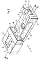
- FIG 1 and Figure 3 show a test strip analysis system 1, the evaluation device 2 with a test strip holder 3 and test strips 4 comprises.
- the test strips 4 (from which only one is shown) have an elastic Base layer 5, which is usually made of a plastic material exists and a test field 6.
- the one shown Test strip 4 is a so-called “non-wiping" (non wipe) "test strips. Passes through on these test strips the body fluid after being on top of the test field is applied, the entire thickness that of several layers 6a-6c (Fig.3) Test field 6. There are chemical reactions between the body fluid and that contained in the test field 6 Reagents instead.
- a resulting optically detectable Change in a detection layer 6c can reflective photometric from the underside 21 of the test strip can be detected.
- the base layer 5 of the test strip 4 in Area of the test field 6 has a measurement opening for this purpose 7.
- the test strip 4 can be in three in its longitudinal direction Sections are divided.
- the test field 6 defines a test field area 13. Since the test strip 4 in the illustrated If only one test field has 6, the test field area 13 through the front edge 8 and rear Edge 9 of the test field 6 is limited.
- the invention is suitable but also for test strips in which in one larger test field area several test fields in a row are arranged.
- the test field area extends in this case in insertion direction A from the front Edge of the first test field to the rear edge of the last test field.
- the test strip 6 has in the Front portion 12 near the front end 10 a circular recess 17 which in the transverse direction of the Test strip 6 is arranged in the middle.
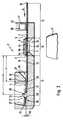
- the test strip 4 In the measuring position shown in Figure 3 is the test strip 4 in such a way the test strip pad 20 that the median plane 22 of the Test field area 13 a defined distance from one Has measuring unit 11, which is below the measurement opening 23 of the test strip support 20 is located.
- a middle level 22 of the test field area 13 As shown in FIG. 3 can be seen, which in the test field area 13 by the Center of the base layer 5 of the test strip 4 called geometric plane.
- Part of the test strip pad 20 is in the area in which the front section 12 is in the measuring position, formed as a support 24, which in height offset from the center plane 22 of the test field area 6 is. In other words, between is, at the test strip rests on the support 24, and the central plane 22 a defined vertical distance available.
- a stationary conical holding mandrel 26 at the same time as a support 24 and as a fixing element 25 for fixing the position of the test strip 4 in its longitudinal direction, wherein the insertion movement of the test strip 4 by a Stop 32 is limited.
- the holding mandrel 26 it is important that it one to the surface of the test strip (in the area of the Recess 17) inclined towards the stop 32 (at an acute angle to the test strip surface extending) lateral surface 27 and the test strip support 20 designed in the vicinity of the holding mandrel 26 is that the test strip 4 is in its the front end 10 facing foremost section defined only two Has points of contact, namely that he with his Front end 10 abuts the stop 32 and with a the front end 10 facing portion 28 of the edge of the Recess 17 on the inclined lateral surface 27 of the holding mandrel 26 rests.
- the distance between the center of the mandrel 26 and the stop 32 is slightly smaller than that Distance between the center of the recess 17 and the front end 10 of the test strip 4.
- test strip 4 (downwards) in the direction of the test strip support 20 (in the area of the holding mandrel 26) through the support 24 formed by the lateral surface 27 limited.
- the distance of the support 24 from the median plane 22 of the test field area 13 is in the figure with ie designated.
- the support 24 is so in this case ie offset from the central plane 22.
- the test strip holder 3 has a stationary pressure element 33 on which the test strip support 20 spanned like a bridge.
- the amount of between the stationary Pressure element 33 and the test strip support 20 formed gap 36 through which the test strip 4 at Introduced into the test strip holder 3 is at least 1.5 times the thickness of the Base layer 5.
- the pressure element 33 presses approximately in the middle of the front section 12 against the second Side (top) 34 of the test strip 4.
- the surface 35, with which the pressure element 33 touches the test strip 4 is closer to the central plane 22 than the support 24, so that the test strip 4 in the measuring position under bending stress stands. Due to the elasticity of the base layer 5 the test strip in the test field area 13 against the Test strip support 20 pressed and thus the defined Distance of the test field 6 from the measuring unit 11 ensured.
- the end face 37 of the pressure element 33 funnel-shaped.
- the front end also becomes geometrical 10 of the test strip 4 down against the holding mandrel 26 pressed. This also makes positioning of the test strip 4 in the longitudinal direction, because the recess 17 on the inclined lateral surface 27 slides towards the stop 32 and thus (by the own elasticity of the base layer 5) a force component in the longitudinal direction of the test strip 4 on the stop 32 acts.
- the distance a of the stationary is preferably Pressure element 33 from the front end 10 of the test strip 4 facing limitation of the test field area 13 between 0.35 and 0.65 times the distance b between the boundary facing the front end 10 of the test field area 13 and the support 24.
- the length of the test strip support 20 shorter than the length of the test strip 4, so that only a part facing the test field area 13 of the handling section 15 on the test strip support 20 rests.
- the other part of the handling section 15 protrudes freely from the evaluation device 2, what the Handling of the test strip 4 facilitated.
- the test strip holder has 3 for inserting the test strips 4 and for exact Transverse positioning a guide 40.
- Dependent on on the rigidity of the base layer of the test strips can vary in the area of the handling section 15 be designed.
- the base layer is relative stiff, it is sufficient if the lead in This area prevents transverse movements of the test strips. This can be done, for example, by two guide elements with parallel to the direction of insertion and perpendicular from the guiding surfaces uplifting the test strip support can be achieved, the distance from each other something is larger than the width of the test strips.
- FIGS to 3 illustrated embodiment is in the range of the handling section 15 laterally at the end of the test strip support 20 each have an elastic spring element 39 in Form of elastic spiral springs 41 arranged. This are fastened in corresponding receptacles 42.
- the spiral springs 41 each protrude with a segment of a circle Profile out of the recordings 42, being above the test strip support 20 the smallest distance from each other to have. In the amount of one on the test strip support 20 the test strip is slightly closer than its width. This allows a test strip 4 between the spiral springs 41 elastically clamped and fixed will.
- the guide 40 in the area of the front section 12 is through the test strip support 20 delimiting wall surfaces 43.44 formed perpendicular to the test strip pad 20 raise. Form starting from the pressure element 33 the wall surfaces 43, 44 first a tapered Lateral guide, then at a constant distance from each other, which is slightly larger than the width of a test strip 4 is to run up to the stop 32.
- test strip 4 If a test strip 4 is to be inserted into the evaluation device 2 be, with its front end 10 it is obliquely from inserted at the top into the gap 36 of the test strip holder 3. With the further insertion movement the front end 10 through the opposite of the test strip overlay 20 raised mandrel 26 raised. As soon as the holding mandrel 26 engages in the recess 17, arises from the after elastic tension of the test strip 4 acting at the bottom and the oblique inclination of the lateral surface 27 of the holding mandrel 26 the force component described on the stop 32 to. The test strip 4 slides in the direction the stop 32 until it defines the one shown in FIG Has reached the measuring position.
- the handle end 16 is manually against the resistance the spiral springs 41 down against the test strip support 20 pressed and fixed there by the spiral springs 41.
- FIG. 4 shows a section of an alternative one Embodiment of the invention shown.
- the difference to the previously described embodiment essential in that this test strip analysis system without a stop in the area of the front end. All other features of the previously described embodiment are also realized in this.
- the Holding mandrel 50 and the recess 17 of the test strip 4 have circular cross sections, which means that the test strip 4 in its measuring position centrally and with the edge of the recess 17 essentially completely on the lateral surface 53 of the holding mandrel 50 rests and thereby fixed is.
Landscapes
- Health & Medical Sciences (AREA)
- Life Sciences & Earth Sciences (AREA)
- Immunology (AREA)
- Hematology (AREA)
- Engineering & Computer Science (AREA)
- Chemical & Material Sciences (AREA)
- Molecular Biology (AREA)
- Biomedical Technology (AREA)
- Urology & Nephrology (AREA)
- General Physics & Mathematics (AREA)
- Analytical Chemistry (AREA)
- Pathology (AREA)
- General Health & Medical Sciences (AREA)
- Biochemistry (AREA)
- Physics & Mathematics (AREA)
- Biotechnology (AREA)
- Medicinal Chemistry (AREA)
- Food Science & Technology (AREA)
- Cell Biology (AREA)
- Microbiology (AREA)
- Automatic Analysis And Handling Materials Therefor (AREA)
- Investigating Or Analysing Biological Materials (AREA)
- Investigating Or Analysing Materials By The Use Of Chemical Reactions (AREA)
- Investigating Strength Of Materials By Application Of Mechanical Stress (AREA)
- Investigating Or Analyzing Non-Biological Materials By The Use Of Chemical Means (AREA)
- Analysing Materials By The Use Of Radiation (AREA)
- Medicines Containing Antibodies Or Antigens For Use As Internal Diagnostic Agents (AREA)
- Testing Of Devices, Machine Parts, Or Other Structures Thereof (AREA)
- Polishing Bodies And Polishing Tools (AREA)
- Mechanical Treatment Of Semiconductor (AREA)
- Detergent Compositions (AREA)
- Fodder In General (AREA)
- Seasonings (AREA)
- Tires In General (AREA)
- Sampling And Sample Adjustment (AREA)
- Materials For Medical Uses (AREA)
Applications Claiming Priority (3)
| Application Number | Priority Date | Filing Date | Title |
|---|---|---|---|
| DE4310583A DE4310583A1 (de) | 1993-03-31 | 1993-03-31 | Teststreifenanalysesystem |
| DE4310583 | 1993-03-31 | ||
| EP94104267A EP0618443B1 (fr) | 1993-03-31 | 1994-03-18 | Analyseur pour bandes de test |
Related Parent Applications (2)
| Application Number | Title | Priority Date | Filing Date |
|---|---|---|---|
| EP94104267.3 Division | 1994-03-18 | ||
| EP94104267A Division EP0618443B1 (fr) | 1993-03-31 | 1994-03-18 | Analyseur pour bandes de test |
Publications (3)
| Publication Number | Publication Date |
|---|---|
| EP0816831A2 true EP0816831A2 (fr) | 1998-01-07 |
| EP0816831A3 EP0816831A3 (fr) | 1998-01-28 |
| EP0816831B1 EP0816831B1 (fr) | 2003-05-14 |
Family
ID=6484401
Family Applications (2)
| Application Number | Title | Priority Date | Filing Date |
|---|---|---|---|
| EP94104267A Expired - Lifetime EP0618443B1 (fr) | 1993-03-31 | 1994-03-18 | Analyseur pour bandes de test |
| EP97112668A Expired - Lifetime EP0816831B1 (fr) | 1993-03-31 | 1994-03-18 | Dispositif pour l'évaluation de bandes de test |
Family Applications Before (1)
| Application Number | Title | Priority Date | Filing Date |
|---|---|---|---|
| EP94104267A Expired - Lifetime EP0618443B1 (fr) | 1993-03-31 | 1994-03-18 | Analyseur pour bandes de test |
Country Status (23)
| Country | Link |
|---|---|
| US (1) | US5424035A (fr) |
| EP (2) | EP0618443B1 (fr) |
| JP (1) | JP2505710B2 (fr) |
| KR (1) | KR0136998B1 (fr) |
| CN (1) | CN1046035C (fr) |
| AT (2) | ATE166720T1 (fr) |
| AU (1) | AU656286B2 (fr) |
| BR (1) | BR9401326A (fr) |
| CA (1) | CA2119816C (fr) |
| CZ (1) | CZ289858B6 (fr) |
| DE (3) | DE4310583A1 (fr) |
| DK (2) | DK0618443T3 (fr) |
| ES (2) | ES2196220T3 (fr) |
| FI (1) | FI108578B (fr) |
| HK (1) | HK1008441A1 (fr) |
| HU (1) | HU216502B (fr) |
| IL (1) | IL109172A (fr) |
| NO (1) | NO316297B1 (fr) |
| NZ (1) | NZ260197A (fr) |
| RU (1) | RU2093834C1 (fr) |
| SI (1) | SI9400160A (fr) |
| TW (1) | TW248591B (fr) |
| ZA (1) | ZA942248B (fr) |
Cited By (1)
| Publication number | Priority date | Publication date | Assignee | Title |
|---|---|---|---|---|
| WO2001038859A1 (fr) * | 1999-11-24 | 2001-05-31 | Home Diagnostics, Inc. | Plate-forme protectrice de bande d'essai pour dispositif de mesure optique |
Families Citing this family (94)
| Publication number | Priority date | Publication date | Assignee | Title |
|---|---|---|---|---|
| US5515170A (en) * | 1994-09-08 | 1996-05-07 | Lifescan, Inc. | Analyte detection device having a serpentine passageway for indicator strips |
| US5728352A (en) * | 1994-11-14 | 1998-03-17 | Advanced Care Products | Disposable electronic diagnostic instrument |
| DE19611347A1 (de) * | 1996-03-22 | 1997-09-25 | Boehringer Mannheim Gmbh | System zur quantitativen ortsaufgelösten Auswertung von Testelementen |
| FI112029B (fi) * | 1996-09-02 | 2003-10-31 | Nokia Corp | Laite nestemäisten näytteiden, kuten verinäytteiden ottamiseksi ja analysoimiseksi |
| CN1240027A (zh) * | 1996-10-30 | 1999-12-29 | 莫克里诊断公司 | 被校准的分析物化验系统 |
| AU6157898A (en) | 1997-02-06 | 1998-08-26 | E. Heller & Company | Small volume (in vitro) analyte sensor |
| US20050101032A1 (en) * | 1997-02-10 | 2005-05-12 | Metrika, Inc. | Assay device, composition, and method of optimizing assay sensitivity |
| FI111217B (fi) * | 1997-06-19 | 2003-06-30 | Nokia Corp | Laite näytteiden ottamiseksi |
| US6009632A (en) * | 1997-12-12 | 2000-01-04 | Mercury Diagnostics, Inc. | Alignment system for optical analyte testing meter components |
| DE19755529A1 (de) | 1997-12-13 | 1999-06-17 | Roche Diagnostics Gmbh | Analysensystem für Probenflüssigkeiten |
| US8071384B2 (en) | 1997-12-22 | 2011-12-06 | Roche Diagnostics Operations, Inc. | Control and calibration solutions and methods for their use |
| US6267722B1 (en) | 1998-02-03 | 2001-07-31 | Adeza Biomedical Corporation | Point of care diagnostic systems |
| US6394952B1 (en) | 1998-02-03 | 2002-05-28 | Adeza Biomedical Corporation | Point of care diagnostic systems |
| US6103033A (en) | 1998-03-04 | 2000-08-15 | Therasense, Inc. | Process for producing an electrochemical biosensor |
| US5995236A (en) * | 1998-04-13 | 1999-11-30 | Mit Development Corporation | Blood fluid characteristics analysis instrument |
| USD432244S (en) * | 1998-04-20 | 2000-10-17 | Adeza Biomedical Corporation | Device for encasing an assay test strip |
| USD434153S (en) * | 1998-04-20 | 2000-11-21 | Adeza Biomedical Corporation | Point of care analyte detector system |
| US20060019404A1 (en) * | 1998-05-06 | 2006-01-26 | Blatt Joel M | Quantitative assay with extended dynamic range |
| DE19822770B4 (de) * | 1998-05-20 | 2012-04-12 | Lre Technology Partner Gmbh | Teststreifensystem |
| DE19844500A1 (de) | 1998-09-29 | 2000-03-30 | Roche Diagnostics Gmbh | Verfahren zur photometrischen Auswertung von Testelementen |
| US6338790B1 (en) | 1998-10-08 | 2002-01-15 | Therasense, Inc. | Small volume in vitro analyte sensor with diffusible or non-leachable redox mediator |
| DE19926931A1 (de) * | 1999-06-14 | 2000-12-21 | Roche Diagnostics Gmbh | Verfahren und Vorrichtung zur Kontrolle der Flüssigkeitsaufnahme einer Testschicht eines Analyseelementes |
| US20050103624A1 (en) | 1999-10-04 | 2005-05-19 | Bhullar Raghbir S. | Biosensor and method of making |
| GB2365526B (en) * | 2000-07-31 | 2003-12-03 | Cambridge Life Sciences | Assay apparatus for measuring the amount of an analyte in a biological or environmental sample |
| US6652814B1 (en) * | 2000-08-11 | 2003-11-25 | Lifescan, Inc. | Strip holder for use in a test strip meter |
| DE10061336A1 (de) | 2000-12-08 | 2002-06-13 | Roche Diagnostics Gmbh | System zur Analyse von Probeflüssigkeiten beinhaltend eine Lagekontrolleinheit |
| US6541266B2 (en) | 2001-02-28 | 2003-04-01 | Home Diagnostics, Inc. | Method for determining concentration of an analyte in a test strip |
| US6562625B2 (en) | 2001-02-28 | 2003-05-13 | Home Diagnostics, Inc. | Distinguishing test types through spectral analysis |
| US6525330B2 (en) | 2001-02-28 | 2003-02-25 | Home Diagnostics, Inc. | Method of strip insertion detection |
| US6576416B2 (en) * | 2001-06-19 | 2003-06-10 | Lifescan, Inc. | Analyte measurement device and method of use |
| DE10163775A1 (de) | 2001-12-22 | 2003-07-03 | Roche Diagnostics Gmbh | Analysensystem zur Bestimmung einer Analytkonzentration unter Berücksichtigung von proben- und analytunabhängigen Lichtintensitätsänderungen |
| US6759190B2 (en) * | 2002-06-15 | 2004-07-06 | Acon Laboratories, Inc. | Test strip for detection of analyte and methods of use |
| US20040018114A1 (en) * | 2002-07-26 | 2004-01-29 | Chia-Lin Wang | Test strip holder for a reagent test strip |
| US7572237B2 (en) * | 2002-11-06 | 2009-08-11 | Abbott Diabetes Care Inc. | Automatic biological analyte testing meter with integrated lancing device and methods of use |
| US20040096363A1 (en) * | 2002-11-18 | 2004-05-20 | Larry Porter | Point-of-care assay reader and analyzer |
| WO2004057345A2 (fr) * | 2002-12-23 | 2004-07-08 | Roche Diagnostics Gmbh | Dispositif de transport servant a transporter des elements de test dans un systeme d'analyse |
| DE10325699B3 (de) * | 2003-06-06 | 2005-02-10 | Roche Diagnostics Gmbh | System zur Analyse einer zu untersuchenden Probe und Verwendung eines solchen Systems |
| US8206565B2 (en) | 2003-06-20 | 2012-06-26 | Roche Diagnostics Operation, Inc. | System and method for coding information on a biosensor test strip |
| US7452457B2 (en) | 2003-06-20 | 2008-11-18 | Roche Diagnostics Operations, Inc. | System and method for analyte measurement using dose sufficiency electrodes |
| US7718439B2 (en) | 2003-06-20 | 2010-05-18 | Roche Diagnostics Operations, Inc. | System and method for coding information on a biosensor test strip |
| US7645373B2 (en) | 2003-06-20 | 2010-01-12 | Roche Diagnostic Operations, Inc. | System and method for coding information on a biosensor test strip |
| US7645421B2 (en) | 2003-06-20 | 2010-01-12 | Roche Diagnostics Operations, Inc. | System and method for coding information on a biosensor test strip |
| US8071030B2 (en) | 2003-06-20 | 2011-12-06 | Roche Diagnostics Operations, Inc. | Test strip with flared sample receiving chamber |
| US7488601B2 (en) | 2003-06-20 | 2009-02-10 | Roche Diagnostic Operations, Inc. | System and method for determining an abused sensor during analyte measurement |
| US8058077B2 (en) | 2003-06-20 | 2011-11-15 | Roche Diagnostics Operations, Inc. | Method for coding information on a biosensor test strip |
| US8679853B2 (en) | 2003-06-20 | 2014-03-25 | Roche Diagnostics Operations, Inc. | Biosensor with laser-sealed capillary space and method of making |
| US8148164B2 (en) | 2003-06-20 | 2012-04-03 | Roche Diagnostics Operations, Inc. | System and method for determining the concentration of an analyte in a sample fluid |
| JP4619359B2 (ja) | 2003-06-20 | 2011-01-26 | エフ ホフマン−ラ ロッシュ アクチェン ゲゼルシャフト | フレア状に形成された試料受入チャンバーを持つ試験片 |
| DE10338446A1 (de) | 2003-08-21 | 2005-03-31 | Roche Diagnostics Gmbh | Positioniereinrichtung für ein Testelement |
| US7588733B2 (en) * | 2003-12-04 | 2009-09-15 | Idexx Laboratories, Inc. | Retaining clip for reagent test slides |
| US7150995B2 (en) * | 2004-01-16 | 2006-12-19 | Metrika, Inc. | Methods and systems for point of care bodily fluid analysis |
| WO2005078118A1 (fr) | 2004-02-06 | 2005-08-25 | Bayer Healthcare Llc | Especes oxydables servant de reference interne a des biocapteurs, et procede d'utilisation |
| DE102004008539A1 (de) * | 2004-02-19 | 2005-09-01 | Prionics Ag | Vorrichtung und Verfahren zur optischen Auswertung von Teststreifen |
| DE102004022757B4 (de) * | 2004-05-07 | 2006-11-02 | Lre Technology Partner Gmbh | Streifenauswerfer |
| US7569126B2 (en) | 2004-06-18 | 2009-08-04 | Roche Diagnostics Operations, Inc. | System and method for quality assurance of a biosensor test strip |
| DE102004036474A1 (de) * | 2004-07-28 | 2006-03-23 | Roche Diagnostics Gmbh | Analysesystem zur Analyse einer Probe auf einem Testelement |
| US20060133956A1 (en) * | 2004-12-09 | 2006-06-22 | Kenichi Hamanaka | Test strip holder |
| DE502005002762D1 (de) | 2005-06-22 | 2008-03-20 | Roche Diagnostics Gmbh | Analysesystem zur Analyse einer Probe auf einem analytischen Testelement |
| MX2008000836A (es) | 2005-07-20 | 2008-03-26 | Bayer Healthcare Llc | Amperimetria regulada. |
| EP1934591B1 (fr) | 2005-09-30 | 2019-01-02 | Ascensia Diabetes Care Holdings AG | Voltamperometrie commandee |
| EP1780541B1 (fr) | 2005-10-25 | 2008-10-15 | F.Hoffmann-La Roche Ag | Appareil d'analyse destiné à l'analyse d'un échantillon sur un élément de test |
| EP1879018B1 (fr) | 2006-07-12 | 2015-08-19 | F. Hoffmann-La Roche AG | Système d'analyse et procédé destinés à l'analyse d'un échantillon sur un élément de test analytique |
| US7740580B2 (en) * | 2006-10-31 | 2010-06-22 | Abbott Diabetes Care Inc. | Analyte monitoring |
| PL1921441T3 (pl) | 2006-11-07 | 2014-02-28 | Hoffmann La Roche | Sposób analizowania próbki na elemencie testowym i system analityczny |
| JP5249534B2 (ja) * | 2007-07-09 | 2013-07-31 | 大塚製薬株式会社 | 試験紙測定容器 |
| DE102007054309A1 (de) | 2007-11-08 | 2009-05-14 | Laser- und Medizin-Technologie GmbH, Berlin (LMTB) | Optische Anordnung zur Erhöhung der Wechselwirkungslänge in stark steuernder Matrix |
| WO2009076302A1 (fr) | 2007-12-10 | 2009-06-18 | Bayer Healthcare Llc | Marqueurs de contrôle pour la détection automatique d'une solution de contrôle et procédés d'utilisation |
| CN101620224B (zh) * | 2008-06-30 | 2014-06-04 | 艾博生物医药(杭州)有限公司 | 用于装配检测装置的工具及使用方法 |
| US9218453B2 (en) * | 2009-06-29 | 2015-12-22 | Roche Diabetes Care, Inc. | Blood glucose management and interface systems and methods |
| US20100331652A1 (en) | 2009-06-29 | 2010-12-30 | Roche Diagnostics Operations, Inc. | Modular diabetes management systems |
| US8622231B2 (en) | 2009-09-09 | 2014-01-07 | Roche Diagnostics Operations, Inc. | Storage containers for test elements |
| EP2325624A1 (fr) * | 2009-11-18 | 2011-05-25 | F. Hoffmann-La Roche AG | Procédé et dispositif destinés à l'examen d'un liquide corporel |
| US20110151571A1 (en) | 2009-12-23 | 2011-06-23 | Roche Diagnostics Operations, Inc. | Memory apparatus for multiuse analyte test element systems, and kits, systems, combinations and methods relating to same |
| US20110186428A1 (en) | 2010-01-29 | 2011-08-04 | Roche Diagnostics Operations, Inc. | Electrode arrangements for biosensors |
| CA2810650C (fr) | 2010-09-07 | 2019-12-03 | Nextteq Llc | Systeme de lecture visuelle et electronique de tubes colorimetriques |
| US11175234B2 (en) | 2010-09-07 | 2021-11-16 | Nextteq Llc | System for visual and electronic reading of colorimetric tubes |
| US20120143085A1 (en) | 2010-12-02 | 2012-06-07 | Matthew Carlyle Sauers | Test element ejection mechanism for a meter |
| JP2012177677A (ja) * | 2011-02-02 | 2012-09-13 | Arkray Inc | 分析装置 |
| US9914126B2 (en) | 2011-11-28 | 2018-03-13 | Roche Diabetes Care, Inc. | Storage container for biosensor test elements |
| US9572922B2 (en) | 2012-12-21 | 2017-02-21 | Larry Leonard | Inventive diabetic systems, tools, kits, and supplies for better diabetic living and mobility |
| KR101401257B1 (ko) * | 2012-03-30 | 2014-05-29 | 서울대학교산학협력단 | 비정질 금속재료의 변형정도 모니터링 방법과 이를 위한 굽힘시험 방법 및 장치 |
| KR101388764B1 (ko) * | 2012-08-31 | 2014-04-25 | 주식회사 인포피아 | 검체 분석용 키트 및 이를 포함하는 검체 분석 장치 |
| EP2703803A3 (fr) | 2012-08-31 | 2014-05-07 | Infopia Co., Ltd. | Boîtier pour kit d'analyse d'échantillons, kit d'analyse d'échantillons, appareil d'analyse d'échantillon et procédé de commande d'un appareil d'analyse d'échantillon |
| USD717677S1 (en) * | 2013-03-14 | 2014-11-18 | Hanna Instruments, Inc. | Meter |
| EP2974655B1 (fr) * | 2014-07-15 | 2017-04-12 | Roche Diabetes Care GmbH | Éjecteur de bande test de poignée |
| JP6557231B2 (ja) | 2013-11-27 | 2019-08-07 | エフ.ホフマン−ラ ロシュ アーゲーF. Hoffmann−La Roche Aktiengesellschaft | ハンドグリップ式テストテープエジェクタ |
| JP6612762B2 (ja) | 2014-09-29 | 2019-11-27 | テルモ株式会社 | 成分測定装置及び測定用チップ |
| DE102014226381A1 (de) * | 2014-12-18 | 2016-06-23 | Robert Bosch Gmbh | Halteeinrichtung, System und Verfahren zur optischen Auslesung eines Teststreifens |
| US9995743B2 (en) * | 2015-07-01 | 2018-06-12 | Htc Corporation | Test apparatus and pressurizing assembly thereof |
| USD865992S1 (en) * | 2015-11-02 | 2019-11-05 | Jon A. Petty | Fluid test strip |
| CN108408260B (zh) * | 2018-03-19 | 2020-04-10 | 中国科学院物理研究所 | 样品存储锁定装置 |
| DE102018208049A1 (de) * | 2018-05-23 | 2019-11-28 | Robert Bosch Gmbh | Gerüststruktur zum Zusammenwirken mit einer Bildauswertevorrichtung für zumindest einen mindestens eine optochemische Detektierfläche aufweisenden Träger |
| US11517896B2 (en) * | 2020-08-14 | 2022-12-06 | Luna Pharmaceuticals, Inc. | Test strip holder |
| CN113406029B (zh) * | 2021-03-25 | 2023-04-07 | 江苏硕世生物科技股份有限公司 | 检测结果读取装置 |
Citations (5)
| Publication number | Priority date | Publication date | Assignee | Title |
|---|---|---|---|---|
| EP0129220A2 (fr) * | 1983-06-16 | 1984-12-27 | Roche Diagnostics GmbH | Dispositif pour l'évaluation d'un ruban de test à réactif pour la détermination analytique de constituants d'un liquide corporel |
| EP0183524A2 (fr) * | 1984-11-27 | 1986-06-04 | Syntex (U.S.A.) Inc. | Analyseur portable |
| EP0319922A2 (fr) * | 1987-12-09 | 1989-06-14 | Lre Relais + Elektronik Gmbh | Dispositif pour la lecture optique d'un ruban test présentant au moins un champ d'épreuve |
| EP0376111A2 (fr) * | 1988-12-28 | 1990-07-04 | Roche Diagnostics GmbH | Analyseur pour bandes de test |
| EP0492326A2 (fr) * | 1990-12-27 | 1992-07-01 | Roche Diagnostics GmbH | Analyseur pour bandes de test |
Family Cites Families (7)
| Publication number | Priority date | Publication date | Assignee | Title |
|---|---|---|---|---|
| DE3625705A1 (de) * | 1986-07-30 | 1988-02-11 | Hoechst Ag | Vorrichtung zum automatischen zufuehren von teststreifen in eine analysenapparatur |
| DE3625704A1 (de) * | 1986-07-30 | 1988-02-11 | Hoechst Ag | Vorrichtung zum feststellen der lage der testfelder eines teststreifens und wenden desselben |
| JPH0542351Y2 (fr) * | 1988-03-14 | 1993-10-26 | ||
| AU635314B2 (en) * | 1989-09-08 | 1993-03-18 | Terumo Kabushiki Kaisha | Measuring apparatus |
| AU7392791A (en) * | 1990-03-29 | 1991-10-03 | Phosphate Co-Operative Company of Australia Limited, The | A device for use in measuring chemical concentrations |
| DE4015590A1 (de) * | 1990-05-15 | 1991-11-21 | Boehringer Mannheim Gmbh | Testtraeger zur bestimmung von ionen |
| US5232668A (en) * | 1991-02-27 | 1993-08-03 | Boehringer Mannheim Corporation | Test strip holding and reading mechanism for a meter |
-
1993
- 1993-03-31 DE DE4310583A patent/DE4310583A1/de not_active Withdrawn
-
1994
- 1994-02-07 AU AU54923/94A patent/AU656286B2/en not_active Ceased
- 1994-03-18 ES ES97112668T patent/ES2196220T3/es not_active Expired - Lifetime
- 1994-03-18 EP EP94104267A patent/EP0618443B1/fr not_active Expired - Lifetime
- 1994-03-18 AT AT94104267T patent/ATE166720T1/de active
- 1994-03-18 DK DK94104267T patent/DK0618443T3/da active
- 1994-03-18 AT AT97112668T patent/ATE240517T1/de active
- 1994-03-18 EP EP97112668A patent/EP0816831B1/fr not_active Expired - Lifetime
- 1994-03-18 DE DE59406067T patent/DE59406067D1/de not_active Expired - Lifetime
- 1994-03-18 DE DE59410286T patent/DE59410286D1/de not_active Expired - Lifetime
- 1994-03-18 DK DK97112668T patent/DK0816831T3/da active
- 1994-03-18 ES ES94104267T patent/ES2117731T3/es not_active Expired - Lifetime
- 1994-03-21 KR KR1019940005577A patent/KR0136998B1/ko not_active IP Right Cessation
- 1994-03-22 TW TW083102500A patent/TW248591B/zh not_active IP Right Cessation
- 1994-03-24 CA CA002119816A patent/CA2119816C/fr not_active Expired - Lifetime
- 1994-03-28 NZ NZ260197A patent/NZ260197A/en unknown
- 1994-03-28 JP JP6057035A patent/JP2505710B2/ja not_active Expired - Lifetime
- 1994-03-29 BR BR9401326A patent/BR9401326A/pt not_active Application Discontinuation
- 1994-03-29 US US08/219,479 patent/US5424035A/en not_active Expired - Lifetime
- 1994-03-29 CZ CZ1994736A patent/CZ289858B6/cs not_active IP Right Cessation
- 1994-03-30 IL IL109172A patent/IL109172A/xx not_active IP Right Cessation
- 1994-03-30 RU RU9494010095A patent/RU2093834C1/ru active
- 1994-03-30 HU HU9400916A patent/HU216502B/hu not_active IP Right Cessation
- 1994-03-30 CN CN94103446A patent/CN1046035C/zh not_active Expired - Lifetime
- 1994-03-30 ZA ZA942248A patent/ZA942248B/xx unknown
- 1994-03-30 NO NO19941194A patent/NO316297B1/no not_active IP Right Cessation
- 1994-03-30 FI FI941495A patent/FI108578B/fi not_active IP Right Cessation
- 1994-03-31 SI SI9400160A patent/SI9400160A/sl unknown
-
1998
- 1998-07-17 HK HK98109255A patent/HK1008441A1/xx not_active IP Right Cessation
Patent Citations (5)
| Publication number | Priority date | Publication date | Assignee | Title |
|---|---|---|---|---|
| EP0129220A2 (fr) * | 1983-06-16 | 1984-12-27 | Roche Diagnostics GmbH | Dispositif pour l'évaluation d'un ruban de test à réactif pour la détermination analytique de constituants d'un liquide corporel |
| EP0183524A2 (fr) * | 1984-11-27 | 1986-06-04 | Syntex (U.S.A.) Inc. | Analyseur portable |
| EP0319922A2 (fr) * | 1987-12-09 | 1989-06-14 | Lre Relais + Elektronik Gmbh | Dispositif pour la lecture optique d'un ruban test présentant au moins un champ d'épreuve |
| EP0376111A2 (fr) * | 1988-12-28 | 1990-07-04 | Roche Diagnostics GmbH | Analyseur pour bandes de test |
| EP0492326A2 (fr) * | 1990-12-27 | 1992-07-01 | Roche Diagnostics GmbH | Analyseur pour bandes de test |
Cited By (1)
| Publication number | Priority date | Publication date | Assignee | Title |
|---|---|---|---|---|
| WO2001038859A1 (fr) * | 1999-11-24 | 2001-05-31 | Home Diagnostics, Inc. | Plate-forme protectrice de bande d'essai pour dispositif de mesure optique |
Also Published As
Similar Documents
| Publication | Publication Date | Title |
|---|---|---|
| EP0816831B1 (fr) | Dispositif pour l'évaluation de bandes de test | |
| EP0319922B1 (fr) | Dispositif pour la lecture optique d'un ruban test présentant au moins un champ d'épreuve | |
| EP0431455B1 (fr) | Dispositif d'évaluation de bandes à essais multiples | |
| DE19822770B4 (de) | Teststreifensystem | |
| DD222124A5 (de) | Geraet zur auswertung eines testtraegers zur analytischen bestimmung von bestandteilen einer koerperfluessigkeit | |
| DE69405116T2 (de) | Nachweis vorrichtung und herstellungsverfahren dafür | |
| EP1574855A1 (fr) | Appareil portable d'analyse | |
| DE10061336A1 (de) | System zur Analyse von Probeflüssigkeiten beinhaltend eine Lagekontrolleinheit | |
| EP0376111B1 (fr) | Analyseur pour bandes de test | |
| EP1621885B1 (fr) | Système d'analyse avec un support pour des élements analytiques | |
| DE3881650T2 (de) | Reflektionsplättchen für ein biochemisches Messinstrument. | |
| DE69103437T2 (de) | Vorrichtung zum automatischen Verschliessen einer Pipettenspitze. | |
| DE102004022757B4 (de) | Streifenauswerfer | |
| DE69617283T2 (de) | Vorrichtung zum Anpressen von Elementen in einer Kassette für trockene chemische Analyseelemente | |
| EP4091715A1 (fr) | Syst?me de bandelette réactive pourvu de récipients | |
| DE60308314T2 (de) | Antriebsvorrichtung einer küvettenkette in einer analysevorrichtung | |
| EP0405513B1 (fr) | Dispositif pour l'analyse photométrique par rémission d'échantillons liquides | |
| DE602004008759T2 (de) | Ständersystem mit Adapter | |
| CH712081A2 (de) | Vorrichtung zum visuellen Nachweis von Analyten in einer flüssigen Probe. | |
| DE4035052C2 (de) | Testträgeranalysegerät | |
| EP0940181B1 (fr) | Plaque à pointes avec un support attaché par brochage ou par adhésion | |
| EP2693943B1 (fr) | Système d'analyse avec dispositif de mesure et élément d'essai | |
| DE3851646T2 (de) | Probenübertragungsvorrichtung. | |
| EP1508807A2 (fr) | Unité de positionnement d'éléments de test | |
| EP0376109A2 (fr) | Analyseur pour bandes de test |
Legal Events
| Date | Code | Title | Description |
|---|---|---|---|
| PUAI | Public reference made under article 153(3) epc to a published international application that has entered the european phase |
Free format text: ORIGINAL CODE: 0009012 |
|
| PUAL | Search report despatched |
Free format text: ORIGINAL CODE: 0009013 |
|
| 17P | Request for examination filed |
Effective date: 19970818 |
|
| AC | Divisional application: reference to earlier application |
Ref document number: 618443 Country of ref document: EP |
|
| AK | Designated contracting states |
Kind code of ref document: A2 Designated state(s): AT BE CH DE DK ES FR GB IE IT LI NL SE |
|
| RBV | Designated contracting states (corrected) |
Designated state(s): AT BE CH DE DK ES FR GB IE IT LI NL SE |
|
| AK | Designated contracting states |
Kind code of ref document: A3 Designated state(s): AT BE CH DE DK ES FR GB IE IT LI NL SE |
|
| RBV | Designated contracting states (corrected) |
Designated state(s): AT BE CH DE DK ES FR GB GR IE IT LI LU NL PT SE |
|
| RBV | Designated contracting states (corrected) |
Designated state(s): AT BE CH DE DK ES FR GB IE IT LI NL SE |
|
| RAP3 | Party data changed (applicant data changed or rights of an application transferred) |
Owner name: ROCHE DIAGNOSTICS GMBH |
|
| 17Q | First examination report despatched |
Effective date: 20011112 |
|
| GRAH | Despatch of communication of intention to grant a patent |
Free format text: ORIGINAL CODE: EPIDOS IGRA |
|
| GRAH | Despatch of communication of intention to grant a patent |
Free format text: ORIGINAL CODE: EPIDOS IGRA |
|
| GRAA | (expected) grant |
Free format text: ORIGINAL CODE: 0009210 |
|
| AC | Divisional application: reference to earlier application |
Ref document number: 0618443 Country of ref document: EP Kind code of ref document: P |
|
| AK | Designated contracting states |
Designated state(s): AT BE CH DE DK ES FR GB IE IT LI NL SE |
|
| REG | Reference to a national code |
Ref country code: GB Ref legal event code: FG4D Free format text: NOT ENGLISH |
|
| REG | Reference to a national code |
Ref country code: CH Ref legal event code: NV Representative=s name: A. BRAUN, BRAUN, HERITIER, ESCHMANN AG PATENTANWAE Ref country code: CH Ref legal event code: EP |
|
| GBT | Gb: translation of ep patent filed (gb section 77(6)(a)/1977) |
Effective date: 20030515 |
|
| REG | Reference to a national code |
Ref country code: IE Ref legal event code: FG4D Free format text: GERMAN |
|
| REF | Corresponds to: |
Ref document number: 59410286 Country of ref document: DE Date of ref document: 20030618 Kind code of ref document: P |
|
| REG | Reference to a national code |
Ref country code: DK Ref legal event code: T3 |
|
| REG | Reference to a national code |
Ref country code: SE Ref legal event code: TRGR |
|
| ET | Fr: translation filed | ||
| REG | Reference to a national code |
Ref country code: ES Ref legal event code: FG2A Ref document number: 2196220 Country of ref document: ES Kind code of ref document: T3 |
|
| PLBE | No opposition filed within time limit |
Free format text: ORIGINAL CODE: 0009261 |
|
| STAA | Information on the status of an ep patent application or granted ep patent |
Free format text: STATUS: NO OPPOSITION FILED WITHIN TIME LIMIT |
|
| 26N | No opposition filed |
Effective date: 20040217 |
|
| REG | Reference to a national code |
Ref country code: CH Ref legal event code: PFA Owner name: ROCHE DIAGNOSTICS GMBH Free format text: ROCHE DIAGNOSTICS GMBH#SANDHOFER STRASSE 116#68305 MANNHEIM (DE) -TRANSFER TO- ROCHE DIAGNOSTICS GMBH#SANDHOFER STRASSE 116#68305 MANNHEIM (DE) |
|
| PGFP | Annual fee paid to national office [announced via postgrant information from national office to epo] |
Ref country code: DK Payment date: 20110221 Year of fee payment: 18 Ref country code: IE Payment date: 20110224 Year of fee payment: 18 |
|
| PGFP | Annual fee paid to national office [announced via postgrant information from national office to epo] |
Ref country code: CH Payment date: 20110125 Year of fee payment: 18 Ref country code: AT Payment date: 20110221 Year of fee payment: 18 Ref country code: SE Payment date: 20110307 Year of fee payment: 18 |
|
| PGFP | Annual fee paid to national office [announced via postgrant information from national office to epo] |
Ref country code: BE Payment date: 20110414 Year of fee payment: 18 |
|
| PGFP | Annual fee paid to national office [announced via postgrant information from national office to epo] |
Ref country code: IT Payment date: 20120321 Year of fee payment: 19 |
|
| BERE | Be: lapsed |
Owner name: *ROCHE DIAGNOSTICS G.M.B.H. Effective date: 20120331 |
|
| REG | Reference to a national code |
Ref country code: SE Ref legal event code: EUG |
|
| PG25 | Lapsed in a contracting state [announced via postgrant information from national office to epo] |
Ref country code: SE Free format text: LAPSE BECAUSE OF NON-PAYMENT OF DUE FEES Effective date: 20120319 |
|
| REG | Reference to a national code |
Ref country code: CH Ref legal event code: PL |
|
| REG | Reference to a national code |
Ref country code: DK Ref legal event code: EBP |
|
| REG | Reference to a national code |
Ref country code: AT Ref legal event code: MM01 Ref document number: 240517 Country of ref document: AT Kind code of ref document: T Effective date: 20120318 |
|
| REG | Reference to a national code |
Ref country code: IE Ref legal event code: MM4A |
|
| PG25 | Lapsed in a contracting state [announced via postgrant information from national office to epo] |
Ref country code: CH Free format text: LAPSE BECAUSE OF NON-PAYMENT OF DUE FEES Effective date: 20120331 Ref country code: LI Free format text: LAPSE BECAUSE OF NON-PAYMENT OF DUE FEES Effective date: 20120331 Ref country code: BE Free format text: LAPSE BECAUSE OF NON-PAYMENT OF DUE FEES Effective date: 20120331 Ref country code: AT Free format text: LAPSE BECAUSE OF NON-PAYMENT OF DUE FEES Effective date: 20120318 Ref country code: IE Free format text: LAPSE BECAUSE OF NON-PAYMENT OF DUE FEES Effective date: 20120318 |
|
| PG25 | Lapsed in a contracting state [announced via postgrant information from national office to epo] |
Ref country code: DK Free format text: LAPSE BECAUSE OF NON-PAYMENT OF DUE FEES Effective date: 20120331 |
|
| PGFP | Annual fee paid to national office [announced via postgrant information from national office to epo] |
Ref country code: GB Payment date: 20130225 Year of fee payment: 20 Ref country code: FR Payment date: 20130315 Year of fee payment: 20 Ref country code: ES Payment date: 20130313 Year of fee payment: 20 |
|
| PGFP | Annual fee paid to national office [announced via postgrant information from national office to epo] |
Ref country code: DE Payment date: 20130328 Year of fee payment: 20 |
|
| PGFP | Annual fee paid to national office [announced via postgrant information from national office to epo] |
Ref country code: NL Payment date: 20130312 Year of fee payment: 20 |
|
| REG | Reference to a national code |
Ref country code: DE Ref legal event code: R071 Ref document number: 59410286 Country of ref document: DE |
|
| REG | Reference to a national code |
Ref country code: NL Ref legal event code: V4 Effective date: 20140318 |
|
| REG | Reference to a national code |
Ref country code: GB Ref legal event code: PE20 Expiry date: 20140317 |
|
| PG25 | Lapsed in a contracting state [announced via postgrant information from national office to epo] |
Ref country code: GB Free format text: LAPSE BECAUSE OF EXPIRATION OF PROTECTION Effective date: 20140317 Ref country code: DE Free format text: LAPSE BECAUSE OF EXPIRATION OF PROTECTION Effective date: 20140319 |
|
| REG | Reference to a national code |
Ref country code: ES Ref legal event code: FD2A Effective date: 20140926 |
|
| PG25 | Lapsed in a contracting state [announced via postgrant information from national office to epo] |
Ref country code: ES Free format text: LAPSE BECAUSE OF EXPIRATION OF PROTECTION Effective date: 20140319 |