EP0816739A2 - Dispositif d'équilibrage amélioré pour arbres creux de transmission - Google Patents
Dispositif d'équilibrage amélioré pour arbres creux de transmission Download PDFInfo
- Publication number
- EP0816739A2 EP0816739A2 EP97108941A EP97108941A EP0816739A2 EP 0816739 A2 EP0816739 A2 EP 0816739A2 EP 97108941 A EP97108941 A EP 97108941A EP 97108941 A EP97108941 A EP 97108941A EP 0816739 A2 EP0816739 A2 EP 0816739A2
- Authority
- EP
- European Patent Office
- Prior art keywords
- clamp structure
- clamping band
- counterweight
- band
- rotating member
- Prior art date
- Legal status (The legal status is an assumption and is not a legal conclusion. Google has not performed a legal analysis and makes no representation as to the accuracy of the status listed.)
- Granted
Links
- 230000003014 reinforcing effect Effects 0.000 claims abstract description 12
- 230000000694 effects Effects 0.000 claims abstract description 4
- 239000000654 additive Substances 0.000 claims abstract 3
- 230000000996 additive effect Effects 0.000 claims abstract 3
- 230000002708 enhancing effect Effects 0.000 claims abstract 2
- 238000007373 indentation Methods 0.000 claims description 15
- 239000000463 material Substances 0.000 claims description 10
- 238000004873 anchoring Methods 0.000 claims description 9
- 229910001335 Galvanized steel Inorganic materials 0.000 claims description 2
- 239000008397 galvanized steel Substances 0.000 claims description 2
- 239000010935 stainless steel Substances 0.000 claims description 2
- 229910001220 stainless steel Inorganic materials 0.000 claims description 2
- 238000005452 bending Methods 0.000 claims 1
- 230000001419 dependent effect Effects 0.000 claims 1
- 230000002787 reinforcement Effects 0.000 description 15
- 238000010276 construction Methods 0.000 description 6
- 238000012986 modification Methods 0.000 description 4
- 230000004048 modification Effects 0.000 description 4
- 238000009434 installation Methods 0.000 description 3
- 238000004519 manufacturing process Methods 0.000 description 3
- 238000003466 welding Methods 0.000 description 3
- 239000010963 304 stainless steel Substances 0.000 description 1
- 229910000589 SAE 304 stainless steel Inorganic materials 0.000 description 1
- 239000000853 adhesive Substances 0.000 description 1
- 230000001070 adhesive effect Effects 0.000 description 1
- 239000000956 alloy Substances 0.000 description 1
- 229910045601 alloy Inorganic materials 0.000 description 1
- 238000011161 development Methods 0.000 description 1
- 230000018109 developmental process Effects 0.000 description 1
- 230000009977 dual effect Effects 0.000 description 1
- 210000005069 ears Anatomy 0.000 description 1
- 239000000203 mixture Substances 0.000 description 1
- 239000012255 powdered metal Substances 0.000 description 1
- 239000013585 weight reducing agent Substances 0.000 description 1
Images


Classifications
-
- F—MECHANICAL ENGINEERING; LIGHTING; HEATING; WEAPONS; BLASTING
- F16—ENGINEERING ELEMENTS AND UNITS; GENERAL MEASURES FOR PRODUCING AND MAINTAINING EFFECTIVE FUNCTIONING OF MACHINES OR INSTALLATIONS; THERMAL INSULATION IN GENERAL
- F16L—PIPES; JOINTS OR FITTINGS FOR PIPES; SUPPORTS FOR PIPES, CABLES OR PROTECTIVE TUBING; MEANS FOR THERMAL INSULATION IN GENERAL
- F16L33/00—Arrangements for connecting hoses to rigid members; Rigid hose connectors, i.e. single members engaging both hoses
- F16L33/02—Hose-clips
- F16L33/035—Hose-clips fixed by means of teeth or hooks
-
- F—MECHANICAL ENGINEERING; LIGHTING; HEATING; WEAPONS; BLASTING
- F16—ENGINEERING ELEMENTS AND UNITS; GENERAL MEASURES FOR PRODUCING AND MAINTAINING EFFECTIVE FUNCTIONING OF MACHINES OR INSTALLATIONS; THERMAL INSULATION IN GENERAL
- F16L—PIPES; JOINTS OR FITTINGS FOR PIPES; SUPPORTS FOR PIPES, CABLES OR PROTECTIVE TUBING; MEANS FOR THERMAL INSULATION IN GENERAL
- F16L33/00—Arrangements for connecting hoses to rigid members; Rigid hose connectors, i.e. single members engaging both hoses
- F16L33/02—Hose-clips
- F16L33/025—Hose-clips tightened by deforming radially extending loops or folds
-
- F—MECHANICAL ENGINEERING; LIGHTING; HEATING; WEAPONS; BLASTING
- F16—ENGINEERING ELEMENTS AND UNITS; GENERAL MEASURES FOR PRODUCING AND MAINTAINING EFFECTIVE FUNCTIONING OF MACHINES OR INSTALLATIONS; THERMAL INSULATION IN GENERAL
- F16B—DEVICES FOR FASTENING OR SECURING CONSTRUCTIONAL ELEMENTS OR MACHINE PARTS TOGETHER, e.g. NAILS, BOLTS, CIRCLIPS, CLAMPS, CLIPS OR WEDGES; JOINTS OR JOINTING
- F16B2/00—Friction-grip releasable fastenings
- F16B2/02—Clamps, i.e. with gripping action effected by positive means other than the inherent resistance to deformation of the material of the fastening
- F16B2/06—Clamps, i.e. with gripping action effected by positive means other than the inherent resistance to deformation of the material of the fastening external, i.e. with contracting action
- F16B2/08—Clamps, i.e. with gripping action effected by positive means other than the inherent resistance to deformation of the material of the fastening external, i.e. with contracting action using bands
Definitions
- the invention relates to a balancing arrangement, and more particularly to an improved balancing arrangement for hollow drive shafts which allows for the compensation of greater imbalances.
- My U.S. Patent 5,230,246 differs from the aforementioned British patent by a special construction of the plastically deformable ear which is provided with tab-like members intended to perform the dual function of avoiding problems in case of positional changes of the balancing arrangement and of increasing the strength of the ear-like member.
- Hollow drive shafts are made to specified dimensions with a given accuracy.
- the greater the permissive tolerance in the external dimensions of the shaft i.e., the greater the possible imbalance in the drive shafts, the greater must be the weight range of the counterweights to compensate for the imbalance.
- drive shafts can be manufactured with lesser accuracy in the external dimensions which is desirable from a manufacturing cost point of view, then it becomes important to provide a balancing arrangement which is capable of securely handling counterweights of greater weight.
- the underlying problems are solved according to this invention by a specific arrangement of the combination of clamp structure and counterweight. More specifically, the mechanical connection of the clamp structure must be able to withstand greater tightening forces for the increased weight of the necessary maximum counterweights and, with the use of a so-called "Oetiker" ear, the holding ability of the ear must also be substantially increased.
- a surprisingly greater holding ability of a clamp with a so-called "Oetiker" ear is attained by utilizing two side-by-side longitudinally extending reinforcing grooves having each a rounded-off bottom and delimited by substantially parallel side surfaces interconnected by semi-circular end surfaces, especially also with the use of a wider clamping band than normally used heretofore.
- a satisfactory holding ability could be attained with these modifications.
- a strong mechanical connection of the clamp can be achieved with the use of a new support hook engaging from below into a tunnel-shaped aperture to securely hold the earless clamp structure in its installed and fully tightened position.
- the improved support hook offers greater resistance against buckling or collapse of the hook under the load of the outer clamping band portion during tightening and at the same time facilitate the sliding movement of the outer clamping band portion over a flat top portion in the novel support hook during tightening.
- a pressed-out reinforcement in the area of the free end of the outer band portion has also proved highly successful to avoid lifting up of the band during tightening of the clamp structure and to improve the stability of the tunnel-shaped member located near the free end of the outer band portion and involved in the tightening of the clamp structure.
- the area of the clamping band opposite the mechanical connection and of the counterweight may be subjected to a weight reduction by the removal of clamping band material with the use of openings of various sizes, shapes and dimensions as well as of a varying number of such openings, as will be described more fully hereinafter.
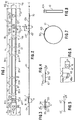
- reference numeral 10 generally designates a clamp structure which is provided with a so-called "Oetiker” ear generally designated by reference numeral 30 and a mechanical connection generally designated by reference numeral 40 (Figure 7).
- the clamping band 10 includes an inner band portion 10a and an outer band portion 10b which, in the installed condition mutually overlap, at least in part.
- the lateral band portions 10' and 10'' are bent down ( Figure 5) to impart elasticity to the clamping band by a more or less convex shape which seeks to flatten out as the clamp structure is tightened about the counterweight and rotating shaft.
- the lateral edges of the bent-down portions 10' and 10'' will seek to dig into the external surfaces of the rotating member (not shown) and of the counterweight. To enhance the anchoring, these edges may also be non-smooth as realized by any means described in my aforementioned British and U.S. Patents.
- the modified, plastically deformable ear generally designated by reference numeral 30 which serves as tightening means includes two generally outwardly extending leg portions 31 and 32 interconnected by a bridging portion 33 which is provided with a novel reinforcement arrangement ( Figures 2 and 3).
- the ear reinforcement arrangement is constituted by two groove-like reinforcing indentations 34 , each having a rounded-off bottom 35 , whereby each reinforcing groove is formed by substantially parallel, longitudinal side surfaces interconnected at each end by substantially semi-circularly shaped end portions as shown in Figures 1 and 3.
- the side surfaces as well as the end surfaces of a respective groove-like indentation 34 thereby slope down toward one another at an angle ⁇ with respect to the vertical, for example, at an angle of about 15° to merge into the rounded-off bottom.
- the mechanical connection generally designated by reference numeral 40 includes two cold-deformed, deep-drawn support hooks 41 which may be constructed as disclosed in my prior U.S. Patent 4,299,012 or as shown more particularly in Figures 1, 2 and 6 of this application.
- a novel guide and support hook 43 bent out of the clamping band about an axis extending generally in the longitudinal direction after two cuts as shown in greater detail in Figure 6.
- the combined guide and support hook 43 includes, in addition to the usual upwardly extending oblique guide surface 43' ( Figure 2) a forwardly extending tip with a slightly downwardly extending tip end portion 43'' to reliably prevent disengagement of the outer band portion 10b from the combined guide and support hook once the clamp structure is preassembled before tightening by engagement of the combined guide and support hook 43 in the slot-like aperture 44 in the outer band portion 10b .
- This particular configuration of the combined guide and support hook 43 is achieved by a first cut 43a and a subsequent part-circular second cut 43b which are made before the guide hook is bent out of the clamping band plane into its substantially vertical position.
- Rectangular, preferably square apertures 42 are provided in the outer band end portion 10b to receive the support hooks 41 as the two band end portions 10a and 10b are drawn toward one another by the surface 43' as the clamp is tightened by plastic deformation of the ear 30 .
- the counterweight generally designated by reference numeral 60 and shown in Figure 1 in dash-and-dotted lines, which may be of any suitable size and/or thickness, is secured to the inner clamping band portion 10a intermediate its free end and the first support hook 41 , for example, by welding schematically indicated at 70 .
- its corners 61 are bent down (not shown) so as to dig into the outer surface of the rotating member as the clamp structure is tightened.
- any of the anchoring arrangements disclosed in my aforementioned British and U.S. Patents may also be used.
- the counterweight of predetermined weight and size may be made of any known material suitable therefor, such as of lead and alloys thereof, powdered metals or even of a commercially available lead tape provided with an adhesive surface which would also enhance anchoring.
- a number of rectangular apertures 20a , 20b , 20c , 20d and 20e are provided, which are located in the area of the clamp structure at least approximately opposite the area of the mechanical connection and the counterweight.
- the size and number as well as the configurations of the apertures may be selected as desired for a particular application, depending also on the strength of the material for the clamp structure.
- a relatively longer aperture 20c is followed on each side by two or more smaller apertures 20a , 20b and 20d , 20e with each aperture of substantially rectangular configuration having rounded-off corners.
- the width dimension of the web portions 21 between adjacent apertures i.e., the dimension of these web portions 21 in the clamping band longitudinal direction, may again be chosen depending on the type of material used, for example, galvanized steel or stainless steel which have different strength properties. As a rule of thumb, the width of these web portions 21 should be at least about 20% to about 25% of the width of the clamping band.
- the circumferential area of the clamp structure covered by such apertures again depends on the strength of the material and can be empirically determined readily to optimize a given design. However, it follows that the greater this circumferential area, the greater will be the effect of the counterweight.
- Figure 9 illustrates a modified embodiment of a clamp structure for use in the balancing arrangement of this invention in which the rectangular apertures 20a , 20b , 20c , 20d and 20e of Figure 1 are replaced by circular apertures 120 which may extend over substantially the entire clamping band portion intermediate the inner and outer band end portions 10a and 10b because of greater strength of this arrangement.
- circular apertures 120 may extend over substantially the entire clamping band portion intermediate the inner and outer band end portions 10a and 10b because of greater strength of this arrangement.
- oval apertures and/or a combination of regularly or non-regularly following oval and circular apertures As to the rest, the embodiment of Figure 9 is similar to that of Figures 1 through 8.
- clamping band used in the various embodiments of this invention may also be provided with elasticity-enhancing sections having concavely shaped lateral band portions defining therebetween an approximately hourglass-shaped window, as disclosed in the aforementioned British patent or in U.S. Patent 5,230,246 .
- the clamping band 10 may be provided with one or preferably several sections 220 , each provided with a window 221 resembling the shape of an hourglass but retaining the substantially rectilinear outer edges 222a and 222b .
- the size, i.e., length and width as well as the curvature 223 of each section 220 and the width of the web portions 224 may be readily determined empirically to optimize the desired results in a given application, whereby the curvatures 223 are preferably part of a circular arc with a radius of curvature greater than one half, preferably two-thirds of the width of the clamping band.
- the window 221 also preferably has rounded-off corners 225 with a radius of curvature substantially smaller than the radius of curvature 223 .
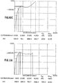
- Table I sets forth the test data obtained with three clamp samples having the reinforced ear structure according to my aforementioned U.S. Patent 5,326,325, while Figures 10A, 10B and 10C are graphs representing the test data obtained with the ear of the aforementioned patent.
- Table II shows the test data obtained with three clamp samples having an ear construction according to the embodiment of Figures 1 through 5, while Figures 11A, 11B and 11C again show graphically these test results.
- Figure 12 illustrates an improved low-profile, earless clamp structure for use in a balancing arrangement of this invention which has an improved mechanical connection, increases reliability in effecting the mechanical connection and is designed for easy and secure fastening of a counterweight.
- the clamping band generally designated by reference numeral 210 which is preferably made also of greater width like clamping band 10 , is again provided with lateral bent-down portions 210' and 210'' and includes an inner band end portion 210a and an outer band end portion 210b .
- an elongated aperture 221 is provided with rounded-off end portions to receive a corresponding knub-like pressed-out part in the counterweight (not shown) which fits into aperture 221 for centering purposes.
- the counterweight may be of any known construction as disclosed in connection with counterweight 60 of Figure 1.
- a tunnel-shaped member 231 pressed out by deep-drawing after two transverse cuts which forms part of the disconnecting means and is followed by a novel support hook 232 forming part of the mechanical connection and capable of absorbing higher circumferentially directed tightening forces in the completely tightened and installed condition of the clamp structure.
- the support hook 232 is again followed by a tunnel-shaped member 233 which forms part of the connecting means for tightening the reusable clamp structure.
- a number of apertures for example, circular apertures 220 alternating with oval apertures 220' , the number and arrangement of which may be varied as known to those skilled in the art.
- apertures as shown in Figure 1 or apertures as shown in Figure 19 may be used.
- elasticity-imparting sections as disclosed in my British patent or in my U.S.
- Patent 5,230,246 may be used, the location of such apertures and/or sections being preferably again at least within an area of the clamping band approximately opposite to the counterweight and/or mechanical connection and extending over a circumferential part of the clamping band which may include all but the clamping band end portions 210a and 210b .
- Another tunnel-shaped member 234 which serves as part of the disconnecting means is adjoined directly by a substantially rectangular opening 222 provided with a tongue-like preassembly projection 223 in the transverse surface nearer the free end of the outer band portion 210b which is adapted to engage with tunnel-shaped member 231 to provide a preassembly.
- the opening 222 which is of such width that the tunnel-shaped member 231 can extend into the same, is followed by a tunnel-shaped member 235 forming part of the tightening means for tightening the reusable clamp.
- a pressed-out reinforcement 250 surrounds at least partially the tunnel-shaped member 235 in the free end area of the outer clamping band end portion 210b which surprisingly prevents a lifting-up of the free end of the outer band end portion when tightening the clamp and also imparts greater stability to the tunnel-shaped member 235 .
- the tunnel-shaped member 231 is thereby of smaller configuration than tunnel-shaped member 234 so that it can slide under the latter, if necessary.
- a preferred embodiment of the front end reinforcement 250 is shown in Figures 16, 17 and 18 in which the reinforcement 250 extends not only transversely in front of tunnel-shaped member 235 with its transversely extending part 252 but also extends laterally of this tunnel-shaped member 235 in the longitudinal direction with its lateral parts 251 to thereby surround the tunnel-shaped member 235 in front thereof and along the sides thereof over at least nearly half the length.
- This reinforcement 250 effectively prevents the free end of the outer band end portion 210b from lifting up when the clamp is tightened by engagement of a pincer-like tool at tool-engaging surfaces 235 ' and 233 '.
- Figures 13, 14 and 15 illustrate the details of the novel support hook 232 of this invention which forms part of the mechanical connection and which is pressed out by deep-drawing after a cut limited substantially to the circular portion 232b'' ( Figure 15) to assume the configuration as illustrated in Figure 13 in which the substantially rectilinear ramp-like surface 232a slanting obliquely upwardly away from the free end of the inner band portion terminates in a substantially flat portion 232b forming a nose-like part 232c , by means of which, in the connected position, it engages from underneath in the opening of the tunnel-shaped member 235 in such a manner that the nose-like part 232c extends over and engages with the slanting guide surface 232d at the edge in the band end portion 10b formed by the transverse cut of the tunnel-shaped member 235 nearer the reinforcement 250 .
- the substantially rectilinear slanting surface 232a and its flat portion 232b thereby facilitate tightening of the clamp structure as the outer band end portion 210b reinforced by reinforcement 250 slidingly rides up this ramp-like surface 232a and passes over the flat portion 232b during tightening of the clamp structure until the nose-like part 232c is able to snap into the opening underneath the tunnel-shaped member 235 so that the surface 232d can now engage with the transverse edge of the clamping band caused by the transverse cut for the tunnel-shaped member nearer the reinforcement 250 .
- the flat portion 232b thereby improves the support hook 232 in several respects.
- the flat portion 232b greatly strengthens the hook 232 against buckling or collapsing as the outer band portion 210b slides up over the ramp-like surface 232a during tightening of the clamp, particularly as it reaches the upper end of this ramp-like surface.
- the flat portion 232b also facilitates the sliding movement of the outer band portions 210b during tightening of the clamp as it not only shortens the ramp-like surface 232a but facilitates this sliding movement by eliminating the inclined top portion of the ramp-like surface of prior support hooks and instead provides a flat surface which has a substantially constant radial distance in the installed clamp.
- the earless clamp structure of Figures 12 through 18 is thereby installed and disassembled in a conventional manner as known to those skilled in the art by utilizing a tool seeking to draw together from the preassembled condition the tunnel-shaped members 233 and 235 and by utilizing a tool seeking to draw together the members 231 and 234 for reopening the clamp structure.
- the embodiment of Figure 12 also illustrates cutouts 271' and 271'' in the inner band end portion for fastening the counterweight which may be provided with corresponding hook-like members cut out from the counterweight by substantially parallel cuts and bent-up so that they can extend through these cutouts 271' and 271'' and then be bent over to securely fasten the counterweight in the preassembled condition, whereby the knub-like projection engages in aperture 231 to hold the counterweight centered.
- Typical values for the various embodiments are as follows, it being understood that these values are typical merely for one given embodiment of the invention and are not to be construed as limitative in any way of possible embodiments of this invention which may be varied as known to those skilled in the art. All dimensions indicated hereinafter are in millimeters and are taken from the drawings attached to the provisional application.
- the length dimension a depends on the diametric dimension of the clamp and in this particular embodiment is about 334 mm. and represents the length of the clamp from the free end of the inner band portion 10a to the edge nearer the free end of the outer band portion of the second aperture 42 .
- the dimension b from this same edge of the second aperture 42 to the free end of the outer band portion 10b is about 21 mm.
- the width c of the clamping band is 14 mm. and the dimension d from the free end of the outer band portion 10b to the outwardly extending leg 31 of the plastically deformable ear 30 is about 34 mm.
- the apertures 42 are each about 5.5 mm. in the clamping band transverse direction and about 5 mm. in the longitudinal direction of the clamping band.
- the width of the slot-like aperture 44 in the transverse direction is about 2 mm., and its length in the longitudinal direction is about 6 mm.
- the spacing between mutually facing edges of the apertures 42 is about 3 mm.
- each groove-like indentation 34 is about 6 mm.
- the radius of curvature of the rounded-off bottom 35 of each groove-like indentation is about 1 mm.
- the spacing h between the centers of the bottoms of the groove-like indentation in the clamping band transverse direction is also about 6 mm.
- the angle ⁇ of the longitudinally extending lateral walls of each groove-like indentation which are inclined toward one another is about 15°.
- the leg portions 31 and 32 need not extend exactly at right angle to the surface of the clamping band but may form an angle of about 5° perpendicular to the clamping band surface ( Figure 2).
- the dimension i from the free end of the inner band portion 10a to the edge 41' of the support hook nearer the free end of the inner band portion is about 48.6 mm. and the spacing j from this edge 41' to the center of the part-circular cut 43b is about 10 mm. while the spacing between the center of cut 43b and the edge 41' of the support hook 41 remote from free end of the inner band portion 10a is about 10.2 mm.
- the diameter of the part-circular cut 43b is 2 mm.
- the distance k in the longitudinal direction from the center of cut 43b to the end of the cut 43a is about 4.7 mm. so that the distance 1 is 5.5 mm.
- the diameter of the cut 43b is about 2 mm. and the radii of curvature in the cut 43a are about 1 mm.
- the width m in the transverse direction of each support hook 41 is about 5 mm. and the distance n of the center of the circular aperture 70 from the free end of the inner band portion 10a is about 21 mm.
- the apertures 20a , 20b , 20d and 20e have an overall length p in the longitudinal direction of about 20 mm. and a width q of about 8 mm. with the corners rounded off with a radius of curvature of about 2 mm. in the four corners thereof.
- the length r in the longitudinal direction of the longer aperture 20c is about 60 mm. with a width again of about 8 mm.
- the angle of inclination ⁇ of the inclined lateral band portions within the area of aperture 20c is about 15° whereby the length of the remaining lateral band portions within the area of these apertures 20a through 20e is about 2 mm.
- the angle ⁇ ' may be about 20°.
- the dimension s is about 13.5 mm. and the dimension t about 8 mm.
- FIG. 9 is similar to the embodiment of Figures 1 through 8 except that the apertures 20a through 20e are replaced by regularly spaced openings 120 whose diameter can be selected at any desired value, depending on material to be used, and thickness of the clamping band material to enhance the effectiveness of the counterweight as mentioned above.
- the improved guide-and-support hook 232 has a width A ( Figure 15) of about 4.4 mm. and a length B of about 5 mm.
- the part-circular cut portion 232b'' is formed with a radius R of about 2.5 mm.
- the flattened portion 232b has a length C ( Figure 13) in the longitudinal direction of about 0.8 mm. with a height D of about 2.9 mm.
- the ramp-like inclined surface 232a forms an angle ⁇ of about 27.7° ( Figure 13).
- the centers of the radii of curvature for the radii R2 are spaced from one another in the transverse direction of the clamping band a distance E of about 4.38 mm.
- the width M ( Figure 16) in the longitudinal direction of the reinforcement 250 is 2 mm.
- the embossed pressed-out height N of the reinforcement ( Figure 17) obtained by deep-drawing is about 0.3 mm.
- the radii of curvature R4 ( Figure 17) are 1.82 mm.
- the radius of curvature R5 is 0.57 mm.
- the spacing P of the center line of transversely extending portion 252 of the reinforcement 250 to the free end of the outer band portion 210b is about 2.5 mm., and the dimension O from the free end of the outer band portion 210b to the center of the semi-circular end portion of the two lateral portions 251 of the reinforcement 250 is 5.5 mm. whereby the center of the rounded-off ends of the lateral portions 251 are spaced from one another in the transverse direction a distance Q of about 9 mm.
- the tool-engaging surface 235' is spaced from the free end of the outer band portion 210b by a distance S of about 9 mm.
- the height H of the tunnel-shaped member 235 ( Figure 18) is about 3.2 mm.
- the spacing T in the transverse direction of the clamping band by the centers of the radii of curvature for radii R6 is 5.8 mm.
- the radii of curvature R6 are about 0.5 mm.
- the radius of curvature R7 is 1.7 mm.
- the radius of curvature R8 is 1.1 mm.
- the other dimensions of the clamp structure of Figure 12 are readily ascertainable to a person skilled in the art from the design criteria used with earless clamp structures manufactured by and commercially available from the assignee of the instant application. It should also be noted that all dimensions are given in the flat condition of the clamping band.
- a counterweight of standard size may be used, for example, of rectangular configuration with the corners thereof chamfered off and all of the same dimensions which offer different weights by the number, size and locations of the openings 62 ( Figure 20) provided in the plate-like counterweight members 60 .
- the plate-like member without any openings may have a weight of 5 grams, and with two openings 62 as shown in Figure 20 may have a weight of 2 grams. Intermediate values can be attained by the number and size of such openings.
- the person selecting the required counterweight can then assemble the required weight from a number of such plate-like members.
- each plate-like member is provided with a small pressed-out knub-like indentation 61 ( Figures 20 and 21) which permits stacking the plate-like members in proper position and retaining the stacked plate-like members in such position.
- the required weight for the counterweight is less than the weight of the connection of the overlapping band portions and the tightening means, it may be desirable to provide a balancing clamp structure preassembled by means of a counterweight so as to balance the clamp structure in itself.
- the plate-like member representing the combined weight of the connecting and tightening means may be permanently secured, for example, by welding in the area opposite the connecting and tightening means whereby only one or several small plate-like members need to be selected to balance the rotating member by placing these plate-like members in the correct position on the rotating member.
- the plate-like member(s) to compensate for the imbalance in the rotating member may then be assembled in stacked relationship to the permanently secured balancing weight.
- This permits the use of a standard size of plate-like members though also more than one standard size of plate-like members may be used provided they also include the pressed-out knub-like indentations to permit stacking with plate-like members of different sizes.
- standard sizes of different thickness may also be provided as long as the plate-like members are always provided with the means to enable stacking thereof. This not only facilitates the work of the person charged with balancing the rotating member but also keeps the assembled plate-like members in predetermined relative position by preventing relative movement once in stacked relationship. If the stack of plate-like members would become too high in a radial direction as installed on the rotating member, it is only necessary to use two clamp structures side-by-side to divide the number of stacked plate-like members used with each clamp structure.
- auxiliary spring structure may also be incorporated in each of the various embodiments of the clamp structures described herein by utilizing the auxiliary spring arrangements as disclosed in my prior U.S. Patents 5,111,555 and 5,138,747 .
Landscapes
- Engineering & Computer Science (AREA)
- General Engineering & Computer Science (AREA)
- Mechanical Engineering (AREA)
- Clamps And Clips (AREA)
- Motor Power Transmission Devices (AREA)
- Tyre Moulding (AREA)
Applications Claiming Priority (2)
| Application Number | Priority Date | Filing Date | Title |
|---|---|---|---|
| US2076396P | 1996-06-28 | 1996-06-28 | |
| US20763P | 1996-06-28 |
Publications (3)
| Publication Number | Publication Date |
|---|---|
| EP0816739A2 true EP0816739A2 (fr) | 1998-01-07 |
| EP0816739A3 EP0816739A3 (fr) | 1999-10-06 |
| EP0816739B1 EP0816739B1 (fr) | 2006-05-03 |
Family
ID=21800429
Family Applications (1)
| Application Number | Title | Priority Date | Filing Date |
|---|---|---|---|
| EP97108941A Expired - Lifetime EP0816739B1 (fr) | 1996-06-28 | 1997-06-03 | Dispositif d'équilibrage amélioré pour arbres creux de transmission |
Country Status (8)
| Country | Link |
|---|---|
| EP (1) | EP0816739B1 (fr) |
| KR (1) | KR100511131B1 (fr) |
| CN (1) | CN1133105C (fr) |
| DE (1) | DE69735791T2 (fr) |
| ES (1) | ES2262164T3 (fr) |
| PT (1) | PT816739E (fr) |
| TW (1) | TW359654B (fr) |
| ZA (2) | ZA975107B (fr) |
Cited By (1)
| Publication number | Priority date | Publication date | Assignee | Title |
|---|---|---|---|---|
| US7937812B2 (en) | 2005-03-31 | 2011-05-10 | Nhk Spring Co., Ltd. | Boot band |
Families Citing this family (2)
| Publication number | Priority date | Publication date | Assignee | Title |
|---|---|---|---|---|
| CN101149306B (zh) * | 2007-10-26 | 2010-06-30 | 上海大学 | 自动配平装置 |
| DE102022108054A1 (de) * | 2022-04-04 | 2023-10-05 | Oetiker Schweiz Ag | Bandklemme mit rippe auf der innenfläche |
Citations (7)
| Publication number | Priority date | Publication date | Assignee | Title |
|---|---|---|---|---|
| US4724583A (en) * | 1985-05-23 | 1988-02-16 | Nhk Spring Co., Ltd. | Hose band |
| US4998326A (en) * | 1989-12-06 | 1991-03-12 | Hans Oetiker Ag Maschioen- Und Apparatefabrik | Balanced clamp structure |
| DE3930716C1 (fr) * | 1989-09-14 | 1991-04-18 | Rasmussen Gmbh, 6457 Maintal, De | |
| GB2238846A (en) * | 1989-12-06 | 1991-06-12 | Oetiker Hans Maschinen | Balancing arrangement for rotating member and method of making same |
| US5230246A (en) * | 1984-06-20 | 1993-07-27 | Hans Oetiker Ag Maschinen- Und Apparatefabrik | Balancing arrangement for rotating member |
| US5283931A (en) * | 1992-05-20 | 1994-02-08 | Hans Oetiker Ag Maschinen- Und Apparatefabrik | Reusable earless clamp structure |
| EP0601307A1 (fr) * | 1992-12-09 | 1994-06-15 | Hans Oetiker AG Maschinen- und Apparatefabrik | Collier de serrage pour l'équilibrage de membres tournants |
Family Cites Families (1)
| Publication number | Priority date | Publication date | Assignee | Title |
|---|---|---|---|---|
| US5537721A (en) * | 1994-08-19 | 1996-07-23 | Hans Oetiker Ag Maschinen- Und Apparatefabrik | Tolerance-compensating hose clamp |
-
1997
- 1997-06-03 EP EP97108941A patent/EP0816739B1/fr not_active Expired - Lifetime
- 1997-06-03 PT PT97108941T patent/PT816739E/pt unknown
- 1997-06-03 DE DE69735791T patent/DE69735791T2/de not_active Expired - Lifetime
- 1997-06-03 ES ES97108941T patent/ES2262164T3/es not_active Expired - Lifetime
- 1997-06-10 ZA ZA9705107A patent/ZA975107B/xx unknown
- 1997-06-10 ZA ZA9705108A patent/ZA975108B/xx unknown
- 1997-06-27 TW TW086109035A patent/TW359654B/zh not_active IP Right Cessation
- 1997-06-27 CN CN97113546A patent/CN1133105C/zh not_active Expired - Fee Related
- 1997-06-27 KR KR1019970027934A patent/KR100511131B1/ko not_active IP Right Cessation
Patent Citations (7)
| Publication number | Priority date | Publication date | Assignee | Title |
|---|---|---|---|---|
| US5230246A (en) * | 1984-06-20 | 1993-07-27 | Hans Oetiker Ag Maschinen- Und Apparatefabrik | Balancing arrangement for rotating member |
| US4724583A (en) * | 1985-05-23 | 1988-02-16 | Nhk Spring Co., Ltd. | Hose band |
| DE3930716C1 (fr) * | 1989-09-14 | 1991-04-18 | Rasmussen Gmbh, 6457 Maintal, De | |
| US4998326A (en) * | 1989-12-06 | 1991-03-12 | Hans Oetiker Ag Maschioen- Und Apparatefabrik | Balanced clamp structure |
| GB2238846A (en) * | 1989-12-06 | 1991-06-12 | Oetiker Hans Maschinen | Balancing arrangement for rotating member and method of making same |
| US5283931A (en) * | 1992-05-20 | 1994-02-08 | Hans Oetiker Ag Maschinen- Und Apparatefabrik | Reusable earless clamp structure |
| EP0601307A1 (fr) * | 1992-12-09 | 1994-06-15 | Hans Oetiker AG Maschinen- und Apparatefabrik | Collier de serrage pour l'équilibrage de membres tournants |
Cited By (1)
| Publication number | Priority date | Publication date | Assignee | Title |
|---|---|---|---|---|
| US7937812B2 (en) | 2005-03-31 | 2011-05-10 | Nhk Spring Co., Ltd. | Boot band |
Also Published As
| Publication number | Publication date |
|---|---|
| CN1170895A (zh) | 1998-01-21 |
| MX9704872A (es) | 1998-06-30 |
| KR980003133A (ko) | 1998-03-30 |
| EP0816739A3 (fr) | 1999-10-06 |
| PT816739E (pt) | 2006-06-30 |
| KR100511131B1 (ko) | 2005-10-25 |
| DE69735791D1 (de) | 2006-06-08 |
| EP0816739B1 (fr) | 2006-05-03 |
| TW359654B (en) | 1999-06-01 |
| DE69735791T2 (de) | 2006-12-28 |
| ES2262164T3 (es) | 2006-11-16 |
| ZA975108B (en) | 1997-12-31 |
| ZA975107B (en) | 1998-03-23 |
| CN1133105C (zh) | 2003-12-31 |
Similar Documents
| Publication | Publication Date | Title |
|---|---|---|
| EP1069363B1 (fr) | Connexion pour portions de bandes superposables de type à rivet | |
| CA1274069A (fr) | Collier de serrage pour tuyau souple | |
| CA2031314C (fr) | Dispositif de fixation compense | |
| US4712278A (en) | Earless clamp structure | |
| AU2006343202B2 (en) | Band clamp | |
| US5283931A (en) | Reusable earless clamp structure | |
| US5768751A (en) | Low profile earless clamp | |
| EP0499877A1 (fr) | Structure d'un collier de serrage à haute résistance | |
| US5138747A (en) | Clamp structure with improved spring action | |
| US6345551B1 (en) | Balancing arrangement for hollow drive shafts | |
| EP0816739A2 (fr) | Dispositif d'équilibrage amélioré pour arbres creux de transmission | |
| CA2055986C (fr) | Dispositif d'equilibrage pour element tournant | |
| EP1196712B1 (fr) | Raccord mecanique pour colliers de serrage ouverts | |
| CA2206923C (fr) | Dispositif d'equilibrage ameliore pour arbre creux d'entrainement | |
| GB2367871A (en) | Clamp | |
| EP0697555B1 (fr) | Collier de serrage réutilisable à compensation des tolérances | |
| MXPA97004872A (es) | Estructura de abrazadera sin oreja de bajo perfil |
Legal Events
| Date | Code | Title | Description |
|---|---|---|---|
| PUAI | Public reference made under article 153(3) epc to a published international application that has entered the european phase |
Free format text: ORIGINAL CODE: 0009012 |
|
| AK | Designated contracting states |
Kind code of ref document: A2 Designated state(s): BE CH DE ES FR GB IT LI NL PT SE |
|
| PUAL | Search report despatched |
Free format text: ORIGINAL CODE: 0009013 |
|
| AK | Designated contracting states |
Kind code of ref document: A3 Designated state(s): AT BE CH DE DK ES FI FR GB GR IE IT LI LU MC NL PT SE |
|
| RIC1 | Information provided on ipc code assigned before grant |
Free format text: 6F 16L 33/02 A, 6F 16F 15/34 B, 6B 65D 63/04 B |
|
| 17P | Request for examination filed |
Effective date: 19991201 |
|
| AKX | Designation fees paid |
Free format text: BE CH DE ES FR GB IT LI NL PT SE |
|
| 17Q | First examination report despatched |
Effective date: 20040629 |
|
| GRAP | Despatch of communication of intention to grant a patent |
Free format text: ORIGINAL CODE: EPIDOSNIGR1 |
|
| GRAS | Grant fee paid |
Free format text: ORIGINAL CODE: EPIDOSNIGR3 |
|
| GRAA | (expected) grant |
Free format text: ORIGINAL CODE: 0009210 |
|
| AK | Designated contracting states |
Kind code of ref document: B1 Designated state(s): BE CH DE ES FR GB IT LI NL PT SE |
|
| REG | Reference to a national code |
Ref country code: GB Ref legal event code: FG4D |
|
| REG | Reference to a national code |
Ref country code: SE Ref legal event code: TRGR |
|
| REG | Reference to a national code |
Ref country code: CH Ref legal event code: EP |
|
| REF | Corresponds to: |
Ref document number: 69735791 Country of ref document: DE Date of ref document: 20060608 Kind code of ref document: P |
|
| REG | Reference to a national code |
Ref country code: CH Ref legal event code: NV Representative=s name: FELBER & PARTNER AG PATENTANWAELTE |
|
| REG | Reference to a national code |
Ref country code: PT Ref legal event code: SC4A Effective date: 20060508 |
|
| REG | Reference to a national code |
Ref country code: ES Ref legal event code: FG2A Ref document number: 2262164 Country of ref document: ES Kind code of ref document: T3 |
|
| ET | Fr: translation filed | ||
| PLBE | No opposition filed within time limit |
Free format text: ORIGINAL CODE: 0009261 |
|
| STAA | Information on the status of an ep patent application or granted ep patent |
Free format text: STATUS: NO OPPOSITION FILED WITHIN TIME LIMIT |
|
| 26N | No opposition filed |
Effective date: 20070206 |
|
| PGFP | Annual fee paid to national office [announced via postgrant information from national office to epo] |
Ref country code: PT Payment date: 20100519 Year of fee payment: 14 Ref country code: FR Payment date: 20100709 Year of fee payment: 14 |
|
| PGFP | Annual fee paid to national office [announced via postgrant information from national office to epo] |
Ref country code: IT Payment date: 20100612 Year of fee payment: 14 |
|
| PGFP | Annual fee paid to national office [announced via postgrant information from national office to epo] |
Ref country code: NL Payment date: 20100603 Year of fee payment: 14 Ref country code: ES Payment date: 20100713 Year of fee payment: 14 Ref country code: CH Payment date: 20100617 Year of fee payment: 14 Ref country code: BE Payment date: 20100615 Year of fee payment: 14 |
|
| PGFP | Annual fee paid to national office [announced via postgrant information from national office to epo] |
Ref country code: SE Payment date: 20100617 Year of fee payment: 14 Ref country code: GB Payment date: 20100617 Year of fee payment: 14 Ref country code: DE Payment date: 20100824 Year of fee payment: 14 |
|
| REG | Reference to a national code |
Ref country code: PT Ref legal event code: MM4A Free format text: LAPSE DUE TO NON-PAYMENT OF FEES Effective date: 20111205 |
|
| BERE | Be: lapsed |
Owner name: HANS *OETIKER A.G. MASCHINEN- UND APPARATEFABRIK Effective date: 20110630 |
|
| REG | Reference to a national code |
Ref country code: NL Ref legal event code: V1 Effective date: 20120101 |
|
| PG25 | Lapsed in a contracting state [announced via postgrant information from national office to epo] |
Ref country code: PT Free format text: LAPSE BECAUSE OF NON-PAYMENT OF DUE FEES Effective date: 20111205 |
|
| REG | Reference to a national code |
Ref country code: CH Ref legal event code: PL |
|
| REG | Reference to a national code |
Ref country code: SE Ref legal event code: EUG |
|
| GBPC | Gb: european patent ceased through non-payment of renewal fee |
Effective date: 20110603 |
|
| PG25 | Lapsed in a contracting state [announced via postgrant information from national office to epo] |
Ref country code: IT Free format text: LAPSE BECAUSE OF NON-PAYMENT OF DUE FEES Effective date: 20110603 |
|
| REG | Reference to a national code |
Ref country code: FR Ref legal event code: ST Effective date: 20120229 |
|
| PG25 | Lapsed in a contracting state [announced via postgrant information from national office to epo] |
Ref country code: BE Free format text: LAPSE BECAUSE OF NON-PAYMENT OF DUE FEES Effective date: 20110630 |
|
| REG | Reference to a national code |
Ref country code: DE Ref legal event code: R119 Ref document number: 69735791 Country of ref document: DE Effective date: 20120103 |
|
| PG25 | Lapsed in a contracting state [announced via postgrant information from national office to epo] |
Ref country code: LI Free format text: LAPSE BECAUSE OF NON-PAYMENT OF DUE FEES Effective date: 20110630 Ref country code: CH Free format text: LAPSE BECAUSE OF NON-PAYMENT OF DUE FEES Effective date: 20110630 Ref country code: DE Free format text: LAPSE BECAUSE OF NON-PAYMENT OF DUE FEES Effective date: 20120103 Ref country code: FR Free format text: LAPSE BECAUSE OF NON-PAYMENT OF DUE FEES Effective date: 20110630 |
|
| PG25 | Lapsed in a contracting state [announced via postgrant information from national office to epo] |
Ref country code: NL Free format text: LAPSE BECAUSE OF NON-PAYMENT OF DUE FEES Effective date: 20120101 |
|
| PG25 | Lapsed in a contracting state [announced via postgrant information from national office to epo] |
Ref country code: GB Free format text: LAPSE BECAUSE OF NON-PAYMENT OF DUE FEES Effective date: 20110603 |
|
| PG25 | Lapsed in a contracting state [announced via postgrant information from national office to epo] |
Ref country code: SE Free format text: LAPSE BECAUSE OF NON-PAYMENT OF DUE FEES Effective date: 20110604 |
|
| REG | Reference to a national code |
Ref country code: ES Ref legal event code: FD2A Effective date: 20130605 |
|
| PG25 | Lapsed in a contracting state [announced via postgrant information from national office to epo] |
Ref country code: ES Free format text: LAPSE BECAUSE OF NON-PAYMENT OF DUE FEES Effective date: 20110604 |