EP0815534B1 - Setzen von blattzählern - Google Patents
Setzen von blattzählern Download PDFInfo
- Publication number
- EP0815534B1 EP0815534B1 EP96904194A EP96904194A EP0815534B1 EP 0815534 B1 EP0815534 B1 EP 0815534B1 EP 96904194 A EP96904194 A EP 96904194A EP 96904194 A EP96904194 A EP 96904194A EP 0815534 B1 EP0815534 B1 EP 0815534B1
- Authority
- EP
- European Patent Office
- Prior art keywords
- pressure
- port
- count
- sensed
- duct
- Prior art date
- Legal status (The legal status is an assumption and is not a legal conclusion. Google has not performed a legal analysis and makes no representation as to the accuracy of the status listed.)
- Expired - Lifetime
Links
Images


Classifications
-
- G—PHYSICS
- G06—COMPUTING OR CALCULATING; COUNTING
- G06M—COUNTING MECHANISMS; COUNTING OF OBJECTS NOT OTHERWISE PROVIDED FOR
- G06M1/00—Design features of general application
- G06M1/08—Design features of general application for actuating the drive
- G06M1/12—Design features of general application for actuating the drive by fluid means
- G06M1/123—Design features of general application for actuating the drive by fluid means by pneumatic means
-
- G—PHYSICS
- G06—COMPUTING OR CALCULATING; COUNTING
- G06M—COUNTING MECHANISMS; COUNTING OF OBJECTS NOT OTHERWISE PROVIDED FOR
- G06M9/00—Counting of objects in a stack thereof
- G06M9/02—Counting of objects in a stack thereof by using a rotating separator incorporating pneumatic suction nozzles
Definitions
- This invention relates to a method of setting-up a sheet counter, intended in particular - but not exclusively - for counting sheets of paper.
- a known form of sheet counter primarily intended for counting sheets of paper such as bank-notes, has an elongate element which is inserted into the corner region of a stack of paper sheets, the element having on one side a port which is connected back to a low (sub-atmospheric) pressure source.
- An elongate member having its axis substantially parallel to that of the element orbits around the latter and serves to transfer the corner regions of sheets, one at a time, from one side of the element to the other.
- the corner region of the next-to-be-counted sheet of paper in the stack is lifted from the stack by air drawn through the port until that sheet rests on that element and closes off the port.
- the element is moved through an acute angle to open a gap for the elongate member, orbiting round the element, to pass between that sheet and the remainder of the stack and then to transfer that sheet to the other side of the element.
- a pressure sensor is disposed to sense the pressure in the duct leading to the port, as close as possible to that port in order to allow the generation of a count signal.
- the pressure in the duct falls significantly below atmospheric pressure, and that pressure fall is detected and used to produce a count signal.
- the count signal resulting from the sensing of the pressure is combined with a position signal, so that a valid count will be generated only if a pressure change is detected at the time a sheet should close the suction port.
- EP-A-0 616 300 there is described a sheet counter of a generally similar kind to that described above and which dynamically can adjust a counting threshold as a counting operation proceeds. Specifically, it suggests that the count threshold should be dynamically set as a proportion of a rolling average of a predetermined number of vacuum levels obtained on previous count cycles. This method has the disadvantage that a counting operation must be commenced before an accurate threshold can be set up, by which time there might already have been one or more miscounts.
- a method of setting-up a sheet counter before the commencement of a counting operation which counter includes an element having a suction port over which the sheets to be counted are caused to lie in sequence one after another, a source of sub-atmospheric pressure connected by a duct to the port, and means to sense the pressure within the duct in the vicinity of the port which sensing means provides an electrical signal indicative of sensed pressure, in which method the port is left open and the pressure in the duct is sensed to obtain a first pressure, either before said source is operated to draw air through the port or after operation of said source has commenced; the source is operated and the port in the element is covered whereafter the pressure in the duct is sensed again to obtain a second pressure; and a count pressure value part-way between the first and second pressures is computed, a valid count signal in a subsequent counting operation being generated only if the instantaneous sensed pressure falls below the count pressure value.
- a count pressure threshold is established, so that a count signal may reliably be generated whenever the suction port is closed off, and no count signal will be generated whenever the suction port is open.
- This arrangement isolates the counting of the sheets from variations in the pressure of the low pressure source (which is usually a vacuum pump), such as may be caused by the performance of the source, and also from variations in atmospheric pressure.
- the first pressure may be sensed either with the low pressure source operating or before operation of the source has commenced.
- the currently-preferred technique is to commence operation of the source only after the first pressure sensing step has been completed, but as a matter of practice, both systems are possible and may be accommodated by a suitable adjustment in the subsequent computing step of the count pressure value.
- pressure in the duct is sampled a predetermined number of times over a pre-set time period, both when the port is open and when the port is covered. Then, the average of the sampled pressures may be used, in each case, as the open (first) and covered (second) pressures for the computing of the count pressure value.
- the low pressure source comprises a vacuum pump
- the low pressure source comprises a vacuum pump
- a filter on the up-stream side of the pump, to protect the pump from paper dust or other detritus which may enter the port. Should that filter become significantly clogged, then the performance of the vacuum pump may fall to such an extent that a reliable count cannot be achieved.
- the method of the present invention thus preferably includes a step of checking the difference between the open (first) and covered (second) pressures, and indicating an error condition if that pressure difference is below a predetermined value.
- the error condition may serve to inhibit further operation of the counter.
- the method of this invention may be performed on an automatic basis, immediately before the commencement of a counting operation, each time a counting operation is to be performed. It is thus convenient for the element having the port through which air is drawn to be positioned adjacent one end of a stack of sheets to be counted, but with the port still clear of that stack, so that the open pressure may be determined, the element then being moved into contact with the end sheet of the stack so as to cover the port, whereafter the covered pressure is determined. The sensing of the covered pressure may be inhibited for a pre-set period following the covering of the port, in order to allow the establishment of a substantially static covered pressure value.
- the method of this invention is performed by a micro-processor incorporated within the sheet counter, to fulfil the various functional requirements of that counter.
- the pressure sensor provides an analogue output indicative of sensed pressure
- that output may be converted to a digital signal for appropriate processing within the micro-processor.
- the sheet counter is of the design described above, and so has an elongate element for insertion in the corner region of a stack of sheets to be counted, and an elongate member arranged to lie substantially parallel to said element and which member is arranged to orbit around the element.
- the element has the suction port in the side thereof to which sheets are drawn, before being transferred to the other side of that element by the orbiting member.
- a sensor for the position of the elongate member which orbits around the element may be provided, so as to give an output at the time a count signal may be expected, which output is combined with the output from the pressure sensor so as further to minimise the likelihood of an erroneous count.
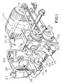
- Figure 1 shows a known form of sheet counter comprising a frame 10 which supports an electric motor 11 drivingly connected by means of toothed belts 12 and 13 to two cranks arranged one on each side of the frame, respectively.
- crank 14 is connected by a complex linkage 16A, 16B, 16C to a pivoted arm 17 which supports an elongate element in the form of a blade 18, in which is provided a suction port 19.
- the second crank is connected by a further complex linkage 20A, 20B, 20C to another arm 21 which is itself mounted on a third crank (not shown) driven by pulley 15 through meshing gears 22 and 23.
- Arm 21 carries an elongate member in the form of a rotatable pin 24 the axis of which is parallel to that of the blade 18. The mounting of the pin 24 in arm 21 allows the pin freely to rotate about its axis.
- a pressure sensor 27 is arranged to sense the pressure in a duct (not shown) within the frame 10, which connects port 19 to pipe 26.
- the sensor 27 provides an analogue electrical signal indicative of the instantaneous detected pressure.
- the modified counter includes a micro-processor to control the operation of the counter and to provide various required outputs and indications to an operator. That micro-processor may also be programmed to perform the setting-up method, on an automatic basis, each time a counting operation is to be performed.
- the micro-processor may include an internal analogue-to-digital converter which directly receives the analogue signal from the pressure sensor 27, or the analogue signal from the sensor 27 may be provided to a separate analogue-to-digital converter, the output of which is supplied to the micro-processor. Either way, the subsequent processing of the sensed pressures is performed digitally.
- Figure 3 is a flow chart showing the setting-up procedure which is to be performed automatically, immediately before a counting operation.
- the micro-processor causes the vacuum pump to start operating (step 30) and suspends other operations for a short predetermined time, in order to allow the pressure to stabilise.
- the signal from the pressure sensor 27 is sampled several times over a fixed time period (step 31), the average of those samples is determined and stored (step 32), this average being the port open pressure or low vacuum level.
- 16 samples may be made over 20 ms.
- a carrier (not shown) supporting the frame 10 and all the components mounted thereon is then moved to bring the blade 18 into contact with the bottom sheet of the stack of paper to be counted (step 33) and following a further short time delay to allow the pressure to stabilise, further samples of the sensed pressure are taken (step 34) over a fixed time period.
- a similar number of samples, taken over the same time period, may be performed here as in step 32. Again, the samples are averaged and stored (step 35) in order to obtain a port covered pressure or high vacuum level.
- a check (step 36) is then made on the difference between the open and covered pressures and provided that this pressure difference is sufficiently large, then a threshold point between the two pressures is calculated (step 37) in order to set a level at which a sheet is determined as being present on the blade 18 and covering the port 19, for transfer and so counting.
- the threshold point is set at approximately midway between the port open pressure and the port covered pressure, but advantageous results are obtained when the threshold is set at substantially 40% of the pressure difference, from the port open pressure.
- the pressure difference is not sufficiently large, an error condition is reported in step 36 and no further operation of the counter is permitted until the cause of the low pressure difference is corrected.
- the automatic setting-up procedure described above is carried out at the start of each count cycle, in order to accommodate any system variations.
- the procedure could however be operated less frequently, especially if the counter is used heavily - for example, it could be used only if the counter has been idle for some pre-set period, with the vacuum pump turned off.
- Use of the procedure also renders insignificant variations in atmospheric pressure, whether caused by climatic changes or in the physical location of the counter equipment.
- step 30 may take place only after the completion of step 31, the slightly different value then being obtained in step 32 being accommodated by a suitable adjustment in step 37.
Landscapes
- Physics & Mathematics (AREA)
- General Physics & Mathematics (AREA)
- Engineering & Computer Science (AREA)
- Theoretical Computer Science (AREA)
- Controlling Sheets Or Webs (AREA)
- Measuring Fluid Pressure (AREA)
- Examining Or Testing Airtightness (AREA)
Claims (10)
- Verfahren zum Setzen eines Bogenzählers vor dem Beginn eines Zählvorgangs, wobei der Zähler ein Bauteil mit einer Ansaugöffnung, bei der bewirkt wird, daß die zu zählenden Bögen der Reihe nach einer nach dem anderen über der Ansaugöffnung liegen, eine Unterdruckquelle, die mittels einer Leitung mit der Öffnung verbunden ist, und eine Einrichtung aufweist, um den Druck in der Leitung in der Nähe der Öffnung zu erfassen, wobei die Erfassungseinrichtung ein elektrisches Signal liefert, durch das der erfaßte Druck angegeben wird, wobei bei dem Verfahren die Öffnung offen gelassen und der Druck in der Leitung erfaßt wird, um einen ersten Druck zu erhalten, entweder bevor die Quelle betrieben wird, um Luft durch die Öffnung anzusaugen, oder nachdem der Betrieb der Quelle begonnen hat; die Quelle betrieben und die Öffnung in dem Bauteil verdeckt wird, wonach der Druck in der Leitung noch einmal erfaßt wird, um einen zweiten Druck zu erhalten; und ein Zähldruckwert zwischen dem ersten und zweiten Druck bestimmt wird, wobei ein gültiges Zählsignal in einem nachfolgenden Zählvorgang nur dann erzeugt wird, wenn der unmittelbar erfaßte Druck unter den Zähldruckwert fällt.
- Verfahren nach Anspruch 1, bei dem der Druck in der Leitung eine bestimmte Anzahl von Malen während einer voreingestellten Zeitdauer erfaßt wird, und zwar sowohl bei offener Öffnung als auch bei geschlossener Öffnung.
- Verfahren nach Anspruch 2, bei dem der Durchschnittswert der erfaßten Drücke in jedem Fall als der erste und zweite Druck für die Berechnung des Zähldruckwertes verwendet werden.
- Verfahren nach einem der vorhergehenden Ansprüche, das den Schritt umfaßt, die Differenz zwischen dem ersten und zweiten Druck zu erfassen und einen Fehlerzustand anzugeben, wenn die Druckdifferenz unterhalb eines vorbestimmten Wertes liegt.
- Verfahren nach Anspruch 4, bei dem ein weiterer Betrieb des Zählers verhindert wird, wenn die Druckdifferenz unterhalb des vorbestimmten Wertes liegt.
- Verfahren nach einem der vorhergehenden Ansprüche, das ausgestaltet ist, um die Anzahl von Bögen in einem Stapel zu zählen, wobei das Bauteil benachbart zu einem Ende des Stapels angeordnet wird, der erste Druck bestimmt wird und das Bauteil in Kontakt mit dem Endbogen des Stapels bewegt wird, um so die Öffnung zu verdecken, woraufhin der zweite Druck bestimmt wird.
- Verfahren nach Anspruch 6, bei dem das Erfassen des zweiten Druckes für eine bestimmte Zeitdauer nach dem Verdecken der Öffnung verzögert wird.
- Verfahren nach einem der vorhergehenden Ansprüche, bei dem der Sensor ein analoges Signal liefert, das den erfaßten Druck angibt, wobei das analoge Signal in ein digitales Signal umgewandelt und die Verarbeitung der erfaßten Werte digital durchgeführt wird.
- Verfahren nach einem der vorhergehenden Ansprüche, bei dem das Verfahren automatisch unmittelbar vor dem Beginn eines Zählvorgangs durchgeführt wird, und zwar jedes Mal wenn ein Zählvorgang durchgeführt werden soll.
- Verfahren nach einem der vorhergehenden Ansprüche, bei dem der Zähldruckwert bei im wesentlichen 40 % der Differenz zwischen dem ersten und zweiten Druck von dem ersten Druck eingestellt wird.
Applications Claiming Priority (3)
| Application Number | Priority Date | Filing Date | Title |
|---|---|---|---|
| GBGB9504357.6A GB9504357D0 (en) | 1995-03-03 | 1995-03-03 | Setting-up sheet counters |
| GB9504357 | 1995-03-03 | ||
| PCT/GB1996/000454 WO1996027856A1 (en) | 1995-03-03 | 1996-03-01 | Setting-up sheet counters |
Publications (2)
| Publication Number | Publication Date |
|---|---|
| EP0815534A1 EP0815534A1 (de) | 1998-01-07 |
| EP0815534B1 true EP0815534B1 (de) | 1998-10-07 |
Family
ID=10770634
Family Applications (1)
| Application Number | Title | Priority Date | Filing Date |
|---|---|---|---|
| EP96904194A Expired - Lifetime EP0815534B1 (de) | 1995-03-03 | 1996-03-01 | Setzen von blattzählern |
Country Status (6)
| Country | Link |
|---|---|
| US (1) | US5859889A (de) |
| EP (1) | EP0815534B1 (de) |
| JP (1) | JPH11501742A (de) |
| DE (1) | DE69600764T2 (de) |
| GB (1) | GB9504357D0 (de) |
| WO (1) | WO1996027856A1 (de) |
Families Citing this family (1)
| Publication number | Priority date | Publication date | Assignee | Title |
|---|---|---|---|---|
| USD447969S1 (en) | 2000-05-15 | 2001-09-18 | Smc Kabushiki Kaisha | Pressure detecting sensor |
Family Cites Families (4)
| Publication number | Priority date | Publication date | Assignee | Title |
|---|---|---|---|---|
| CH683878A5 (fr) * | 1989-11-10 | 1994-05-31 | Laurel Bank Machine Co | Machines à compter des feuilles. |
| JPH0594569A (ja) * | 1991-03-05 | 1993-04-16 | Laurel Bank Mach Co Ltd | 紙幣計数機における磁気検出回路の自動調整装置 |
| GB9303222D0 (en) * | 1993-02-18 | 1993-04-07 | Rue De Systems Ltd | Provements relating to sheet processing |
| GB9312614D0 (en) * | 1993-06-18 | 1993-08-04 | Portals Eng Ltd | Sheet counting |
-
1995
- 1995-03-03 GB GBGB9504357.6A patent/GB9504357D0/en active Pending
-
1996
- 1996-03-01 US US08/894,968 patent/US5859889A/en not_active Expired - Fee Related
- 1996-03-01 WO PCT/GB1996/000454 patent/WO1996027856A1/en not_active Ceased
- 1996-03-01 JP JP8526678A patent/JPH11501742A/ja not_active Ceased
- 1996-03-01 EP EP96904194A patent/EP0815534B1/de not_active Expired - Lifetime
- 1996-03-01 DE DE69600764T patent/DE69600764T2/de not_active Expired - Fee Related
Also Published As
| Publication number | Publication date |
|---|---|
| DE69600764D1 (de) | 1998-11-12 |
| EP0815534A1 (de) | 1998-01-07 |
| JPH11501742A (ja) | 1999-02-09 |
| GB9504357D0 (en) | 1995-04-26 |
| US5859889A (en) | 1999-01-12 |
| DE69600764T2 (de) | 1999-05-06 |
| WO1996027856A1 (en) | 1996-09-12 |
Similar Documents
| Publication | Publication Date | Title |
|---|---|---|
| US5450883A (en) | System and method for testing for error conditions in a fuel vapor recovery system | |
| US4072934A (en) | Method and apparatus for detecting a blockage in a vapor flow line | |
| JP3816561B2 (ja) | 取引端末機 | |
| EP0521625A1 (de) | Vorrichtung zum Testen der Steifheit eines Blattes | |
| US5859889A (en) | Setting-up sheet counters | |
| CA2231213A1 (en) | Mailing machine including dimensional rating capability | |
| EP1162360A3 (de) | Vorrichtung zur Erkennung einer Fehlfunktion eines Verbrennungsmotors | |
| GB2123178A (en) | Splice-in-register control | |
| EP0665126B1 (de) | Verfahren und Vorrichtung zum Nachweis von Mangel/Überschuss an Artikel in einer Kuvertier- und Verschliessmaschine | |
| JP2825811B2 (ja) | アッセンブリ・マシーンにおける印刷シートの制御方法 | |
| US6308951B1 (en) | Device for detecting a sheet stack height in a tray | |
| GB2087754A (en) | An indicator for indicating the level of filling of a dust bag | |
| EP0942394B1 (de) | Zählen von gestapelten Blättern | |
| GB2298504A (en) | Sheet counter | |
| JPH0534055Y2 (de) | ||
| US6530525B1 (en) | Sheet counting apparatus and method | |
| JPS6228056B2 (de) | ||
| JPH1191955A (ja) | 紙葉類取出し装置 | |
| JPS6343566Y2 (de) | ||
| JP2540371B2 (ja) | 紙移動モニタ | |
| JPH0248935Y2 (de) | ||
| JP3373642B2 (ja) | ダスト放射線モニタ | |
| JP2533812Y2 (ja) | 紙葉類計数機 | |
| US5709378A (en) | Mechanism for counting stacked sheets | |
| JPH07253317A (ja) | 回転角度読取装置 |
Legal Events
| Date | Code | Title | Description |
|---|---|---|---|
| PUAI | Public reference made under article 153(3) epc to a published international application that has entered the european phase |
Free format text: ORIGINAL CODE: 0009012 |
|
| 17P | Request for examination filed |
Effective date: 19970924 |
|
| AK | Designated contracting states |
Kind code of ref document: A1 Designated state(s): DE ES FR GB IT NL |
|
| GRAG | Despatch of communication of intention to grant |
Free format text: ORIGINAL CODE: EPIDOS AGRA |
|
| 17Q | First examination report despatched |
Effective date: 19980127 |
|
| GRAG | Despatch of communication of intention to grant |
Free format text: ORIGINAL CODE: EPIDOS AGRA |
|
| GRAH | Despatch of communication of intention to grant a patent |
Free format text: ORIGINAL CODE: EPIDOS IGRA |
|
| GRAH | Despatch of communication of intention to grant a patent |
Free format text: ORIGINAL CODE: EPIDOS IGRA |
|
| GRAA | (expected) grant |
Free format text: ORIGINAL CODE: 0009210 |
|
| AK | Designated contracting states |
Kind code of ref document: B1 Designated state(s): DE ES FR GB IT NL |
|
| PG25 | Lapsed in a contracting state [announced via postgrant information from national office to epo] |
Ref country code: NL Free format text: LAPSE BECAUSE OF FAILURE TO SUBMIT A TRANSLATION OF THE DESCRIPTION OR TO PAY THE FEE WITHIN THE PRESCRIBED TIME-LIMIT Effective date: 19981007 Ref country code: IT Free format text: LAPSE BECAUSE OF FAILURE TO SUBMIT A TRANSLATION OF THE DESCRIPTION OR TO PAY THE FEE WITHIN THE PRESCRIBED TIME-LIMIT;WARNING: LAPSES OF ITALIAN PATENTS WITH EFFECTIVE DATE BEFORE 2007 MAY HAVE OCCURRED AT ANY TIME BEFORE 2007. THE CORRECT EFFECTIVE DATE MAY BE DIFFERENT FROM THE ONE RECORDED. Effective date: 19981007 Ref country code: ES Free format text: THE PATENT HAS BEEN ANNULLED BY A DECISION OF A NATIONAL AUTHORITY Effective date: 19981007 |
|
| REF | Corresponds to: |
Ref document number: 69600764 Country of ref document: DE Date of ref document: 19981112 |
|
| ET | Fr: translation filed | ||
| NLV1 | Nl: lapsed or annulled due to failure to fulfill the requirements of art. 29p and 29m of the patents act | ||
| PLBE | No opposition filed within time limit |
Free format text: ORIGINAL CODE: 0009261 |
|
| STAA | Information on the status of an ep patent application or granted ep patent |
Free format text: STATUS: NO OPPOSITION FILED WITHIN TIME LIMIT |
|
| 26N | No opposition filed | ||
| REG | Reference to a national code |
Ref country code: GB Ref legal event code: IF02 |
|
| PGFP | Annual fee paid to national office [announced via postgrant information from national office to epo] |
Ref country code: FR Payment date: 20040331 Year of fee payment: 9 |
|
| PGFP | Annual fee paid to national office [announced via postgrant information from national office to epo] |
Ref country code: GB Payment date: 20050301 Year of fee payment: 10 |
|
| PGFP | Annual fee paid to national office [announced via postgrant information from national office to epo] |
Ref country code: DE Payment date: 20050520 Year of fee payment: 10 |
|
| PG25 | Lapsed in a contracting state [announced via postgrant information from national office to epo] |
Ref country code: FR Free format text: LAPSE BECAUSE OF NON-PAYMENT OF DUE FEES Effective date: 20051130 |
|
| REG | Reference to a national code |
Ref country code: FR Ref legal event code: ST Effective date: 20051130 |
|
| PG25 | Lapsed in a contracting state [announced via postgrant information from national office to epo] |
Ref country code: GB Free format text: LAPSE BECAUSE OF NON-PAYMENT OF DUE FEES Effective date: 20060301 |
|
| PG25 | Lapsed in a contracting state [announced via postgrant information from national office to epo] |
Ref country code: DE Free format text: LAPSE BECAUSE OF NON-PAYMENT OF DUE FEES Effective date: 20061003 |
|
| GBPC | Gb: european patent ceased through non-payment of renewal fee |
Effective date: 20060301 |