EP0813459B1 - Drilling tool - Google Patents
Drilling tool Download PDFInfo
- Publication number
- EP0813459B1 EP0813459B1 EP96904056A EP96904056A EP0813459B1 EP 0813459 B1 EP0813459 B1 EP 0813459B1 EP 96904056 A EP96904056 A EP 96904056A EP 96904056 A EP96904056 A EP 96904056A EP 0813459 B1 EP0813459 B1 EP 0813459B1
- Authority
- EP
- European Patent Office
- Prior art keywords
- drilling tool
- tip
- cutting edges
- base body
- drill
- Prior art date
- Legal status (The legal status is an assumption and is not a legal conclusion. Google has not performed a legal analysis and makes no representation as to the accuracy of the status listed.)
- Expired - Lifetime
Links
Images


Classifications
-
- B—PERFORMING OPERATIONS; TRANSPORTING
- B23—MACHINE TOOLS; METAL-WORKING NOT OTHERWISE PROVIDED FOR
- B23B—TURNING; BORING
- B23B31/00—Chucks; Expansion mandrels; Adaptations thereof for remote control
- B23B31/008—Chucks; Expansion mandrels; Adaptations thereof for remote control with arrangements for transmitting torque
-
- B—PERFORMING OPERATIONS; TRANSPORTING
- B23—MACHINE TOOLS; METAL-WORKING NOT OTHERWISE PROVIDED FOR
- B23B—TURNING; BORING
- B23B51/00—Tools for drilling machines
-
- B—PERFORMING OPERATIONS; TRANSPORTING
- B23—MACHINE TOOLS; METAL-WORKING NOT OTHERWISE PROVIDED FOR
- B23B—TURNING; BORING
- B23B51/00—Tools for drilling machines
- B23B51/02—Twist drills
-
- B—PERFORMING OPERATIONS; TRANSPORTING
- B23—MACHINE TOOLS; METAL-WORKING NOT OTHERWISE PROVIDED FOR
- B23B—TURNING; BORING
- B23B2228/00—Properties of materials of tools or workpieces, materials of tools or workpieces applied in a specific manner
- B23B2228/16—Shape memory alloys
-
- B—PERFORMING OPERATIONS; TRANSPORTING
- B23—MACHINE TOOLS; METAL-WORKING NOT OTHERWISE PROVIDED FOR
- B23B—TURNING; BORING
- B23B2251/00—Details of tools for drilling machines
- B23B2251/02—Connections between shanks and removable cutting heads
-
- B—PERFORMING OPERATIONS; TRANSPORTING
- B23—MACHINE TOOLS; METAL-WORKING NOT OTHERWISE PROVIDED FOR
- B23B—TURNING; BORING
- B23B2251/00—Details of tools for drilling machines
- B23B2251/18—Configuration of the drill point
-
- B—PERFORMING OPERATIONS; TRANSPORTING
- B23—MACHINE TOOLS; METAL-WORKING NOT OTHERWISE PROVIDED FOR
- B23B—TURNING; BORING
- B23B2251/00—Details of tools for drilling machines
- B23B2251/48—Chip breakers
-
- Y—GENERAL TAGGING OF NEW TECHNOLOGICAL DEVELOPMENTS; GENERAL TAGGING OF CROSS-SECTIONAL TECHNOLOGIES SPANNING OVER SEVERAL SECTIONS OF THE IPC; TECHNICAL SUBJECTS COVERED BY FORMER USPC CROSS-REFERENCE ART COLLECTIONS [XRACs] AND DIGESTS
- Y10—TECHNICAL SUBJECTS COVERED BY FORMER USPC
- Y10S—TECHNICAL SUBJECTS COVERED BY FORMER USPC CROSS-REFERENCE ART COLLECTIONS [XRACs] AND DIGESTS
- Y10S408/00—Cutting by use of rotating axially moving tool
- Y10S408/713—Tool having detachable cutting edge
-
- Y—GENERAL TAGGING OF NEW TECHNOLOGICAL DEVELOPMENTS; GENERAL TAGGING OF CROSS-SECTIONAL TECHNOLOGIES SPANNING OVER SEVERAL SECTIONS OF THE IPC; TECHNICAL SUBJECTS COVERED BY FORMER USPC CROSS-REFERENCE ART COLLECTIONS [XRACs] AND DIGESTS
- Y10—TECHNICAL SUBJECTS COVERED BY FORMER USPC
- Y10T—TECHNICAL SUBJECTS COVERED BY FORMER US CLASSIFICATION
- Y10T408/00—Cutting by use of rotating axially moving tool
- Y10T408/44—Cutting by use of rotating axially moving tool with means to apply transient, fluent medium to work or product
- Y10T408/45—Cutting by use of rotating axially moving tool with means to apply transient, fluent medium to work or product including Tool with duct
- Y10T408/455—Conducting channel extending to end of Tool
-
- Y—GENERAL TAGGING OF NEW TECHNOLOGICAL DEVELOPMENTS; GENERAL TAGGING OF CROSS-SECTIONAL TECHNOLOGIES SPANNING OVER SEVERAL SECTIONS OF THE IPC; TECHNICAL SUBJECTS COVERED BY FORMER USPC CROSS-REFERENCE ART COLLECTIONS [XRACs] AND DIGESTS
- Y10—TECHNICAL SUBJECTS COVERED BY FORMER USPC
- Y10T—TECHNICAL SUBJECTS COVERED BY FORMER US CLASSIFICATION
- Y10T408/00—Cutting by use of rotating axially moving tool
- Y10T408/81—Tool having crystalline cutting edge
-
- Y—GENERAL TAGGING OF NEW TECHNOLOGICAL DEVELOPMENTS; GENERAL TAGGING OF CROSS-SECTIONAL TECHNOLOGIES SPANNING OVER SEVERAL SECTIONS OF THE IPC; TECHNICAL SUBJECTS COVERED BY FORMER USPC CROSS-REFERENCE ART COLLECTIONS [XRACs] AND DIGESTS
- Y10—TECHNICAL SUBJECTS COVERED BY FORMER USPC
- Y10T—TECHNICAL SUBJECTS COVERED BY FORMER US CLASSIFICATION
- Y10T408/00—Cutting by use of rotating axially moving tool
- Y10T408/89—Tool or Tool with support
- Y10T408/907—Tool or Tool with support including detailed shank
-
- Y—GENERAL TAGGING OF NEW TECHNOLOGICAL DEVELOPMENTS; GENERAL TAGGING OF CROSS-SECTIONAL TECHNOLOGIES SPANNING OVER SEVERAL SECTIONS OF THE IPC; TECHNICAL SUBJECTS COVERED BY FORMER USPC CROSS-REFERENCE ART COLLECTIONS [XRACs] AND DIGESTS
- Y10—TECHNICAL SUBJECTS COVERED BY FORMER USPC
- Y10T—TECHNICAL SUBJECTS COVERED BY FORMER US CLASSIFICATION
- Y10T408/00—Cutting by use of rotating axially moving tool
- Y10T408/89—Tool or Tool with support
- Y10T408/909—Having peripherally spaced cutting edges
- Y10T408/9095—Having peripherally spaced cutting edges with axially extending relief channel
- Y10T408/9097—Spiral channel
-
- Y—GENERAL TAGGING OF NEW TECHNOLOGICAL DEVELOPMENTS; GENERAL TAGGING OF CROSS-SECTIONAL TECHNOLOGIES SPANNING OVER SEVERAL SECTIONS OF THE IPC; TECHNICAL SUBJECTS COVERED BY FORMER USPC CROSS-REFERENCE ART COLLECTIONS [XRACs] AND DIGESTS
- Y10—TECHNICAL SUBJECTS COVERED BY FORMER USPC
- Y10T—TECHNICAL SUBJECTS COVERED BY FORMER US CLASSIFICATION
- Y10T408/00—Cutting by use of rotating axially moving tool
- Y10T408/89—Tool or Tool with support
- Y10T408/909—Having peripherally spaced cutting edges
- Y10T408/9098—Having peripherally spaced cutting edges with means to retain Tool to support
- Y10T408/90993—Screw driven means
Definitions
- the invention relates to a drilling tool with a drill tip, the two approximately main cutting edges having equal circumferential distances from one another and two rake faces and main open faces adjacent to the main cutting edges has, optionally with an axially connected to the drill tip designed as a cutting part chip removal part, with one on which Drill tip arranged opposite end of the chip removal part Drill shank and with two of the main cutting edges of the drill tip from helically extending over the chip removal part flutes, where the chip removal part from a piece connected to the drill shank Base body and an interchangeable tip connected in one piece to the drill tip exists, which is positive and / or non-positive at an axial separation point are interconnectable, and the interchangeable tip in their Entire consists of a harder material than the base body, whereby the interchangeable tip with one opposite to the main open area Side protruding coupling part is integrally connected, and the coupling part is arranged at least two distributed over the circumference, Has partially cylindrical convex centering sections, which in a body side Image with
- the twist drill is the most commonly used drilling tool for drilling into Full for holes up to approximately 18 mm in diameter.
- a material for twist drills become alloyed tool steel, high-speed steel and carbide used.
- the drill can be used with a wear-reducing Layer of titanium nitride, for example.
- the drill wear occurs mainly near the drill tip in the area of the main cutting edge and at the leading edge. To eliminate wear and tear it is known to regrind the drill on the respective open areas. As it is disadvantageous that the drill is shorter when regrinding becomes.
- the invention has for its object the known drilling tool to improve the type specified in that with manufacturing technology simple means a high strength of the connection and exact centering of the interchangeable tip on the base body can be achieved can.
- the coupling part have a a complementary driver part of the base body meshing rotary driver having.
- the rotary driver advantageously has at least one between two adjacent convex centering sections of the coupling part arranged, axially open radial recess for the engagement of a the driver part forming between two adjacent concave centering sections of the base body protruding radially into the receptacle Drive tooth on. This ensures exact centering of the interchangeable tip achieved on the base body and thus an improvement in the drilling quality.
- the interchangeable tip advantageously exists in its entirety from a cutting material from the group of hard metal or ceramic and can be designed in this case as a sintered powder injection molded part, In principle, the interchangeable tip can also be coated with a wear-resistant coating Tool steel can be made. On the other hand, the basic body exists Appropriately made of tool steel or high-speed steel.
- a preferred embodiment of the invention provides that the main cutting edges Two roof-shaped in pairs, each molded into the interchangeable tip against each other, essentially radially aligned Have cutting edges.
- the cutting edges of the two Main cutting to form a double cutter at the same radial distance be arranged by the drill axis so that they during the drilling process are engaged simultaneously over their entire length. However it is useful if only one of the two inner cutting edges overlaps the drill axis. On your radially over the outer circumference of the drill tip protruding cutting edge corners go the cutting edges advantageously in a leading edge, to which in the circumferential direction a radially extending over a partial circumference of the drill tip the guide rib projects beyond the outer circumference of the drill tip.
- a preferred embodiment of the invention provides that the cutting edges with a plane aligned perpendicular to the drill axis Include angles of 2 ° to 30 °, preferably 8 ° to 16 °, so that the Cutting edges of the main cutting edges in pairs have a roof angle of 120 ° include up to 176 °, preferably from 148 ° to 164 °.
- the cutting edges molded into the interchangeable tip can at least partially chamfered and / or rounded and possibly wavy his. Further can preferably into the rake faces Indentations, ridges, steps, ribs reaching the cutting edges become.
- the Rake faces are molded in, which are preferably axial Distance from the cutting edges are arranged.
- the chip mold troughs can at least at their cutting edge edges one of the Have roof shape of the cutting edges adapted edge course.
- the in limit essential axially parallel, radially aligned rake faces a chip space opening in the chip discharge direction into the chip conveying grooves.
- the interchangeable tip is essentially radial has over the coupling part projecting flat shoulder surface, which preferably by means of a clamping mechanism against a flat end face the base body can be pressed.
- the shoulder and end faces are included expediently in two by the flutes in the circumferential direction from each other divided separate areas.
- the coupling part can be achieved essentially free shoulder area protruding radially over the anchoring pin has, which preferably by means of a clamping mechanism a bottom surface limiting the receptacle can be pressed.
- the coupling part At least one essentially radially oriented, conical Counterbore arranged in a radial threaded hole fixed in the body arranged setscrew with a conical tip positive and non-positive intervenes.
- the reduction is expedient in a rotary driver of the coupling part molded, while the threaded bore one of the Carrier parts of the base body penetrates.
- connection variant between interchangeable tip and body provides that the coupling part of the interchangeable tip is continuous Has transverse bore through which a through hole of the a driver part passed and into a threaded hole in the opposite Driver part screwed in tensioning screw under generation a backlash-free bracing in the axial direction and in the circumferential direction reaches between interchangeable tip and base body.
- At least one can use the base body and the interchangeable tip axially or spirally penetrating, the separation point bridging coolant hole are provided.
- the drilling tools shown in the drawing are at a separation point 30 divided in two and consist of a drill shaft 14 carrying Base body 32 and an exchangeable tip 34 carrying a drill tip 10, which can be connected to one another at the separation point 30 in a positive and non-positive manner are. While the base body 32 made of tool steel or a High-speed steel, the interchangeable tip is in its entirety Molded part made of a cutting material from the group of hard metal or ceramic formed, which is made as a sintered powder injection molded part. in principle it is also possible to change the tip from a wear-resistant coating Manufacture tool steel.
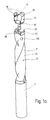
- the drilling tool shown in FIGS. 1 to 4 has a drill tip 10, one adjoining the drill tip, possibly as a cutting part trained chip removal part 12 and a rear on the chip removal part molded drill shaft 14 on.
- the drill tip 10 contains two main cutting edges 16 and two main open spaces adjoining the main cutting edges 20. Extend from the main cutting edges 16 in the drill tip 10 itself over the chip removal part 12 two spiral flutes 22, which up to Enough drill shaft.
- the separation point 30 is in the area of Chip removal part 12.
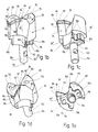
- the main cutting edges 16 each have two molded into the interchangeable tip 34, essentially paired roof-shaped against each other radially aligned cutting edges 16 ', 16 ", forming a double cutter arranged at the same radial distance from the drill axis 78 are. As can be seen in particular from FIGS. 1b and d, only overlaps one of the inner cutting edges 16 'the drill axis 78 while the other inner cutting edge 16 'adjoins this at a step 80.
- the roof tip 82 and the outwardly protruding cutting edge corners 84 of the two main cutting edges 16 are at the same radial distances arranged from the drill axis. Accordingly, the outside Cutting edges 16 "of the same length and the inner cutting edges 16 'different long trained.
- the cutting edges close at the top of the roof 16 ', 16 "in pairs a roof angle of 148 ° to 164 °. They ensure that the drill tip is centered in the borehole during the drilling process and not laterally is pushed away
- Chip flutes 22 are on the side of the cutting edges 16 ', 16 " the rake face 90 limited.
- FIGS. 1a to e are at a distance of the cutting edges 16 ', 16 "chip-shaped recesses 92 formed on their edges on the cutting edge side of the roof shape of the cutting edges 16 ', 16 "have an adapted edge profile.
- the one shown in FIG Variants are instead of the chip mold recesses, the Indentations 94 penetrating cutting edges 16 ', 16 "are provided.
- the interchangeable tip is on its side opposite the main open areas 20 provided with a coupling part 96, one with a complementary Centering and driver part 98 of the base body 32 meshing Has rotary driver 100.
- a coupling part 96 one with a complementary Centering and driver part 98 of the base body 32 meshing Has rotary driver 100.
- a complementary Centering and driver part 98 of the base body 32 meshing Has rotary driver 100 is additionally an axially central, in a receiving bore 102 of the base body 32 insertable and there positive and non-positive anchorable anchor pin 104 is provided.
- the rotary driver 100 contains four spacings from one another in the circumferential direction having partially cylindrical convex centering sections 106, which in a receptacle 108 on the base body side with the centering sections 106 complementary, part-cylindrical concave centering sections 110 fit intervention.
- the turning takes place on the flanks of between each two convex centering sections 106 arranged, axially open radial recesses 112, one each between two adjacent concaves Centering sections 110 of the base body 32 radially into the receptacle 108 protruding driver tooth 114 engages.
- the interchangeable tip has a projection which projects radially beyond the coupling part 96 flat shoulder surface 36, which over one on the anchoring pin 104 (FIGS. 1 and 2) or the coupling part 96 (FIGS. 3 and 4) acting Clamping mechanism against a flat end face 40 of the base body 32 can be pressed.
- the shoulder and end faces 36,40 are in two through the Chip grooves 22 in the circumferential direction of separate areas 36 ', 36 "and 40', 40" divided.
- the tensioning mechanism includes an example shown in Fig. 4a Tensioning screw 130.
- the clamping screw in a threaded hole 120, 120 'of the base body 32 arranged and engages with a conical tip in an eccentric Cone countersink 122, 122 'of the interchangeable tip.
- the cone depression 122 is located in the Receiving bore 102 located anchoring pin 104, while at 3a to c, the cone countersink 122 'in the area one of the radial recesses 112 of the coupling part is arranged, while the screw hole 120 'the receiving wall in the area of one of the Driver teeth 114 penetrates.
- the coupling part 96 the interchangeable tip 34 has a continuous transverse bore 132 through which one through a continuous counterbore 134 in a body side Driver part 98, 114 passed through and into a threaded bore 136 of the diametrically opposite driver part 98, 114 screwed in Countersunk screw 130 creating an axial direction in the area of the flat surfaces 36, 40 and in the circumferential direction in the area of the against each other adjacent flanks 138, 140 of the rotary driver 100 and the driver parts 98 backlash-free bracing between interchangeable tip 34 and base body 32 reaches through.
- the coupling part 96 has a flat surface 116, that of the bottom surface 118 faces the receptacle 108.
- the twist drill shown in FIGS. 5a and b has a drill tip 10, a to the drill tip adjoining cutting part 12 and a rear on Cutting part formed on drill shaft 14.
- the drill tip contains two Main cutting edges 16, one connecting the main cutting edges on the tip side Cutting edge 18 and two to the main cutting edges and to the Cross cutting edge adjacent main open spaces 20. From the main cutting edges 16 in the drill tip 10 extend over the cutting part 12 two spiral flutes 22 which are connected laterally by a secondary cutting edge 24 Guide chamfer 26 and limited by a secondary free area 28 are.
Abstract
Description
Die Erfindung betrifft ein Bohrwerkzeug mit einer Bohrerspitze, die zwei etwa gleiche Umfangsabstände voneinander aufweisende Hauptschneiden und zwei an die Hauptschneiden angrenzende Spanflächen und Hauptfreiflächen aufweist, mit einem an die Bohrerspitze axial anschließenden, gegebenenfalls als Schneidteil ausgebildeten Spanabfuhrteil, mit einem an dem der Bohrerspitze gegenüberliegenden Ende des Spanabfuhrteils angeordneten Bohrerschaft und mit zwei sich von den Hauptschneiden der Bohrerspitze aus wendelförmig über den Spanabfuhrteil erstreckenden Spannuten , wobei der Spanabfuhrteil aus einem mit dem Bohrerschaft einstückig verbundenen Grundkörper und einer mit der Bohrerspitze einstückig verbundenen Wechselspitze besteht, die an einer axialen Trennstelle form- und/oder kraftschlüssig miteinander verbindbar sind, und wobei die Wechselspitze in ihrer Gesamtheit aus einem härteren Werkstoff als der Grundkörper besteht, wobei die Wechselspitze mit einem nach der der Hauptfreifläche gegenüberliegenden Seite überstehenden Kupplungsteil einstückig verbunden ist, und das Kupplungsteil mindestens zwei über den Umfang verteilt angeordnete, teilzylindrisch konvexe Zentrierabschnitte aufweist, die in eine grundkörperseitige Aufnahme mit zu den konvexen Zentrierabschnitten komplementären, teilzylindrisch konkaven Zentrierabschnitten paßgenau eingreifen.The invention relates to a drilling tool with a drill tip, the two approximately main cutting edges having equal circumferential distances from one another and two rake faces and main open faces adjacent to the main cutting edges has, optionally with an axially connected to the drill tip designed as a cutting part chip removal part, with one on which Drill tip arranged opposite end of the chip removal part Drill shank and with two of the main cutting edges of the drill tip from helically extending over the chip removal part flutes, where the chip removal part from a piece connected to the drill shank Base body and an interchangeable tip connected in one piece to the drill tip exists, which is positive and / or non-positive at an axial separation point are interconnectable, and the interchangeable tip in their Entire consists of a harder material than the base body, whereby the interchangeable tip with one opposite to the main open area Side protruding coupling part is integrally connected, and the coupling part is arranged at least two distributed over the circumference, Has partially cylindrical convex centering sections, which in a body side Image with complementary to the convex centering sections engage partially cylindrical concave centering sections with a precise fit.
Der Spiralbohrer ist das meist verwendete Bohrwerkzeug zum Bohren ins Volle für Bohrungen bis etwa 18 mm Durchmesser. Als Werkstoff für Spiralbohrer werden legierter Werkzeugstahl, Schnellarbeitsstahl und Hartmetall verwendet. Erforderlichenfalls kann der Bohrer mit einer verschleißmindernden Schicht beispielsweise aus Titannitrit versehen werden. Der Bohrerverschleiß tritt vor allem in der Nähe der Bohrerspitze im Bereich der Hauptschneide und an der Führungsfase auf. Zur Beseitigung des Verschleißes ist es bekannt, den Bohrer an den jeweiligen Freiflächen nachzuschleifen. Als nachteilig wird dabei empfunden, daß der Bohrer beim Nachschleifen kürzer wird. Um diesen Nachteil zu vermeiden, ist es bei einem Bohrwerkzeug der eingangs angegebenen Art bekannt (DE-C-3709878), daß der Schneidteil aus einem mit dem Bohrerschaft einstückig verbundenen Grundkörper und einer mit der Bohrerspitze einstückig verbundenen Wechselspitze besteht, die an einer axialen Trennstelle form- und kraftschlüssig miteinander verbindbar sind.The twist drill is the most commonly used drilling tool for drilling into Full for holes up to approximately 18 mm in diameter. As a material for twist drills become alloyed tool steel, high-speed steel and carbide used. If necessary, the drill can be used with a wear-reducing Layer of titanium nitride, for example. The drill wear occurs mainly near the drill tip in the area of the main cutting edge and at the leading edge. To eliminate wear and tear it is known to regrind the drill on the respective open areas. As it is disadvantageous that the drill is shorter when regrinding becomes. In order to avoid this disadvantage, it is the case with a drilling tool known type known (DE-C-3709878) that the cutting part from a basic body connected in one piece with the drill shank and there is an interchangeable tip connected in one piece to the drill tip, which can be positively and non-positively connected at an axial separation point are.
Der Erfindung liegt die Aufgabe zugrunde, das bekannte Bohrwerkzeug der eingangs angegebenen Art dahingehend zu verbessern, daß mit herstellungstechnisch einfachen Mitteln eine hohe Festigkeit der Verbindung und eine exakte Zentrierung der Wechselspitze am Grundkörper erzielt werden kann.The invention has for its object the known drilling tool to improve the type specified in that with manufacturing technology simple means a high strength of the connection and exact centering of the interchangeable tip on the base body can be achieved can.
Zur Lösung dieser Aufgabe wird gemäß der Erfindung die im Anspruch 1
angegebene Merkmalskombination vorgeschlagen. Vorteilhafte Ausgestaltungen
und Weiterbildungen der Erfindung ergeben sich aus den abhängigen
Ansprüchen.To achieve this object, according to the invention, that in
Gemäß der Erfindung wird vorgeschlagen, daß das Kupplungsteil einen mit einem komplementären Mitnehmerteil des Grundkörpers kämmenden Drehmitnehmer aufweist. Vorteilhafterweise weist der Drehmitnehmer mindestens eine zwischen zwei benachbarten konvexen Zentrierabschnitten des Kupplungsteils angeordnete, axial offene Radialausnehmung für den Eingriff eines das Mitnehmerteil bildenden, zwischen zwei benachbarten konkaven Zentrierabschnitten des Grundkörpers radial in die Aufnahme überstehenden Mitnehmerzahn auf. Dadurch wird eine exakte Zentrierung der Wechselspitze am Grundkörper und damit eine Verbesserung der Bohrqualität erzielt. According to the invention it is proposed that the coupling part have a a complementary driver part of the base body meshing rotary driver having. The rotary driver advantageously has at least one between two adjacent convex centering sections of the coupling part arranged, axially open radial recess for the engagement of a the driver part forming between two adjacent concave centering sections of the base body protruding radially into the receptacle Drive tooth on. This ensures exact centering of the interchangeable tip achieved on the base body and thus an improvement in the drilling quality.
Vorteilhafterweise besteht die Wechselspitze in ihrer Gesamtheit zweckmäßig aus einem Schneidstoff aus der Gruppe Hartmetall oder Keramik und kann in diesem Falle als gesintertes Pulverspritzgußteil ausgebildet sein, Grundsätzlich kann die Wechselspitze auch aus einem verschleißfest beschichteten Werkzeugstahl hergestellt werden. Der Grundkörper besteht andererseits zweckmäßig aus Werkzeugstahl oder einem Schnellarbeitsstahl.The interchangeable tip advantageously exists in its entirety from a cutting material from the group of hard metal or ceramic and can be designed in this case as a sintered powder injection molded part, In principle, the interchangeable tip can also be coated with a wear-resistant coating Tool steel can be made. On the other hand, the basic body exists Appropriately made of tool steel or high-speed steel.
Eine bevorzugte Ausgestaltung der Erfindung sieht vor, daß die Hauptschneiden jeweils zwei in die Wechselspitze eingeformte, paarweise dachförmig gegeneinander angestellte, im wesentlichen radial ausgerichtete Schneidkanten aufweisen. Dabei können die Schneidkanten der beiden Hauptschneiden unter Bildung eines Doppelschneiders in gleichem Radialabstand von der Bohrerachse angeordnet werden, so daß sie beim Bohrvorgang über ihre gesamte Länge gleichzeitig im Eingriff stehen. Allerdings ist es hierbei zweckmäßig, wenn nur eine der beiden inneren Schneidkanten die Bohrerachse übergreift. An Ihren radial über den Außenumfang der Bohrerspitze überstehenden Schneidkantenecken gehen die Schneidkanten vorteilhafterweise in eine Führungskante über, an die in Umfangsrichtung eine sich über einen Teilumfang der Bohrerspitze erstreckende, radial über den Außenumfang der Bohrerspitze überstehende Führungsrippe angrenzt. Dabei sind die Dachspitze und die nach außen überstehenden Schneidkantenecken der beiden Hauptschneiden im Falle des Doppelschneiders in gleichen Radialabständen von der Bohrerachse angeordnet. Dementsprechend sind die äußeren Schneidkanten der beiden Hauptschneiden gleich lang ausgebildet, während die inneren Schneidkanten unterschiedlich lang sind. Eine bevorzugte Ausgestaltung der Erfindung sieht vor, daß die Schneidkanten mit einer senkrecht zur Bohrerachse ausgerichteten Ebene einen Winkel von 2° bis 30°, vorzugsweise 8° bis 16° einschließen, so daß die Schneidkanten der Hauptschneiden paarweise einen Dachwinkel von 120° bis 176°, vorzugsweise von 148° bis 164° einschließen.A preferred embodiment of the invention provides that the main cutting edges Two roof-shaped in pairs, each molded into the interchangeable tip against each other, essentially radially aligned Have cutting edges. The cutting edges of the two Main cutting to form a double cutter at the same radial distance be arranged by the drill axis so that they during the drilling process are engaged simultaneously over their entire length. However it is useful if only one of the two inner cutting edges overlaps the drill axis. On your radially over the outer circumference of the drill tip protruding cutting edge corners go the cutting edges advantageously in a leading edge, to which in the circumferential direction a radially extending over a partial circumference of the drill tip the guide rib projects beyond the outer circumference of the drill tip. The top of the roof and the cutting edge corners protruding outwards of the two main cutting edges in the case of the double cutter in the same Radial distances from the drill axis. Accordingly the outer cutting edges of the two main cutting edges are of equal length formed while the inner cutting edges are of different lengths. A preferred embodiment of the invention provides that the cutting edges with a plane aligned perpendicular to the drill axis Include angles of 2 ° to 30 °, preferably 8 ° to 16 °, so that the Cutting edges of the main cutting edges in pairs have a roof angle of 120 ° include up to 176 °, preferably from 148 ° to 164 °.
Die in die Wechselspitze eingeformten Schneidkanten können zumindest partiell angefast und/oder verrundet und gegebenenfalls wellenförmig ausgebildet sein. Weiter können in die Spanflächen vorzugsweise bis zu den Schneidkanten reichende Eindellungen, Erhöhungen, Stufen, Rippen eingeformt werden. Für die Spanbildung besonders günstig ist es, wenn in die Spanflächen Spanformmulden eingeformt sind, die vorzugsweise im axialen Abstand von den Schneidkanten angeordnet sind. Die Spanformmulden können dabei zumindest an ihren schneidkantenseitigen Rändern einen der Dachform der Schneidkanten angepaßten Randverlauf aufweisen. Die im wesentlichen achsparallelen, radial ausgerichteten Spanflächen begrenzen eine in Spanablaufrichtung in die Spanfördemuten mündenden Spanraum.The cutting edges molded into the interchangeable tip can at least partially chamfered and / or rounded and possibly wavy his. Further can preferably into the rake faces Indentations, ridges, steps, ribs reaching the cutting edges become. For chip formation, it is particularly favorable if in the Rake faces are molded in, which are preferably axial Distance from the cutting edges are arranged. The chip mold troughs can at least at their cutting edge edges one of the Have roof shape of the cutting edges adapted edge course. The in limit essential axially parallel, radially aligned rake faces a chip space opening in the chip discharge direction into the chip conveying grooves.
Für die kraftschlüssige Verbindung zwischen Wechselspitze und Grundkörper ist es von Vorteil, wenn die Wechselspitze eine im wesentlichen radial über das Kupplungsteil überstehende plane Schulterfläche aufweist, die vorzugsweise mittels eines Spannmechanismus gegen eine plane Stirnfläche des Grundkörpers anpreßbar ist. Die Schulter- und Stirnflächen sind dabei zweckmäßig in je zwei durch die Spannuten in Umfangsrichtung voneinander getrennte Flächenpartien unterteilt. Eine weitere Verbesserung in dieser Hinsicht kann dadurch erzielt werden, daß das Kupplungsteil eine im wesentlichen radial über den Verankerungszapfen überstehende freie Schulterfläche aufweist, die vorzugsweise mittels eines Spannmechanismus gegen eine die Aufnahme begrenzende Bodenfläche anpreßbar ist.For the non-positive connection between interchangeable tip and body it is advantageous if the interchangeable tip is essentially radial has over the coupling part projecting flat shoulder surface, which preferably by means of a clamping mechanism against a flat end face the base body can be pressed. The shoulder and end faces are included expediently in two by the flutes in the circumferential direction from each other divided separate areas. Another improvement in this In this regard, the coupling part can be achieved essentially free shoulder area protruding radially over the anchoring pin has, which preferably by means of a clamping mechanism a bottom surface limiting the receptacle can be pressed.
Zur Herstellung einer form- und kraftschlüssigen Verbindung zwischen der Wechselspitze und dem Grundkörper ist vorteilhafterweise in dem Kupplungsteil mindestens eine im wesentlichen radial ausgerichtete, konische Senkung angeordnet, in die ein in einer grundkörperfesten radialen Gewindebohrung angeordneter Gewindestift mit einer Kegelspitze form- und kraftschlüssig eingreift. Die Senkung ist dabei zweckmäßig in einen Drehmitnehmer des Kupplungsteils eingeformt, während die Gewindebohrung einen der Mitnehmerteile des Grundkörpers durchdringt.To create a positive and non-positive connection between the Interchangeable tip and the base body is advantageously in the coupling part at least one essentially radially oriented, conical Counterbore arranged in a radial threaded hole fixed in the body arranged setscrew with a conical tip positive and non-positive intervenes. The reduction is expedient in a rotary driver of the coupling part molded, while the threaded bore one of the Carrier parts of the base body penetrates.
Eine weitere Verbindungsvariante zwischen Wechselspitze und Grundkörper sieht vor, daß das Kupplungsteil der Wechselspitze eine durchgehende Querbohrung aufweist, durch die eine durch eine Durchgangsbohrung des einen Mitnehmerteils hindurchgeführte und in eine Gewindebohrung des gegenüberliegenden Mitnehmerteils eingedrehte Spannschraube unter Erzeugung einer in axialer Richtung und in Umfangsrichtung spielfreien Verspannung zwischen Wechselspitze und Grundkörper hindurchgreift.Another connection variant between interchangeable tip and body provides that the coupling part of the interchangeable tip is continuous Has transverse bore through which a through hole of the a driver part passed and into a threaded hole in the opposite Driver part screwed in tensioning screw under generation a backlash-free bracing in the axial direction and in the circumferential direction reaches between interchangeable tip and base body.
Vor allem bei Bohrwerkzeugen mit sehr kleinem Durchmesser, bei denen eine mechanische Verbindung zwischen Wechselspitze und Grundkörper problematisch ist, sind die Wechselspitze und der Grundkörper an ihren zwischen Kupplungsteil und Aufnahme angeordneten Fügestellen zweckmäßig miteinander laserverschweißt oder hartverlötet. Especially for drilling tools with a very small diameter, where a mechanical connection between the tip and the body problem is the interchangeable tip and the base body on their Appropriate joints between the coupling part and the receptacle laser welded or brazed together.
Zur Verbesserung des Bohrergebnisses kann mindestens eine den Grundkörper und die Wechselspitze axial oder spiralig durchdringende, die Trennstelle überbrückende Kühlmittelbohrung vorgesehen werden.To improve the drilling result, at least one can use the base body and the interchangeable tip axially or spirally penetrating, the separation point bridging coolant hole are provided.
Um die Lagerhaltung zu reduzieren, können auf einen Grundkörper mit gegebenem Außendurchmesser auch Wechselspitzen mit hiervon abweichendem Außendurchmesser aufgesteckt werden.To reduce inventory, you can use a basic body with a given Outside diameter also interchangeable tips with different Outside diameter can be attached.
Im folgenden wird die Erfindung anhand einiger in der Zeichnung in schematischer Weise dargestellter Ausführungsbeispiele näher erläutert. Es zeigen
- Fig. 1a
- eine Seitenansicht eines Bohrwerkzeugs mit Wechselspitze in schaubildlicher Explosionsdarstellung;
- Fig. 1b bis e
- die Wechselspitze nach Fig. 1a in verschiedenen perspektivischen Ansichten;
- Fig. 1f
- eine ausschnittsweise vergrößerte Darstellung des Grundkörpers des Bohrwerkzeugs nach Fig. 1a;
- Fig. 2
- ein gegenüber Fig. 1 abgewandeltes Ausführungsbeispiel einer Wechselspitze in einer perspektivischen Darstellung entsprechend Fig. 1d;
- Fig. 3a und b
- ein weiteres gegenüber Fig. 1 abgewandeltes Ausführungsbeispiel einer Wechselspitze in zwei perspektivischen Darstellungen;
- Fig. 3c
- eine ausschnittsweise Darstellung des Grundkörpers für die Wechselspitze nach Fig. 3a und b;
- Fig. 4a
- eine schaubildliche Explosionsdarstellung eines weiteren abgewandelten Ausführungsbeispiels eines Bohrwerkzeugs mit Wechselspitze;
- Fig. 4b
- eine Stirnseitenansicht des Grundkörpers des Bohrwerkzeugs nach Fig. 4a,
- Fig. 5a
- eine Seitenansicht eines Spiralbohrers mit Wechselspitze;
- Fig. 5b
- eine Draufsicht auf die Bohrerspitze in gegenüber Fig. 1a vergrößerter Darstellung;
- Fig. 1a
- a side view of a drilling tool with interchangeable tip in a diagrammatic exploded view;
- 1b to e
- the change tip of Figure 1a in different perspective views.
- Fig. 1f
- a fragmentary enlarged view of the base body of the drilling tool according to Fig. 1a;
- Fig. 2
- an embodiment of an interchangeable tip modified from FIG. 1 in a perspective view corresponding to FIG. 1d;
- 3a and b
- another embodiment of an interchangeable tip modified from FIG. 1 in two perspective representations;
- Fig. 3c
- a partial representation of the base body for the interchangeable tip according to Fig. 3a and b;
- Fig. 4a
- a diagrammatic exploded view of a further modified embodiment of a drilling tool with an interchangeable tip;
- Fig. 4b
- 4a shows an end view of the main body of the drilling tool according to FIG. 4a,
- Fig. 5a
- a side view of a twist drill with interchangeable tip;
- Fig. 5b
- a plan view of the drill tip in an enlarged view compared to FIG. 1a;
Die in der Zeichnung dargestellten Bohrwerkzeuge sind an einer Trennstelle
30 zweigeteilt und bestehen aus einem einen Bohrerschaft 14 tragenden
Grundkörper 32 und einer eine Bohrerspitze 10 tragenden Wechselspitze 34,
die an der Trennstelle 30 form- und kraftschlüssig miteinander verbindbar
sind. Während der Grundkörper 32 aus Werkzeugstahl oder einem
Schnellarbeitsstahl besteht, ist die Wechselspitze in ihrer Gesamtheit als
Formteil aus einem Schneidstoff aus der Gruppe Hartmetall oder Keramik
gebildet, das als gesintertes Pulverspritzgußteil hergestellt ist. Grundsätzlich
ist es auch möglich, die Wechselspitze aus einem verschleißfest beschichteten
Werkzeugstahl herzustellen.The drilling tools shown in the drawing are at a
Das in den Fig. 1 bis 4 gezeigte Bohrwerkzeug weist eine Bohrerspitze 10,
einen an die Bohrerspitze anschließenden, gegebenenfalls als Schneidteil
ausgebildeten Spanabfuhrteil 12 und einen rückwärtig am Spanabfuhrteil
angeformten Bohrerschaft 14 auf. Die Bohrerspitze 10 enthält zwei Hauptschneiden
16 und zwei an die Hauptschneiden anschließende Hauptfreiflächen
20. Von den Hauptschneiden 16 in der Bohrerspitze 10 aus erstrecken
sich über den Spanabfuhrteil 12 zwei spiralige Spannuten 22, die bis zum
Bohrerschaft reichen. Die Trennstelle 30 befindet sich im Bereich des
Spanabfuhrteils 12.The drilling tool shown in FIGS. 1 to 4 has a
Die Hauptschneiden 16 weisen jeweils zwei in die Wechselspitze 34 eingeformte,
paarweise dachförmig gegeneinander angestellte, im wesentlichen
radial ausgerichtete Schneidkanten 16',16" auf, die unter Bildung eines Doppelschneiders
in gleichem Radialabstand von der Bohrerachse 78 angeordnet
sind. Wie insbesondere aus Fig. 1b und d zu ersehen ist, übergreift nur
eine der inneren Schneidkanten 16' die Bohrerachse 78, während die andere
innere Schneidkante 16' sich außermittig an einer Stufe 80 an diese anschließt.
Die Dachspitze 82 und die nach außen überstehenden Schneidkantenecken
84 der beiden Hauptschneiden 16 sind in gleichen Radialabständen
von der Bohrerachse angeordnet. Dementsprechend sind die äußeren
Schneidkanten 16" gleich lang und die inneren Schneidkanten 16' unterschiedlich
lang ausgebildet. An der Dachspitze schließen die Schneidkanten
16',16" paarweise einen Dachwinkel von 148° bis 164° ein. Sie sorgen dafür,
daß die Bohrerspitze beim Bohrvorgang im Bohrloch zentriert und nicht seitlich
abgedrängt wird.The main cutting edges 16 each have two molded into the
Die radial über den Außenumfang der Bohrerspitze überstehenden Schneidkantenecken
84 gehen in eine Führungskante 86 über, an die in Umfangsrichtung
eine sich über einen Teilumfang der Bohrerspitze 10 erstreckende,
radial über den Außenumfang überstehende Führungsrippe 88 angrenzt.The cutting edge corners protruding radially over the outer circumference of the
Die in Spanablaufrichtung unmittelbar hinter den Hauptschneiden 16 beginnenden
Spannuten 22 sind auf der Seite der Schneidkanten 16',16" durch
die Spanfläche 90 begrenzt. Im Falle der Fig. 1a bis e sind im Abstand von
den Schneidkanten 16',16" Spanformmulden 92 eingeformt, die an ihren
schneidkantenseitigen Rändern eine der Dachform der Schneidkanten
16',16" angepaßten Randverlauf aufweisen. Bei der in Fig. 2 gezeigten
Ausführungsvariante sind anstelle der Spanformmulden mehrere, die
Schneidkanten 16',16" durchdringende Eindellungen 94 vorgesehen.Those beginning in the chip flow direction immediately behind the main cutting edges 16
Chip flutes 22 are on the side of the cutting edges 16 ', 16 "
the
An ihrer den Hauptfreiflächen 20 gegenüberliegenden Seite ist die Wechselspitze
mit einem Kupplungsteil 96 versehen, das einen mit einem komplementären
Zentrier- und Mitnehmerteil 98 des Grundkörpers 32 kämmenden
Drehmitnehmer 100 aufweist. Bei den Ausführungsbeispielen nach Fig. 1
und 2 ist zusätzlich ein achszentral überstehender, in eine Aufnahmebohrung
102 des Grundkörpers 32 einführbarer und dort form- und kraftschlüssig
verankerbarer Verankerungszapfen 104 vorgesehen.The interchangeable tip is on its side opposite the main
Der Drehmitnehmer 100 enthält vier in Umfangsrichtung einen Abstand voneinander
aufweisende teilzylindrisch konvexe Zentrierabschnitte 106, die in
eine grundkörperseitige Aufnahme 108 mit zu den Zentrierabschnitten 106
komplementären, teilzylindrischen konkaven Zentrierabschnitten 110 paßgenau
eingreifen. Die Drehmitnahme erfolgt über die Flanken der zwischen je
zwei konvexen Zentrierabschnitten 106 angeordneten, axial offenen Radialausnehmungen
112, in die je ein zwischen zwei benachbarten konkaven
Zentrierabschnitten 110 des Grundkörpers 32 radial in die Aufnahme 108
überstehender Mitnehmerzahn 114 eingreift.The
Die Wechselspitze weist eine radial über das Kupplungsteil 96 überstehende
plane Schulterfläche 36 auf, die über einen auf den Verankerungszapfen
104 (Fig. 1 und 2) oder das Kupplungsteil 96 (Fig. 3 und 4) einwirkenden
Spannmechanismus gegen eine plane Stirnfläche 40 des Grundkörpers 32
anpreßbar ist. Die Schulter- und Stirnflächen 36,40 sind in je zwei durch die
Spannuten 22 in Umfangsrichtung voneinander getrennte Flächenpartien
36',36" sowie 40',40" unterteilt.The interchangeable tip has a projection which projects radially beyond the
Der Spannmechanismus umfaßt eine beispielhaft in Fig. 4a dargestellte
Spannschraube 130. Bei den in Fig. 1 bis 3 gezeigten Ausführungsbeispielen
ist die Spannschraube in einer Gewindebohrung 120, 120' des Grundkörpers
32 angeordnet und greift mit einer Kegelspitze in eine exzentrische
Konussenkung 122, 122' der Wechselspitze ein. Bei dem Ausführungsbeispiel
nach Fig. 1 und 2 befindet sich die Konussenkung 122 in dem in der
Aufnahmebohrung 102 befindlichen Verankerungszapfen 104, während bei
dem Ausführungsbeispiel nach Fig. 3a bis c die Konussenkung 122' im Bereich
einer der Radialausnehmungen 112 des Kupplungsteils angeordnet ist,
während die Schraubbohrung 120' die Aufnahmewand im Bereich eines der
Mitnehmerzähne 114 durchdringt.The tensioning mechanism includes an example shown in Fig.
Bei dem Ausführungsbeispiel nach Fig. 4a und b weist das Kupplungsteil 96
der Wechselspitze 34 eine durchgehende Querbohrung 132 auf, durch die
eine durch eine durchgehende Senkbohrung 134 in einen grundkörperseitigen
Mitnehmerteil 98,114 hindurchgeführte und in eine Gewindebohrung 136
des diametral gegenüberliegenden Mitnehmerteils 98,114 eingedrehte
Senkkopfschraube 130 unter Erzeugung einer in axialer Richtung im Bereich
der Planflächen 36, 40 und in Umfangsrichtung im Bereich der gegeneinander
anliegenden Flanken 138,140 der Drehmitnehmer 100 und der Mitnehmerteile
98 spielfreien Verspannung zwischen Wechselspitze 34 und Grundkörper
32 hindurchgreift.In the exemplary embodiment according to FIGS. 4 a and b, the
Weiter weist das Kupplungsteil 96 eine Planfläche 116 auf, die der Bodenfläche
118 der Aufnahme 108 zugewandt ist.Furthermore, the
Der in Fig. 5a und b gezeigte Spiralbohrer weist eine Bohrerspitze 10, einen
an die Bohrerspitze anschließenden Schneidteil 12 und einen rückwärtig am
Schneidteil angeformten Bohrerschaft 14 auf. Die Bohrerspitze enthält zwei
Hauptschneiden 16, eine die Hauptschneiden spitzenseitig miteinander verbindende
Querschneide 18 und zwei an die Hauptschneiden und an die
Querschneide anschließende Hauptfreiflächen 20. Von den Hauptschneiden
16 in der Bohrerspitze 10 aus erstrecken sich über den Schneidteil 12 zwei
spiralige Spannuten 22, die seitlich durch eine Nebenschneide 24 mit anschließender
Führungsfase 26 sowie durch eine Nebenfreifläche 28 begrenzt
sind.The twist drill shown in FIGS. 5a and b has a
Claims (32)
- A drilling tool, comprising a drill tip (10) which has two main cutting edges (16) positioned at approximately equal circumferential distances from each other, and two cutting faces (90) and front rakes (20) adjoining the main cutting edges, a chip removal part (12) which axially adjoins the drill tip and which may be formed to be a cutting part, a drill shank (14) which is positioned at the end of the chip removal part (12) opposing the drill tip (10), and two chip flutes (22) which extend in a helical manner over the chip removal part (12) starting at the main cutting edges (16) of the drill tip (10), wherein the chip removal part (12) consists of a base body (32) which is connected to the drill shank (14) as one part and an exchangeable tip (34) which is connected to the drill tip (10) as one part, which are connectable to each other in a form- and/or frictional-fitting manner at an axial separation point (30), wherein the exchangeable tip (34) as a whole consists of a material which is harder than the base body (32), wherein the exchangeable tip (34) is connected in one piece to a coupling piece (96) which protrudes over the side opposing the front rake (20), and wherein the coupling piece (96) has at least two partially cylindrical, convex centering sections (106) which are positioned distributed over the circumference and which fit exactly into a bushing (108) at the base body, which has partially cylindrical, concave centering sections (110) which are complementary to the convex centering sections (106), characterized in that the coupling piece (96) has a driver (100) which meshes with a complementary driving part (98) of the base body (32).
- The drilling tool of claim 1, characterized in that the driver (100) has at least one axially open radial recess (112), which is positioned between two adjacent convex centering sections (106) of the coupling piece (96), for the engagement of a driver tooth (114) which radially protrudes into the bushing (108) between two adjacent concave centering sections (110) of the base body (32).
- The drilling tool of one of claims 1 or 2, characterized in that the coupling piece (96) has an anchoring pin (104) which protrudes centrally over the exchangeable tip (34) and which can be inserted into the base body (32) and anchored there in a form- and/or frictional-fitting manner.
- The drilling tool of one of claims 1 to 3, characterized in that the exchangeable tip (34) has a plane shoulder (36) which protrudes generally radially over the coupling piece (96), the shoulder (36) preferably being pressable against a plane face (40) of the base body (32) by means of a clamping mechanism.
- The drilling tool of claim 4, characterized in that the shoulder (36) and face (40) are each subdivided into two areas (36', 36"; 40', 40") which are separated from each other in the circumferential direction by the flutes (22).
- The drilling tool of one of claims 1 to 5, characterized in that at least one generally radially aligned conical countersink (122') is positioned in the coupling piece (96), a threaded bolt having a conical tip, which is positioned in a generally radial threaded bore (120') in the base body, being engaged in a form- and friction-fitting manner in the countersink.
- The drilling tool of claim 6, characterized in that the conical countersink (122') is formed into one of the drivers (100) of the coupling piece (96), and that the threaded bore (120') penetrates one of the driving pieces (114) of the base body (32).
- The drilling tool of one of claims 1 to 7, characterized in that the coupling piece (96) of the exchangeable tip (34) has a continuous cross bore (132), through which a clamping screw (130) extends, which is led through a bore (134) of the driving part (98, 114) of the base body and which is screwed into a threaded bore (136) of the opposing driving part (98, 114), by which a tensioning between the exchangeable tip (34) and the base body (32) without any free play in the axial and circumferential directions is created.
- The drilling tool of one of claims 1 to 8, characterized in that the coupling piece (96) has an end face (116) which protrudes generally radially over the anchoring pin (104), the end face (116) being pressable against a bottom face (118) which delimits the bushing (108).
- The drilling tool of one of claims 1 to 9, characterized in that the exchangeable tip (34) and the base body (32) are laser-welded or hard-soldered to each other at their joining locations which are positioned between the coupling piece (96) and the bushing (108).
- The drilling tool of one of claims 1 to 10, characterized by a coolant bore (66) which penetrates the base body (32) and the exchangeable tip (34) and which bridges the separating point (30).
- The drilling tool of one of claims 1 to 11, characterized in that the base body (32) and the exchangeable tip (34) have outer diameters which differ from one another.
- The drilling tool of claim 1 to 12, characterized in that the exchangeable tip (34) consists of a cutting material from the group of hard metals, ceramics or tribologically resistant coated tool steels.
- The drilling tool of claim 1 or 13, characterized in that the exchangeable tip (34) is formed to be a sintered powder injection molding part.
- The drilling of claim 1 to 14, characterized in that the base body (32) consists of tool steel or a high-speed steel.
- The drilling tool of one of claims 1 to 15, characterized in that the main cutting edges (16) each have two cutting edges (16', 16") which are formed into the exchangeable tip (34), sloped against each other in a roof shape, and aligned in a generally radial direction.
- The drilling tool of claim 16, characterized in that the cutting edges (16', 16") of the two main cutting edges (16) are positioned in equal radial distances from the drill axis (78), forming a double cutter.
- The drilling tool of one of claims 16 or 17, characterized in that only one of the two inner cutting edges (16') overlaps with the drill axis (78).
- The drilling tool of one of claims 16 to 18, characterized in that the cutting edge corners (4) which protrude radially over the outer circumference of the drill tip (10) merge into generally axially aligned guide edges (86).
- The drilling tool of claim 19, characterized in that a guide rib (88) which radially protrudes over the outer circumference and extends over part of the circumference of the drill tip (10) adjoins the guide edge (86) in the circumferential direction.
- The drilling tool of one of claims 16 to 20, characterized in that the peak (82) and the outwardly protruding cutting edge corners (84) are positioned in equal radial distances from the drill axis (78).
- The drilling tool of one of claims 16 to 21, characterized in that the outer cutting edges (16") of the two main cutting edges (16) are of equal length and the inner cutting edges (16') are of different length.
- The drilling tool of one of claims 16 to 22, characterized in that the cutting edges and a plane which is perpendicular to the drill axis (78) include an angle of 2° to 30°, preferably of 8° to 16°.
- The drilling tool of one of claims 16 to 23, characterized in that the pairs of cutting edges (16', 16") of the main cutting edges (16) include a roof angle of 120° to 176°, preferably of 148° to 164°.
- The drilling tool of one of claims 16 to 24, characterized in that the cutting edges (16', 16") are formed to be wave-shaped.
- The drilling tool of one of claims 16 to 25, characterized in that indentations (94), raised portions, steps, or ribs, which preferably reach the cutting edges (16', 16"), are formed into the cutting faces (90).
- The drilling tool of one of claims 16 to 26, characterized in that the cutting edges are at least partially beveled and/or rounded-off.
- The drilling tool of one of claims 1 to 27, characterized in that the exchangeable tip (34) is formed to be a helical drill tip having a chisel edge (18).
- The drilling tool of one of claims 16 to 28, characterized in that chip forming hollows (92) are formed into the cutting faces (90), which are preferably positioned at an axial distance with respect to the cutting edges (16', 16").
- The drilling tool of claim 29, characterized in that the chip forming hollows (92) have sides corresponding in shape to the roof-shape of the cutting edges (16', 16") at least at their sides adjoining the cutting edges.
- The drilling tool of one of claims 1 to 30, characterized in that the cutting faces (90) which are generally axially parallel and radially aligned delimit a chip space which merges into the chip flutes (22) in the direction of chip travel.
- The drilling tool of one of claims 1 to 31, characterized in that the exchangeable tip (34) has at least one coolant bore (124) which is generally parallel to the drill axis and exits in the region of the front rakes (20).
Applications Claiming Priority (3)
| Application Number | Priority Date | Filing Date | Title |
|---|---|---|---|
| DE19507469 | 1995-03-03 | ||
| DE19507469 | 1995-03-03 | ||
| PCT/EP1996/000570 WO1996027469A1 (en) | 1995-03-03 | 1996-02-10 | Drilling tool |
Publications (2)
| Publication Number | Publication Date |
|---|---|
| EP0813459A1 EP0813459A1 (en) | 1997-12-29 |
| EP0813459B1 true EP0813459B1 (en) | 2003-07-02 |
Family
ID=7755559
Family Applications (1)
| Application Number | Title | Priority Date | Filing Date |
|---|---|---|---|
| EP96904056A Expired - Lifetime EP0813459B1 (en) | 1995-03-03 | 1996-02-10 | Drilling tool |
Country Status (8)
| Country | Link |
|---|---|
| US (1) | US6012881A (en) |
| EP (1) | EP0813459B1 (en) |
| JP (1) | JPH11500967A (en) |
| AT (1) | ATE244092T1 (en) |
| AU (1) | AU4830696A (en) |
| DE (2) | DE19605157A1 (en) |
| IL (1) | IL117297A (en) |
| WO (1) | WO1996027469A1 (en) |
Cited By (4)
| Publication number | Priority date | Publication date | Assignee | Title |
|---|---|---|---|---|
| DE102007044095A1 (en) | 2007-09-14 | 2009-03-19 | Hartmetall-Werkzeugfabrik Paul Horn Gmbh | Drilling tool with drill bit |
| DE102013205889B3 (en) * | 2013-04-03 | 2014-05-28 | Kennametal Inc. | Coupling structure e.g. cutting head for rotary tool e.g. drilling tool, has coupling pin with clamping faces and stop surfaces that are arranged in different dispensing areas |
| DE102013209371A1 (en) | 2013-05-21 | 2014-11-27 | Kennametal Inc. | Coupling part, in particular cutting head for a rotary tool and this complementary coupling part and rotary tool |
| US11565356B2 (en) | 2017-07-13 | 2023-01-31 | Kennametal Inc. | Method for producing a cutting head |
Families Citing this family (107)
| Publication number | Priority date | Publication date | Assignee | Title |
|---|---|---|---|---|
| WO1997006913A1 (en) * | 1995-08-21 | 1997-02-27 | Komet Präzisionswerkzeuge Robert Breuning Gmbh | Drilling tool |
| SE511429C2 (en) | 1996-09-13 | 1999-09-27 | Seco Tools Ab | Tools, cutting part, tool body for cutting machining and method of mounting cutting part to tool body |
| SE510533C2 (en) * | 1996-11-04 | 1999-05-31 | Seco Tools Ab | Tools for cutting machining |
| WO1998042469A1 (en) * | 1997-03-25 | 1998-10-01 | Gühring, Jörg | Boring bit |
| IL120948A0 (en) * | 1997-05-29 | 1997-09-30 | Iscar Ltd | Cutting tool assembly |
| DE19856986A1 (en) | 1997-12-22 | 1999-07-08 | Komet Stahlhalter Werkzeug | Production of drilling tool |
| US5976143A (en) * | 1997-12-23 | 1999-11-02 | Johnson & Johnson Professional, Inc. | Orthopedic reaming instrument |
| DE59911756D1 (en) * | 1998-09-29 | 2005-04-21 | Zimmer Gmbh Winterthur | Hollow cutter for tissue |
| SE512053C2 (en) * | 1998-12-22 | 2000-01-17 | Seco Tools Ab | Tools and cutting heads for cutting machining |
| DE19914170C1 (en) | 1999-03-29 | 2000-03-16 | Kennametal Inc | Drill with basic body incorporates exchangeable cutting insert located in accommodation open to drill point and penetrating basic body crossways to its longitudinal axis |
| PT1200222E (en) * | 1999-08-03 | 2003-08-29 | Kennametal Inc | SUBSTITUABLE THREAD DRILL |
| DE19963636C2 (en) * | 1999-12-29 | 2002-02-28 | Heraeus Quarzglas | Drilling device for brittle materials |
| SE519895C2 (en) * | 2000-07-06 | 2003-04-22 | Sandvik Ab | Tip and rotatable tool with interchangeable tip at the tool's cutting end free end |
| DE10042990A1 (en) * | 2000-09-01 | 2002-03-28 | Kennametal Inc | Run-out cutting tool, e.g. B. drills |
| US6485235B1 (en) | 2001-05-08 | 2002-11-26 | Allied Machine & Engineering Corp. | Cutting tool assembly with replaceable cutting head |
| SE523205C2 (en) * | 2001-06-06 | 2004-04-06 | Sandvik Ab | Rotatable tool with interchangeable cutting tip at the tool's cutting end free end |
| US20030039523A1 (en) * | 2001-07-13 | 2003-02-27 | Kemmer Hartmetallwerkzeuge Gmbh | Drilling or boring tool |
| US6506003B1 (en) * | 2001-10-02 | 2003-01-14 | Kennametal Inc. | Cutting tool |
| SE0103752L (en) * | 2001-11-13 | 2003-05-14 | Sandvik Ab | Rotatable tool for chip separating machining and cutting part herewith |
| DE10161823A1 (en) * | 2001-12-15 | 2003-06-26 | Tigra Hartstoff Gmbh | Cylinder head drill or similar tool with hard metal cutting |
| DE10207257B4 (en) * | 2002-02-21 | 2021-02-18 | Kennametal Inc. | Rotary cutting tool with exchangeable cutting insert |
| US6582164B1 (en) * | 2002-02-25 | 2003-06-24 | Kennametal Inc. | Roller twist drill |
| US6938961B2 (en) * | 2002-03-21 | 2005-09-06 | Cutting Edge Technologies, Llc | Apparatus for breaking up solid objects |
| JP3818196B2 (en) * | 2002-03-29 | 2006-09-06 | 三菱マテリアル株式会社 | Throw-away drill |
| DE10220023A1 (en) * | 2002-05-04 | 2003-11-20 | Tts Tooltechnic Systems Ag | drill |
| US20050098355A1 (en) * | 2003-03-03 | 2005-05-12 | Broom Gilbert R. | Method and apparatus for boring through a solid material |
| US20040195008A1 (en) * | 2003-03-03 | 2004-10-07 | Broom Gilbert R. | Method and apparatus for tapping a blast furnace |
| DE10314889A1 (en) * | 2003-04-01 | 2004-10-14 | Komet Group Holding Gmbh | Tool for machine tools |
| DE10316116A1 (en) * | 2003-04-04 | 2004-10-14 | Tbt Tiefbohrtechnik Gmbh + Co | Single-lip drill and method for its production |
| US7150589B2 (en) * | 2003-10-01 | 2006-12-19 | Greenlee Textron Inc. | Deburring tool |
| SE525996C2 (en) * | 2003-10-16 | 2005-06-07 | Sandvik Ab | Process for producing cutting tools in which two parts are joined by laser welding |
| US7083367B2 (en) * | 2003-10-20 | 2006-08-01 | Gene Delett | Adaptor device for holding a blade |
| US7018145B2 (en) * | 2003-11-07 | 2006-03-28 | Allied Machine & Engineering Corp. | Spade drill insert having curved cutting edges |
| US7547166B2 (en) * | 2003-11-07 | 2009-06-16 | Allied Machine & Engineering Corp. | Spade drill insert having helical margins |
| US7011478B2 (en) * | 2003-11-07 | 2006-03-14 | Allied Machine & Engineering Corp. | Spade drill insert having helical margins |
| EP1533061A1 (en) * | 2003-11-11 | 2005-05-25 | Yestool Co., Ltd. | Structure for securing insert to insert drill |
| DE10353514A1 (en) | 2003-11-14 | 2005-06-23 | Heule, Ulf | Drilling plate with clamping attachment in a base body |
| US7131799B2 (en) | 2003-12-19 | 2006-11-07 | Allied Machine & Engineering Corp. | Cutting insert with helical geometry and holder therefor |
| DE102004023710B4 (en) * | 2004-05-11 | 2014-07-10 | Komet Group Gmbh | Machine tool with interchangeable cutting plate and interchangeable cutting plate for a machine tool |
| US7244081B2 (en) * | 2004-09-09 | 2007-07-17 | Ingersoll Cutting Tool Company | Drill adapter for drill having central and lateral cutting inserts |
| SE528245C2 (en) * | 2004-09-23 | 2006-10-03 | Seco Tools Ab | Tool head with mounting section with axial and radial stop surfaces |
| US7309196B2 (en) * | 2004-10-05 | 2007-12-18 | Kennametal Inc. | Modular drill |
| IL164888A (en) * | 2004-10-28 | 2009-07-20 | Iscar Ltd | Cutting tool assembly and cutting head therefor |
| DE102005047510A1 (en) | 2005-10-04 | 2007-04-05 | Gühring Ohg | Chip removing tool e.g. reamer, has tool head mounted at tool shanks as separate part, and made in single-piece from hard material with function layer that contains super hard material such as cubic boron nitride or polycrystalline diamond |
| DE102006012382A1 (en) | 2006-03-17 | 2007-09-20 | Kennametal Inc. | Turning tool, in particular drilling tool and tool head for a turning tool |
| DE102006049088A1 (en) | 2006-10-13 | 2008-04-24 | Kennametal Inc. | Modular drilling tool and method for its manufacture |
| SE0602263L (en) * | 2006-10-26 | 2008-03-25 | Seco Tools Ab | Cutting element made of cemented carbide with friction surface for mounting wrench |
| DE102006035452A1 (en) * | 2006-11-17 | 2008-05-21 | Hilti Ag | Drilling tool with hard material insert |
| DE102007005463B3 (en) * | 2007-01-30 | 2008-05-29 | Ting Fong Electric & Machinery Co. Ltd., Sanchung | Process to manufacture a drill/milling tool with forged cylinder and sintered cutter ring joined by keyways |
| SE531188C2 (en) * | 2007-05-29 | 2009-01-13 | Sandvik Intellectual Property | Drill body for chip separating machining |
| IL186967A0 (en) * | 2007-10-28 | 2008-02-09 | Iscar Ltd | Cutting head of a reamer |
| CN102049535B (en) * | 2008-04-03 | 2013-07-31 | 钴碳化钨硬质合金公司 | Lathe tool, in particular boring tool |
| JP2010069597A (en) * | 2008-09-19 | 2010-04-02 | Ihi Corp | Drill |
| DE102009012433A1 (en) * | 2009-03-10 | 2010-09-16 | Kennametal Inc. | Cutting tool for a machine tool |
| DE102009013580A1 (en) * | 2009-03-19 | 2010-09-23 | EMUGE-Werk Richard Glimpel GmbH & Co. KG Fabrik für Präzisionswerkzeuge | Modular drill |
| SE533679C2 (en) * | 2009-04-07 | 2010-11-30 | Sandvik Intellectual Property | Solid step drill |
| KR101021963B1 (en) * | 2009-04-14 | 2011-03-16 | 윤성덕 | Indexable cutter with exchange type ball cutter head |
| SE533855C2 (en) * | 2009-06-23 | 2011-02-08 | Sandvik Intellectual Property | Rotatable tool for chip separating machining as well as loose stop and basic body for this |
| SE533852C2 (en) * | 2009-06-23 | 2011-02-08 | Sandvik Intellectual Property | Rotatable tool for chip separating machining and release stop for this |
| SE534645C2 (en) * | 2009-11-10 | 2011-11-01 | Sandvik Intellectual Property | Rotatable tool for chip separating machining as well as loose stop and basic body for this |
| DE102010004526B4 (en) * | 2010-01-14 | 2014-05-22 | Kennametal Inc. | cutting tool |
| DE102010021089A1 (en) * | 2010-03-25 | 2012-01-12 | Gühring Ohg | Tool with central coolant channel |
| SE534648C2 (en) * | 2010-03-26 | 2011-11-08 | Sandvik Intellectual Property | Rotatable tool for chip separating machining as well as loose stop and basic body for this |
| EP2517812B1 (en) * | 2011-04-05 | 2014-12-31 | SECO TOOLS AB (publ) | A cutting head comprising a drill tip and a drill having such a cutting head |
| JP5828217B2 (en) * | 2011-04-15 | 2015-12-02 | 三菱マテリアル株式会社 | drill |
| SE535855C2 (en) * | 2011-05-16 | 2013-01-15 | Sandvik Intellectual Property | Rotatable drilling tool and basic body for this |
| DE202011050277U1 (en) | 2011-05-30 | 2012-07-04 | Gerhard Bockholt | drilling |
| DE102012200690B4 (en) * | 2012-01-18 | 2021-06-17 | Kennametal Inc. | Rotary tool and cutting head for such a rotary tool |
| US9498829B2 (en) | 2013-03-06 | 2016-11-22 | Allied Machine & Engineering Corp. | Drilling system for deep holes |
| FR3006215B1 (en) * | 2013-05-29 | 2015-10-09 | Mecachrome France | ROTATING CUTTING TOOL HAVING AN AREA IN MULTIPLE MATERIALS. |
| US9643262B2 (en) | 2013-07-25 | 2017-05-09 | Kennametal Inc. | Coupling mechanism for cutting tool |
| US9643264B2 (en) | 2013-07-25 | 2017-05-09 | Kennametal Inc. | Coupling mechanism for cutting tool |
| DE202013008019U1 (en) * | 2013-09-09 | 2013-09-26 | Peter Langbein | Damping elements for tool clamping systems |
| DE102013220884B4 (en) | 2013-10-15 | 2022-02-17 | Kennametal Inc. | Modular carrier tool and tool head |
| DE102014206796B4 (en) | 2014-04-08 | 2020-10-15 | Kennametal Inc. | Rotary tool, in particular drill and cutting head for such a rotary tool |
| DE102015106082A1 (en) * | 2014-04-24 | 2015-10-29 | Kennametal India Ltd. | Cutting tool with replaceable cutting insert and inclined fasteners |
| US9889509B2 (en) | 2014-05-05 | 2018-02-13 | Kennametal Inc. | Cutter heads with improved coupling |
| US9468979B2 (en) | 2014-06-17 | 2016-10-18 | Iscar, Ltd. | Rotary cutting tool including cutting head having coupling pin with guiding and fastening recesses |
| DE102014009241A1 (en) | 2014-06-20 | 2015-12-24 | Iscar Ltd. | Rotary cutting tool including cutting head with coupling pin with guide and fixing recesses |
| US10080579B2 (en) * | 2015-03-25 | 2018-09-25 | Medtronic Ps Medical, Inc. | Pin drive rotary surgical cutting tools and powered handpieces |
| DE102015211744B4 (en) | 2015-06-24 | 2023-07-20 | Kennametal Inc. | Rotary tool, in particular a drill, and cutting head for such a rotary tool |
| US10071430B2 (en) | 2015-10-07 | 2018-09-11 | Kennametal Inc. | Cutting head, rotary tool and support for the rotary tool and for the accommodation of the cutting head |
| USD798921S1 (en) | 2015-10-07 | 2017-10-03 | Kennametal Inc. | Cutting head for modular drill |
| US9937567B2 (en) | 2015-10-07 | 2018-04-10 | Kennametal Inc. | Modular drill |
| USD798922S1 (en) | 2015-10-07 | 2017-10-03 | Kennametal Inc. | Cutting head for rotary drill |
| DE102015220777B4 (en) * | 2015-10-23 | 2020-08-13 | Kennametal Inc. | Tool coupling between two coupling parts as well as coupling part for such a tool coupling |
| DE102016104960A1 (en) * | 2016-03-17 | 2017-09-21 | Hartmetall-Werkzeugfabrik Paul Horn Gmbh | Cutting plate, tool holder and tool |
| CN105750598A (en) * | 2016-04-13 | 2016-07-13 | 厦门金鹭特种合金有限公司 | Split type modular indexable drill |
| CN106694957A (en) * | 2016-11-11 | 2017-05-24 | 丹阳宝联五金制品有限公司 | Split type drill bit |
| US11235397B2 (en) | 2016-12-16 | 2022-02-01 | Kennametal Inc. | Side-activated modular drill |
| DE102017205166B4 (en) | 2017-03-27 | 2021-12-09 | Kennametal Inc. | Modular rotary tool and modular tool system |
| DE102017214165B4 (en) * | 2017-08-14 | 2021-10-14 | Kennametal Inc. | Rotary tool as well as carrier and cutting insert for such |
| US10799958B2 (en) | 2017-08-21 | 2020-10-13 | Kennametal Inc. | Modular rotary cutting tool |
| US10569346B2 (en) | 2017-11-02 | 2020-02-25 | Iscar, Ltd. | Cutting head and rotary cutting tool having same releasably clamped to a shank via a locating pin |
| DE102018114139A1 (en) * | 2018-06-13 | 2019-12-19 | Botek Präzisionsbohrtechnik Gmbh | Deep hole drill and drilling tool with one or more recesses in the rake face |
| DE102019116160A1 (en) | 2018-06-20 | 2019-12-24 | Kennametal Inc. | Modular drill bit closed on the side with spring-assisted ejection |
| US11090736B2 (en) | 2018-12-10 | 2021-08-17 | Kennametal Inc. | Side-activated modular drill |
| CN112077370A (en) | 2019-06-13 | 2020-12-15 | 肯纳金属印度有限公司 | Indexable drill insert |
| CN110497001A (en) * | 2019-09-19 | 2019-11-26 | 嘉兴沃尔德金刚石工具有限公司 | A kind of novel diamond micro drill and manufacturing method |
| DE102019133212A1 (en) * | 2019-12-05 | 2021-06-10 | Kennametal Inc. | Rotary cutting tool |
| US11471952B2 (en) | 2020-03-19 | 2022-10-18 | Kennametal Inc. | Cutting tool having replaceable cutting head and method of securing a replaceable cutting head |
| US11453070B2 (en) * | 2020-05-21 | 2022-09-27 | Iscar, Ltd. | Rotatable cutting head having torque transmission surfaces on a mounting protuberance and rotary cutting tool |
| CN112388035B (en) * | 2020-11-05 | 2022-07-01 | 成都工具研究所有限公司 | Modular rotating tool and installation method thereof |
| CN112388036B (en) * | 2020-11-05 | 2022-04-05 | 成都工具研究所有限公司 | Spiral pressure surface combination and connecting method thereof |
| US11883888B2 (en) | 2021-06-28 | 2024-01-30 | Kennametal Inc. | Modular drill with enhanced bump-off capability |
| US11839920B2 (en) | 2021-06-28 | 2023-12-12 | Kennametal Inc. | Modular drill and method for using a modular drill |
| US11919094B2 (en) | 2021-07-20 | 2024-03-05 | Kennametal Inc. | Modular drill apparatus with cutting tip in situ insert assembly |
Citations (1)
| Publication number | Priority date | Publication date | Assignee | Title |
|---|---|---|---|---|
| US5399051A (en) * | 1993-08-02 | 1995-03-21 | Aken; Douglas G. | Interchangeable head boring or driving apparatus |
Family Cites Families (19)
| Publication number | Priority date | Publication date | Assignee | Title |
|---|---|---|---|---|
| DE502385C (en) * | 1930-07-12 | Anselm Kruk | Drill with inserted tip part | |
| DE367010C (en) * | 1923-01-15 | Georg Samuel Dipl Ing | Twist drill with dovetail-shaped head made of high-speed steel | |
| DE446198C (en) * | 1925-09-26 | 1927-06-24 | Wilhelm Sasse Werkzeug Maschin | Cylindrical drilling tool |
| US2555302A (en) * | 1947-08-25 | 1951-06-05 | Floyd F Cogsdill | Twist drill |
| US3320833A (en) * | 1964-11-23 | 1967-05-23 | Detroit Reamer & Tool Company | Deep-hole drill and reamer |
| AT286064B (en) * | 1968-01-04 | 1970-11-25 | Hawera Hartmetall Werkzeugfarb | Twist drill |
| DE2246965A1 (en) * | 1972-09-25 | 1974-04-11 | Hawera Probst Kg Hartmetall | TWIST DRILLS |
| DE2461750A1 (en) * | 1974-12-28 | 1976-07-08 | Beck August Fa | TWIST DRILLS |
| DE8106316U1 (en) * | 1981-01-29 | 1982-08-26 | Komet Stahlhalter- Und Werkzeugfabrik Robert Breuning Gmbh, 7122 Besigheim | DRILLING TOOL |
| DE3376808D1 (en) * | 1982-02-26 | 1988-07-07 | Gen Electric | Drill and disposable inserts therefor |
| JPS6025608A (en) * | 1983-07-19 | 1985-02-08 | Masao Kubota | Twist drill |
| JPS60146605U (en) * | 1984-03-12 | 1985-09-28 | 住友電気工業株式会社 | drill structure |
| DE3709878A1 (en) * | 1987-03-26 | 1988-10-06 | Guehring Gottlieb Fa | COUPLING BETWEEN A TOOL HEAD AND A TOOL HOLDER |
| DE3730378A1 (en) * | 1987-09-10 | 1989-03-23 | Micro Crystal Ag | CUTTING TOOL, ESPECIALLY DRILLING AND / OR MILLING |
| SE461024B (en) * | 1988-06-23 | 1989-12-18 | Sandvik Ab | DRILL |
| DE3831352A1 (en) * | 1988-09-15 | 1990-03-29 | Hertel Ag Werkzeuge Hartstoff | DRILLING TOOL, IN PARTICULAR METAL DRILL |
| JPH02213584A (en) * | 1989-02-13 | 1990-08-24 | Nippon Telegr & Teleph Corp <Ntt> | Horizontal hole drilling device |
| DE4301261A1 (en) * | 1993-01-19 | 1994-07-21 | Emhart Inc | Drilling tool like a twist drill |
| DE4435857A1 (en) * | 1994-10-07 | 1996-04-11 | Kennametal Hertel Ag | Drill with a bit part |
-
1996
- 1996-02-10 EP EP96904056A patent/EP0813459B1/en not_active Expired - Lifetime
- 1996-02-10 WO PCT/EP1996/000570 patent/WO1996027469A1/en active IP Right Grant
- 1996-02-10 US US08/913,388 patent/US6012881A/en not_active Expired - Lifetime
- 1996-02-10 DE DE19605157A patent/DE19605157A1/en not_active Withdrawn
- 1996-02-10 JP JP8526552A patent/JPH11500967A/en not_active Ceased
- 1996-02-10 AT AT96904056T patent/ATE244092T1/en not_active IP Right Cessation
- 1996-02-10 DE DE59610574T patent/DE59610574D1/en not_active Expired - Lifetime
- 1996-02-10 AU AU48306/96A patent/AU4830696A/en not_active Abandoned
- 1996-02-28 IL IL11729796A patent/IL117297A/en not_active IP Right Cessation
Patent Citations (1)
| Publication number | Priority date | Publication date | Assignee | Title |
|---|---|---|---|---|
| US5399051A (en) * | 1993-08-02 | 1995-03-21 | Aken; Douglas G. | Interchangeable head boring or driving apparatus |
Cited By (7)
| Publication number | Priority date | Publication date | Assignee | Title |
|---|---|---|---|---|
| DE102007044095A1 (en) | 2007-09-14 | 2009-03-19 | Hartmetall-Werkzeugfabrik Paul Horn Gmbh | Drilling tool with drill bit |
| CN101801576B (en) * | 2007-09-14 | 2012-09-12 | 彗星集团有限公司 | Drilling tool with drill bit |
| DE102013205889B3 (en) * | 2013-04-03 | 2014-05-28 | Kennametal Inc. | Coupling structure e.g. cutting head for rotary tool e.g. drilling tool, has coupling pin with clamping faces and stop surfaces that are arranged in different dispensing areas |
| DE102013209371A1 (en) | 2013-05-21 | 2014-11-27 | Kennametal Inc. | Coupling part, in particular cutting head for a rotary tool and this complementary coupling part and rotary tool |
| US9481040B2 (en) | 2013-05-21 | 2016-11-01 | Kennametal Inc. | Coupling part for rotary tool and rotary tool including same |
| DE102013209371B4 (en) * | 2013-05-21 | 2021-04-29 | Kennametal Inc. | Coupling part, in particular cutting head for a rotary tool, as well as coupling part and rotary tool complementary thereto |
| US11565356B2 (en) | 2017-07-13 | 2023-01-31 | Kennametal Inc. | Method for producing a cutting head |
Also Published As
| Publication number | Publication date |
|---|---|
| EP0813459A1 (en) | 1997-12-29 |
| AU4830696A (en) | 1996-09-23 |
| IL117297A (en) | 1998-12-06 |
| WO1996027469A1 (en) | 1996-09-12 |
| JPH11500967A (en) | 1999-01-26 |
| DE19605157A1 (en) | 1996-09-05 |
| ATE244092T1 (en) | 2003-07-15 |
| IL117297A0 (en) | 1996-06-18 |
| DE59610574D1 (en) | 2003-08-07 |
| US6012881A (en) | 2000-01-11 |
Similar Documents
| Publication | Publication Date | Title |
|---|---|---|
| EP0813459B1 (en) | Drilling tool | |
| DE69734937T2 (en) | Two-piece rotating metal cutting tool and method for joining the parts | |
| EP2197612B2 (en) | Drilling tool with drill bit | |
| DE3037097C2 (en) | Solid drilling tools, especially twist drills | |
| DE602004003330T2 (en) | Cutting tool and its parts, and a method for the production of such a cutting tool | |
| WO1999000209A1 (en) | Twist drill for dry boring | |
| DE3824894A1 (en) | DEVICE ON HAND MACHINE TOOLS FOR TORQUE TRANSMISSION | |
| EP1259699B1 (en) | Rock drill | |
| DE4419641A1 (en) | Rock drill | |
| WO1996014954A1 (en) | Boring tool | |
| EP1050662B1 (en) | Rock drilling tool | |
| DE3730377A1 (en) | Cutting tool | |
| EP1738849B1 (en) | End Mill | |
| EP1083294B1 (en) | Drilling tool | |
| DE102014207502B4 (en) | rotary tool and tool head | |
| DE102004022747A1 (en) | Drill bit, comprising pocket for insertion of cutting head with two cutting areas joined with bridge | |
| DE19516270C1 (en) | Drilling tool | |
| DE19541163A1 (en) | Drilling tool, in particular for processing stone | |
| EP1083295A1 (en) | Drilling tool | |
| DE4033877B4 (en) | drilling | |
| EP0778390B1 (en) | Rotary percussive twist drill | |
| DE102013004394B4 (en) | Cutting plate and milling tool with cutting plate | |
| EP3235581A1 (en) | Drill bit | |
| DE19709771A1 (en) | Drill with hardened metal head for use on stone | |
| EP3515640B1 (en) | Drill bit |
Legal Events
| Date | Code | Title | Description |
|---|---|---|---|
| PUAI | Public reference made under article 153(3) epc to a published international application that has entered the european phase |
Free format text: ORIGINAL CODE: 0009012 |
|
| 17P | Request for examination filed |
Effective date: 19970716 |
|
| AK | Designated contracting states |
Kind code of ref document: A1 Designated state(s): AT CH DE ES FR GB IT LI NL SE |
|
| 17Q | First examination report despatched |
Effective date: 19990707 |
|
| GRAG | Despatch of communication of intention to grant |
Free format text: ORIGINAL CODE: EPIDOS AGRA |
|
| GRAG | Despatch of communication of intention to grant |
Free format text: ORIGINAL CODE: EPIDOS AGRA |
|
| GRAG | Despatch of communication of intention to grant |
Free format text: ORIGINAL CODE: EPIDOS AGRA |
|
| GRAH | Despatch of communication of intention to grant a patent |
Free format text: ORIGINAL CODE: EPIDOS IGRA |
|
| GRAH | Despatch of communication of intention to grant a patent |
Free format text: ORIGINAL CODE: EPIDOS IGRA |
|
| GRAA | (expected) grant |
Free format text: ORIGINAL CODE: 0009210 |
|
| AK | Designated contracting states |
Designated state(s): AT CH DE ES FR GB IT LI NL SE |
|
| PG25 | Lapsed in a contracting state [announced via postgrant information from national office to epo] |
Ref country code: NL Free format text: LAPSE BECAUSE OF FAILURE TO SUBMIT A TRANSLATION OF THE DESCRIPTION OR TO PAY THE FEE WITHIN THE PRESCRIBED TIME-LIMIT Effective date: 20030702 Ref country code: IT Free format text: LAPSE BECAUSE OF FAILURE TO SUBMIT A TRANSLATION OF THE DESCRIPTION OR TO PAY THE FEE WITHIN THE PRE;WARNING: LAPSES OF ITALIAN PATENTS WITH EFFECTIVE DATE BEFORE 2007 MAY HAVE OCCURRED AT ANY TIME BEFORE 2007. THE CORRECT EFFECTIVE DATE MAY BE DIFFERENT FROM THE ONE RECORDED.SCRIBED TIME-LIMIT Effective date: 20030702 Ref country code: GB Free format text: LAPSE BECAUSE OF FAILURE TO SUBMIT A TRANSLATION OF THE DESCRIPTION OR TO PAY THE FEE WITHIN THE PRESCRIBED TIME-LIMIT Effective date: 20030702 Ref country code: FR Free format text: LAPSE BECAUSE OF FAILURE TO SUBMIT A TRANSLATION OF THE DESCRIPTION OR TO PAY THE FEE WITHIN THE PRESCRIBED TIME-LIMIT Effective date: 20030702 |
|
| REG | Reference to a national code |
Ref country code: GB Ref legal event code: FG4D Free format text: NOT ENGLISH |
|
| REG | Reference to a national code |
Ref country code: CH Ref legal event code: EP |
|
| REF | Corresponds to: |
Ref document number: 59610574 Country of ref document: DE Date of ref document: 20030807 Kind code of ref document: P |
|
| PG25 | Lapsed in a contracting state [announced via postgrant information from national office to epo] |
Ref country code: SE Free format text: LAPSE BECAUSE OF FAILURE TO SUBMIT A TRANSLATION OF THE DESCRIPTION OR TO PAY THE FEE WITHIN THE PRESCRIBED TIME-LIMIT Effective date: 20031002 |
|
| PG25 | Lapsed in a contracting state [announced via postgrant information from national office to epo] |
Ref country code: ES Free format text: LAPSE BECAUSE OF FAILURE TO SUBMIT A TRANSLATION OF THE DESCRIPTION OR TO PAY THE FEE WITHIN THE PRESCRIBED TIME-LIMIT Effective date: 20031013 |
|
| NLV1 | Nl: lapsed or annulled due to failure to fulfill the requirements of art. 29p and 29m of the patents act | ||
| GBV | Gb: ep patent (uk) treated as always having been void in accordance with gb section 77(7)/1977 [no translation filed] |
Effective date: 20030702 |
|
| PG25 | Lapsed in a contracting state [announced via postgrant information from national office to epo] |
Ref country code: AT Free format text: LAPSE BECAUSE OF NON-PAYMENT OF DUE FEES Effective date: 20040210 |
|
| PG25 | Lapsed in a contracting state [announced via postgrant information from national office to epo] |
Ref country code: LI Free format text: LAPSE BECAUSE OF NON-PAYMENT OF DUE FEES Effective date: 20040229 Ref country code: CH Free format text: LAPSE BECAUSE OF NON-PAYMENT OF DUE FEES Effective date: 20040229 |
|
| PLBE | No opposition filed within time limit |
Free format text: ORIGINAL CODE: 0009261 |
|
| STAA | Information on the status of an ep patent application or granted ep patent |
Free format text: STATUS: NO OPPOSITION FILED WITHIN TIME LIMIT |
|
| 26N | No opposition filed |
Effective date: 20040405 |
|
| EN | Fr: translation not filed | ||
| REG | Reference to a national code |
Ref country code: CH Ref legal event code: PL |
|
| PGFP | Annual fee paid to national office [announced via postgrant information from national office to epo] |
Ref country code: DE Payment date: 20150216 Year of fee payment: 20 |
|
| REG | Reference to a national code |
Ref country code: DE Ref legal event code: R071 Ref document number: 59610574 Country of ref document: DE |