EP0812794A2 - Dispositif pour l'inspection de la qualité de bobines - Google Patents
Dispositif pour l'inspection de la qualité de bobines Download PDFInfo
- Publication number
- EP0812794A2 EP0812794A2 EP97108327A EP97108327A EP0812794A2 EP 0812794 A2 EP0812794 A2 EP 0812794A2 EP 97108327 A EP97108327 A EP 97108327A EP 97108327 A EP97108327 A EP 97108327A EP 0812794 A2 EP0812794 A2 EP 0812794A2
- Authority
- EP
- European Patent Office
- Prior art keywords
- package
- yarn
- light emitting
- light
- detection sensor
- Prior art date
- Legal status (The legal status is an assumption and is not a legal conclusion. Google has not performed a legal analysis and makes no representation as to the accuracy of the status listed.)
- Granted
Links
Images


Classifications
-
- B—PERFORMING OPERATIONS; TRANSPORTING
- B65—CONVEYING; PACKING; STORING; HANDLING THIN OR FILAMENTARY MATERIAL
- B65H—HANDLING THIN OR FILAMENTARY MATERIAL, e.g. SHEETS, WEBS, CABLES
- B65H63/00—Warning or safety devices, e.g. automatic fault detectors, stop-motions ; Quality control of the package
- B65H63/006—Warning or safety devices, e.g. automatic fault detectors, stop-motions ; Quality control of the package quality control of the package
-
- B—PERFORMING OPERATIONS; TRANSPORTING
- B65—CONVEYING; PACKING; STORING; HANDLING THIN OR FILAMENTARY MATERIAL
- B65H—HANDLING THIN OR FILAMENTARY MATERIAL, e.g. SHEETS, WEBS, CABLES
- B65H2701/00—Handled material; Storage means
- B65H2701/30—Handled filamentary material
- B65H2701/31—Textiles threads or artificial strands of filaments
Definitions
- the present invention relates to a device for inspecting the quality of a package formed on an auto-winder or the like.
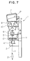
- a yarn package is formed by, for example, an auto-winder as shown in Figure 7.
- a groove 9 for traversing the yarn Y is formed in outer peripheral surface of the traverse drum 8 and an end missing prevention cover 10 is arranged in front of that.
- a package side yarn end grasping means 11 called a suction mouth and a yarn supply bobbin side yarn end grasping means 12 called a suction pipe for guiding respectively the yarn from the package and the yarn from the yarn supply bobbin to the yarn piecing device 6 by rotational movement are arranged.
- any defects in the yarn Y are removed by the slub catcher 5 of the winding unit 1 and while any imperfection appearing on the surface of the wound package P can be discovered, if a defective place inside the package is generated by an inappropriate winding during formation of the package, that defective package will not be discovered unless the package is used for the next process and unwound.
- This inspection means may be a yarn detection sensor that detects the existence of a yarn positioned outside the outermost layer of the package.
- this yarn detection sensor prefferably be arranged so that the detecting light passes close to the contact point of the package and the drive drum in contact with and rotating this package.
- the yarn detection sensor prefferably be arranged so that the decting light passes along the side where the yarn is introduced onto the package.
- the yarn detection sensor prefferably be formed so as to only operate when winding restarts at times of yarn piecing.
- winding of the package prefferably stopped when the package is detected to be abnormal by the inspection means.
- an illuminating element and light receiving element prefferably be positioned so that the detecting light of the yarn detection sensor passes at an angle from a position close to the drive drum to a position separated from the drive drum.
- Figure 1 is a perspective view showing a first embodiment of the present invention.
- Figure 2 is a side view of Figure 1.
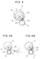
- Figure 3 is a side view for describing the movements of Figure 2.
- Figure 4 is a side view for describing other movements of Figure 2.
- Figure 5 is a side view for describing further movements of Figure 2.
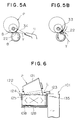
- Figure 6 is a front view showing a second embodiment of the present invention.
- Figure 7 is a front view showing the entire structure of the auto-winder.
- Figure 8 is a perspective view of a third embodiment of the present invention.
- Figures 1 and 2 show the application of a package quality inspection device being a first embodiment of the present invention on an auto-winder.
- a plurality of units of auto-winders are arranged in series on a winding unit 1 as shown in Figure 7.
- This quality inspection device is provided on each winding unit with an inspection means for inspecting a package P during the winding process and is arranged with a yarn detection sensor 22 as this inspection means that senses whether or not a yarn exists on the outer side of the regular outermost layer 21 of the cone shaped package P.
- the package P is formed by the winding of yarn Y on a winding tube B.
- the winding process is the process whereby the package P is formed by the winding of yarn Y on the winding tube B and includes the stage of winding the yarn Y during yarn piecing.
- the regular outermost layer 21 of the package P is the outermost layer of the yarn layer defined by a circle with the axis C of the package P as the center and having a radius from that center to the contact point 25 between the package P and drive drum 8.
- the radius of regular outermost layer 21 of the package P naturally differs in the axial direction of the package P.
- the yarn detection sensor 22 comprises a light emitting element 23 that emits laser light or the like for detection and a light receiving element 24 arranged opposite the light emitting element 23 and is arranged such that the detection light L from the light emitting element 23 passes close to the point of contact 25 (tangent) of the package P and drive drum (traverse drum) 8 for rotating the package P by friction contact. More specifically, the light detection sensor 22 is arranged such that the detection light L passes close to the drive drum 8 and regular outermost layer 21 of the package P or moreover, the position that does not contact the periphery of the outermost layer 21 and drive drum 8. The reason that yarn detection sensor 22 is arranged so that the detection light L passes close to the contact point 25 is because the position of the detection light L with respect to the outermost layer 21 does not change even if the winding diameter of the package P increases.
- the yarn detection sensor 22 is arranged such that the detection light L passes along the side (front side of the winding unit) F where the yarn Y is introduced onto the package P.
- package P errors severe, waste yarn, lifted yarn
- the detection of double yarn end finding and end missing is possible as described later.
- the package P is supported on the cradle arm (package support mechanism) 7 such that the contact point 25 retracts slightly with increases in the winding diameter but naturally, it is preferable to support the package P by the cradle arm 7 such that the contact point 25 does not change even if the winding diameter changes.
- the original objective of the inspection means is the inspection of the surface (outer most layer) 21 of the package P and as a result, it is important for the detection light L to pass close to the outermost layer 21 of the package P.
- the detection light L from this kind of light emitting element 23 is parallel with the contact point 25 (tangent) and is arranged so as to be in a detection state (ON) when this detection light L is cut off by an abnormality such as yarn outside of outermost layer 21 or the like.
- the yarn Y is wound on the surface of the package P while inserted and being traversed by the traverse groove 9 of the drive drum 8. Due to this, there is no detection of the yarn Y by the yarn detection sensor 22 even if the detection light L passes close to the peripheral surface of the drive drum 8.
- the light emitting element 23 is mounted on the upper surface of the main body frame 35 of the winding unit 1 via a bracket 26 and the light receiving element 24 is mounted via a bracket 28 on a cover 27 arranged over the front side F of the drive drum 8.
- the cover 27 comprises a plate having an arc-shaped cross section arranged close to the peripheral surface of the drive drum 8 and prevents end missing.
- the end of the side of the cover 27 furthest from the main body frame 35 is bent such that it follows the outer periphery of the axial end surface of the drive drum 8 and the bracket 28 is mounted on this bent part 29.
- the cradle arm 30 that supports the package P has a point being a center of rotation on the rear side R of the winding unit 1 and as the position of the contact point 25 hardly changes even if the winding diameter increases and there is no large movement of the positioning of the package surface near the contact point 25, the yarn detection sensor 22 is always able to detect whether there are abnormalities or not under the same conditions even if its position is fixed.
- the support system of the yarn detection sensor 22 may be extremely simple as with the brackets 26, 28 as shown in the drawings. However, if the yarn detection sensor 22 is too close to the package P surface, there is the chance of it detecting the fluff of the outermost layer 21 thus it should be separated from the surface by a predetermined minute distance.
- the yarn detection sensor 22 is connected to the slub catcher 5 (refer to Figure 7). If an abnormality is detected, the yarn Y may be immediately cut by a cutter attached to the slub catcher 5 or a cutter arranged elsewhere whereby the package P is separated from the drive drum 8 by the raising of the cradle arm 30 and the stoppage of the rotation of the package P by the application of a brake. Simultaneous with this, an alarm (lamp 31) of the winding unit 1 is emitted and the operator called in order to quickly restore operations.
- the inspection of the package P during the entire winding process can be achieved by the operation of the yarn detection sensor 22 from the time when winding starts (drum start) including the yarn piecing time and a stoppage of the winding can be performed immediately if disruptions of the package surface or the like are discovered.
- tension breakage where a yarn cut due to tension changes or the like winds once again onto the surface of the package P
- lifted yarn where the yarn is lifted from the outermost layer 21 of the package P due to contact pressure or tension
- the yarn detection sensor 22 is arranged on the side F where yarn is guided onto the package P (front side of the winding unit 1), abnormalities on the package P become easier to detect due to the following reason.
- Double yarn end finding is when the yarn end gripping means (suction mouth 11) pulls two yarns (the correct yarn Y and a yarn part 33 already wound on the package P) from the package P during yarn piecing as shown in Figure 4A.
- the yarn piecing device 6 determines a yarn end finding miss to have occurred and yarn piecing (the restart of winding) is not carried out.
- the yarn piecing device 6 executes normal yarn piecing operations and when winding is restarted, the other pulled yarn 33 is wound onto the package P and causes a defective product.
- the yarn part 33 wound at this time is quickly detected by the yarn detection sensor 22 as it is facing from the front side F of the winding unit 1 towards the package P surface.
- the suction mouth 11 finds the yarn 34 which has end missed together with the correct yarn Y during yarn piecing, similar to double yarn end finding, the yarn detection sensor 22 is able to detect this end missed yarn 34.
- the yarn detection sensor 22 is operated only when winding restarts (immediately after yarn piecing). In short, by the detection not occurring when the suction mouth 11 performs the yarn picking operation, erroneous operations where the yarn Y correctly pulled from the package P by the suction mouth 11 or the tip of the suction mouth 11 is detected by the yarn detection sensor 22 can be prevented.
- the inspection means of the present invention is able to prevent defects inside the package which could not be discovered by conventional processes by the reliably detection of the phenomenon being the causes of such and the generation of defective products in the package production process can be completely stopped by the simultaneous application of removal of yarn defects by the slub catcher 5 and post-winding surface inspection. In short, an increase in package quality can be achieved.
- a light sensor which filters light through a slit or the like may be used as the yarn detection sensor 22.
- any kind of sensor including those other than light may be used.
- the yarn detection sensor 22 is described as fixed near the front side F of the contact point 25 but, for example, it may be arranged above or behind the package P and inspection of the surface of the package P may be performed by moving it in the radial direction of the package P as the winding diameter increases.
- the yarn inspection means is not limited to a yarn detection sensor and may inspect the package P by imaging or the like.
- the package P may be cheese shaped and is not limited to a cone shape.
- FIG. 6 shows a second embodiment of the present invention.
- This second embodiment of the package quality inspection device differs when compared to the previously described first embodiment of the quality inspection device in the positioning of a light emitting element 124 and a light receiving element 123 wherein the detection light L of a yarn detection sensor 122 passes at an angle from a position close to a drive drum 108 to position far from it, the unification of the light emitting element 124 and light receiving element 123 by a bracket 128, the positioning of the light emitting element 124 on the small diameter side of a cone shaped package P, and the positioning of the light emitting element 124 on the free end side of the drive drum 108 held by one side only.
- the detection light L of a yarn detection sensor 122 passes at an angle from a position close to a drive drum 108 to position far from it, the unification of the light emitting element 124 and light receiving element 123 by a bracket 128, the positioning of the light emitting element 124 on the small diameter side of a cone shaped package P,
- the objective of the inspection means is the inspection of the surface (outer most layer) 121 of the package P and as a result, it is important for the detection light L to pass close to the outermost layer 121 of the package P. Due to this, it is preferable for the detection light L from the light emitting element 124 to be roughly parallel with a tangent 125 but as detection light reflected by the surface of the drive drum 108 is dispersed, the light emitting element 124 is positioned closer to the drive drum 108 than the light receiving element 123 so that the detection light L is slanted slightly with respect to the tangent 125 as shown in Figure 6.
- the yarn detection sensor 122 is arranged so as to be in a detection state (ON) when this detection light L is cut off by an abnormality such as yarn outside of outermost layer 21 or the like.
- the detection light L from the light emitting element 124 has directivity, the detection light L is dispersed and if it enters the light receiving element 123 by reflecting off the smooth surface of the drive drum 108 made of metal without being cut off by an abnormality, a detection state is not caused even if an abnormality exists.
- the detection light L from the light emitting element 124 to the light receiving element 123 is slanted slightly with respect to the tangent 125.
- the light emitting element 124 and light receiving element 123 are linked so as to be one unit by the bracket 128.
- the bracket 128 spanning the drive drum 108 in the axial direction on the outside of the cover (27 of Figure 1) arranged on the front side F of the drive drum 108 is mounted on the main body frame 135 of the winding unit 101 and the light emitting element 124 and light receiving element 123 are arranged either side of that bracket 128.
- the cover 27 is a plate having an arc-shaped cross section arranged in close proximity to the peripheral surface of the drive drum 8 (108) and prevents end missing.
- the bracket 128 comprises a connector part spanning both ends of the drive drum 108 and following the lower end of the cover (27 of Figure 1), a standing part positioned on each end of the drive drum 108 and which projects from the curve of the cover (27 of Figure 1), and a seat part for fixing the light emitting element 124 and light receiving element 123.
- the positioning of the light emitting element 124 and light receiving element 123 may be on either side of the drive drum 108 from the point of linear properties and symmetrical properties of the light but in the present embodiment, the light emitting element 124 is positioned on the small diameter side of of the package P. This positioning is particularly convenient for detection of end missing.
- the light emitting element 124 is positioned on the small diameter side of of the package P utilizing the characteristic whereby end missing easily occurs on the small diameter side of the package P and the characteristic whereby sensitivity to yarn is higher at a position closer to the light emitting element 124 than a position far from it as the luminous flux of the detection light L from the light emitting element 124 gradually disperses. Due to this, end missing is reliably detected.
- the light emitting element 124 is positioned on the free end of the drive drum 108.
- the drive drum 108 is supported on one side only by the main body frame 135 of the winding unit 101, the light receiving element 123 is positioned on this fixed side and the light emitting element 124 is positioned on the opposite free side.
- the main body frame 135 would be an obstacle in order to allow one part of the main body of the light emitting element 124 to be hidden by the drive drum 108.
- the positioning of the light emitting element 124 becomes free and mounting is simplified.
- the light emitting element 124 may be positioned on the small diameter side of the package P and on the free side of the drive drum 108.
- FIG 8 shows a third embodiment of the present invention.
- a light emitting device 224 of a third embodiment of the present invention is formed as a cylindrical housing 241, contains a light emitting IC being a light emitting element 224a in the base of that housing 241 and is arranged in the housing 241 with a spherical slit (first aperture) 242 that restricts the luminous flux from the light emitting IC to a round shape and a flat rectangular slit (second aperture) 243 that restricts that luminous flux to a flat shape.
- the light emitting IC emits infrared light or visible red light and a convex lens is not attached to that light emitting part.
- the diameter of the spherical slit 242 is 0.5-1mm and the short side of the rectangular slit 243 is 0.2-0.5mm. These dimensions are determined by the count (thickness) of the yarn Y and the detection distance.
- the light receiving element 223a of the light receiving device 223 is a high sensitivity light receiving IC.
- the reason for restricting the luminous flux by the slit is not only so that the scattering of detection light L to the surface of the drive drum 208 can be prevented but also due to the fact that, if the luminous flux from the light emitting element 224a is greater than the thickness of the yarn Y, the difference in the amount of received light due to the presence or absence of a yarn is reduced but by restricting the luminous flux, the difference is the amount of received light is increased by the yarn effectively interrupting the light. However, if the luminous flux is restricted too much, the amount of received light by which the light receiving element 223a effectively operates can not be maintained. Thus the aforementioned slit dimensions are determined.
- the reason for the arrangement of a flat rectangular slit 243 is because, when the luminous flux is restricted to a flat shape and the yarn cuts across that flat luminous flux, if the yarn cuts across when parallel with that flat luminous flux the difference in the amount of received light due to the presence or absence of yarn becomes conspicuous.
- the luminous flux restricted to a flat shape has a cross section 244 as shown by the striped section and produces a difference in the amount of received light if the propotion of area represented by the yarn with respect to that cross section 244 is great. Accordingly, in order to produce an effective construction for yarn detection when winding restarts after a double yarn end finding or end missing, it is preferable for the long side of the rectangular slit 243 is be parallel in the direction of tha yarn pulled from the package P.
- the reason for not attaching a convex lens to the light emitting IC forming the light emitting element 224a is because, by restricting the converged light to a flat shape by a convex lens, the light axis of the light emitting device is greatly displaced due to the slight deviation of the directivity of a convex lens. Further, instead of a convex lens attached to the light emitting IC, by converging by the arrangement of other optics having a precise directivity means that comprising the yarn detection sensor 222 as a cheap structure is impossible. Accordingly, the present embodiment does not converge the dispersed light from the light emitting part of the light emitting IC but directly shines it into spherical and rectangular slits 242, 243.
- the axis of light is determined only from the positional relationship between the light emitting element 224a and slit 242, 243 and no light axis variance occurs if the light receiving element 223a is arranged along the light axis of the light emitting element 224d.
- the direction (long side direction) in which the aforementioned rectangular slit 243 is extended lengthways is a direction being approximately parallel with respect to abnormal yarn 34 shown in Figure 5B.
- the inspection means is a yarn detection sensor that detects the existance of yarn positioned outside the outermost layer of the package thus if disruptions to the outermost surface of the package occur, these can be detected immediately by a yarn detection sensor.
- the yarn detection sensor is arranged such that detection light passes close to the contact point of the package and the drive drum that rotates the package by contact with the package thus as the relative positional relationship between the position through which detection light of the yarn detection sensor passes and the position of the outermost layer of the package does not change depending on the diameter of the package, the yarn detection sensor may be fixed in a uniform position.
- the yarn detection sensor is arranged such that detection light passes along the side where the yarn is introduced onto the package thus not only are package abnormalities easy to detect but also double yarn end finding and end missing may be detected when winding restarts during yarn piecing.
- the yarn detection sensor only operates at the restart of winding during yarn piecing thus double yarn end finding and the like can be sensed without the erroneous detection of the yarn end grasping means.
- the yarn detection sensor has a light emitting element and light receiving element and the light emitting element and light receiving element are positioned such that the detection light of the yarn detection sensor passes at an angle from a position close to the drive drum to a position far from the drive drum thus erroneous operations can be prevented by the removal of reflection of detection light by the drive drum.
- the aperture for restricting the luminous flux is arranged in the light emitting device, there is no danger of the light being scattered even if light having high directivity is used and erroneous detection can be prevented. Furthermore, as the aperture is a flat slit extending approximately parallel with the direction in which abnormal yarn pulled from the package extends, any arising yarn abnormalities can be reliably detected. Yet further, as the light from the light emitting body of the light emitting device is directly restricted, the optical axis of the light emitting device and light receiving device can be easily aligned.
Landscapes
- Engineering & Computer Science (AREA)
- Quality & Reliability (AREA)
- Filamentary Materials, Packages, And Safety Devices Therefor (AREA)
- Spinning Or Twisting Of Yarns (AREA)
- Investigating Materials By The Use Of Optical Means Adapted For Particular Applications (AREA)
Applications Claiming Priority (3)
| Application Number | Priority Date | Filing Date | Title |
|---|---|---|---|
| JP14939496 | 1996-06-11 | ||
| JP8149394A JP2877079B2 (ja) | 1996-06-11 | 1996-06-11 | パッケージの品質監視装置 |
| JP149394/96 | 1996-06-11 |
Publications (3)
| Publication Number | Publication Date |
|---|---|
| EP0812794A2 true EP0812794A2 (fr) | 1997-12-17 |
| EP0812794A3 EP0812794A3 (fr) | 1999-01-07 |
| EP0812794B1 EP0812794B1 (fr) | 2002-08-07 |
Family
ID=15474176
Family Applications (1)
| Application Number | Title | Priority Date | Filing Date |
|---|---|---|---|
| EP19970108327 Expired - Lifetime EP0812794B1 (fr) | 1996-06-11 | 1997-05-22 | Dispositif pour l'inspection de la qualité de bobines |
Country Status (4)
| Country | Link |
|---|---|
| EP (1) | EP0812794B1 (fr) |
| JP (1) | JP2877079B2 (fr) |
| CN (1) | CN1167725A (fr) |
| DE (1) | DE69714519T2 (fr) |
Cited By (1)
| Publication number | Priority date | Publication date | Assignee | Title |
|---|---|---|---|---|
| CN106629248A (zh) * | 2016-11-28 | 2017-05-10 | 江苏悦达家纺有限公司 | 基于实时检测的络筒工艺用络卷筒及其检测方法 |
Families Citing this family (8)
| Publication number | Priority date | Publication date | Assignee | Title |
|---|---|---|---|---|
| DE102005009159B4 (de) * | 2005-02-25 | 2021-08-12 | Trützschler GmbH & Co Kommanditgesellschaft | Vorrichtung an einer Spinnereivorbereitungsmaschine zur Überwachung mindestens eines Faserbandes |
| DE102005009157B4 (de) * | 2005-02-25 | 2019-05-09 | Trützschler GmbH & Co Kommanditgesellschaft | Vorrichtung an einer Spinnereivorbereitungsmaschine z.B. Karde, Krempel, Strecke o. dgl. zur Überwachung von Fasermaterial |
| JP2011016630A (ja) * | 2009-07-09 | 2011-01-27 | Murata Machinery Ltd | 繊維機械 |
| DE102014008574A1 (de) * | 2014-06-11 | 2015-12-17 | Saurer Germany Gmbh & Co. Kg | Textilmaschine mit Spulvorrichtungen |
| FR3033322B1 (fr) * | 2015-03-06 | 2019-09-13 | Saurer Germany Gmbh & Co. Kg | Procede et dispositif de detection de la fin de devidage d'un element filiforme |
| CN108035019A (zh) * | 2017-11-13 | 2018-05-15 | 海盐县金超化纤有限公司 | 一种并纱加捻一体装置 |
| CN107938041A (zh) * | 2017-11-13 | 2018-04-20 | 海盐县金超化纤有限公司 | 一种用于锦纶丝加捻的加捻装置 |
| CN108083008A (zh) * | 2017-11-13 | 2018-05-29 | 海盐县金超化纤有限公司 | 一种多股并纱装置 |
Citations (4)
| Publication number | Priority date | Publication date | Assignee | Title |
|---|---|---|---|---|
| JPH05178541A (ja) * | 1991-12-24 | 1993-07-20 | Toyobo Co Ltd | 合成繊維糸条の巻取装置 |
| EP0650915A1 (fr) * | 1993-10-29 | 1995-05-03 | Zellweger Luwa Ag | Dispositif pour contrôler la qualité de l'enroulement de bobines de fil et utilisation du dispositif dans un bobinoir ou un métier à filer |
| DE4430566A1 (de) * | 1993-08-31 | 1995-07-06 | Barmag Barmer Maschf | Verfahren zum Aufwickeln eines Fadens einer geradzylindrischen Kreuzspule |
| EP0749929A2 (fr) * | 1993-11-15 | 1996-12-27 | Maschinenfabrik Rieter Ag | Méthodes et appareil pour le bobinage de filaments |
-
1996
- 1996-06-11 JP JP8149394A patent/JP2877079B2/ja not_active Expired - Fee Related
-
1997
- 1997-02-27 CN CN 97100796 patent/CN1167725A/zh active Pending
- 1997-05-22 DE DE1997614519 patent/DE69714519T2/de not_active Expired - Lifetime
- 1997-05-22 EP EP19970108327 patent/EP0812794B1/fr not_active Expired - Lifetime
Patent Citations (4)
| Publication number | Priority date | Publication date | Assignee | Title |
|---|---|---|---|---|
| JPH05178541A (ja) * | 1991-12-24 | 1993-07-20 | Toyobo Co Ltd | 合成繊維糸条の巻取装置 |
| DE4430566A1 (de) * | 1993-08-31 | 1995-07-06 | Barmag Barmer Maschf | Verfahren zum Aufwickeln eines Fadens einer geradzylindrischen Kreuzspule |
| EP0650915A1 (fr) * | 1993-10-29 | 1995-05-03 | Zellweger Luwa Ag | Dispositif pour contrôler la qualité de l'enroulement de bobines de fil et utilisation du dispositif dans un bobinoir ou un métier à filer |
| EP0749929A2 (fr) * | 1993-11-15 | 1996-12-27 | Maschinenfabrik Rieter Ag | Méthodes et appareil pour le bobinage de filaments |
Non-Patent Citations (1)
| Title |
|---|
| PATENT ABSTRACTS OF JAPAN vol. 017, no. 603 (M-1505), 5 November 1993 -& JP 05 178541 A (TOYOBO CO LTD), 20 July 1993 * |
Cited By (1)
| Publication number | Priority date | Publication date | Assignee | Title |
|---|---|---|---|---|
| CN106629248A (zh) * | 2016-11-28 | 2017-05-10 | 江苏悦达家纺有限公司 | 基于实时检测的络筒工艺用络卷筒及其检测方法 |
Also Published As
| Publication number | Publication date |
|---|---|
| DE69714519D1 (de) | 2002-09-12 |
| EP0812794A3 (fr) | 1999-01-07 |
| CN1167725A (zh) | 1997-12-17 |
| JP2877079B2 (ja) | 1999-03-31 |
| DE69714519T2 (de) | 2003-04-17 |
| JPH09328256A (ja) | 1997-12-22 |
| EP0812794B1 (fr) | 2002-08-07 |
Similar Documents
| Publication | Publication Date | Title |
|---|---|---|
| EP0812794A2 (fr) | Dispositif pour l'inspection de la qualité de bobines | |
| EP2354069A2 (fr) | Machine de renvideur de fil | |
| EP2361867A2 (fr) | Machine de renvideur de fil | |
| US5701729A (en) | System for forming elastomeric core/staple fiber wrap yarn using a spinning machine | |
| US5605296A (en) | Method and apparatus for winding a yarn | |
| EP2426482B1 (fr) | Dispositif de surveillance de matériau textile et appareil d'enroulement de fils | |
| EP2905248B1 (fr) | Dispositif d'épissage de fil et machine d'enroulement de fils | |
| US5767963A (en) | Method and apparatus of detecting a yarn lap on a rotating roll | |
| EP2365115B1 (fr) | Machine de bobinage de fil avec rouleau intermédiaire accumulateur de fil | |
| US6533211B2 (en) | Method of operating a textile machine for producing cheeses | |
| US20030094083A1 (en) | Device and process for removing the defective end portions from yarn on a package fed to an automatic winder | |
| CN100542924C (zh) | 用于检测纱线的装置 | |
| JPH10182004A (ja) | パッケージ監視装置 | |
| JP2924835B2 (ja) | パッケージ監視装置 | |
| EP3934999B1 (fr) | Appareil et procédés pour détecter une queue de fouettement pendant un enroulement de fibre | |
| CN111039088A (zh) | 供制造卷绕筒子的纺织机用的纱管 | |
| CN107539841A (zh) | 纤维机械 | |
| JP4177088B2 (ja) | 線状体の残量検出方法 | |
| US20020109031A1 (en) | Apparatus on a direct roving winder for contactless detection of the actual diameter of the roving package and a direct roving winder with such an apparatus and also a method for controlling a roving winder and a method for controlling a spinning appliance | |
| JPH07118963A (ja) | ローラへの糸巻付き検出装置 | |
| JP2000016703A (ja) | ローラへの糸巻付検出装置 | |
| EP0748886A2 (fr) | Système pour fabriquer un fil à âme élastique à fibres discontinues en utilisant un métier à filer | |
| JP2593963Y2 (ja) | 糸切れ検出機能付糸シート搬送装置 | |
| JPH0640662A (ja) | 自動ワインダのヤーンフィーラ | |
| JP2748146B2 (ja) | サイジング工程における糸切れ検知装置 |
Legal Events
| Date | Code | Title | Description |
|---|---|---|---|
| PUAI | Public reference made under article 153(3) epc to a published international application that has entered the european phase |
Free format text: ORIGINAL CODE: 0009012 |
|
| AK | Designated contracting states |
Kind code of ref document: A2 Designated state(s): DE IT |
|
| PUAL | Search report despatched |
Free format text: ORIGINAL CODE: 0009013 |
|
| AK | Designated contracting states |
Kind code of ref document: A3 Designated state(s): DE IT |
|
| 17P | Request for examination filed |
Effective date: 19990303 |
|
| 17Q | First examination report despatched |
Effective date: 19990607 |
|
| GRAG | Despatch of communication of intention to grant |
Free format text: ORIGINAL CODE: EPIDOS AGRA |
|
| GRAG | Despatch of communication of intention to grant |
Free format text: ORIGINAL CODE: EPIDOS AGRA |
|
| GRAH | Despatch of communication of intention to grant a patent |
Free format text: ORIGINAL CODE: EPIDOS IGRA |
|
| GRAH | Despatch of communication of intention to grant a patent |
Free format text: ORIGINAL CODE: EPIDOS IGRA |
|
| GRAA | (expected) grant |
Free format text: ORIGINAL CODE: 0009210 |
|
| AK | Designated contracting states |
Kind code of ref document: B1 Designated state(s): DE IT |
|
| REF | Corresponds to: |
Ref document number: 69714519 Country of ref document: DE Date of ref document: 20020912 |
|
| PLBE | No opposition filed within time limit |
Free format text: ORIGINAL CODE: 0009261 |
|
| STAA | Information on the status of an ep patent application or granted ep patent |
Free format text: STATUS: NO OPPOSITION FILED WITHIN TIME LIMIT |
|
| 26N | No opposition filed |
Effective date: 20030508 |
|
| REG | Reference to a national code |
Ref country code: DE Ref legal event code: R082 Ref document number: 69714519 Country of ref document: DE Representative=s name: WEICKMANN & WEICKMANN PATENTANWAELTE - RECHTSA, DE Ref country code: DE Ref legal event code: R082 Ref document number: 69714519 Country of ref document: DE Representative=s name: PATENTANWAELTE WEICKMANN & WEICKMANN, DE |
|
| PGFP | Annual fee paid to national office [announced via postgrant information from national office to epo] |
Ref country code: DE Payment date: 20160520 Year of fee payment: 20 |
|
| PGFP | Annual fee paid to national office [announced via postgrant information from national office to epo] |
Ref country code: IT Payment date: 20160524 Year of fee payment: 20 |
|
| REG | Reference to a national code |
Ref country code: DE Ref legal event code: R071 Ref document number: 69714519 Country of ref document: DE |