EP0811900A1 - Gas-regel- und -verteilungsanordnung für Druckgasbehälter - Google Patents
Gas-regel- und -verteilungsanordnung für Druckgasbehälter Download PDFInfo
- Publication number
- EP0811900A1 EP0811900A1 EP97401216A EP97401216A EP0811900A1 EP 0811900 A1 EP0811900 A1 EP 0811900A1 EP 97401216 A EP97401216 A EP 97401216A EP 97401216 A EP97401216 A EP 97401216A EP 0811900 A1 EP0811900 A1 EP 0811900A1
- Authority
- EP
- European Patent Office
- Prior art keywords
- valve
- gas
- assembly according
- tubular
- bell
- Prior art date
- Legal status (The legal status is an assumption and is not a legal conclusion. Google has not performed a legal analysis and makes no representation as to the accuracy of the status listed.)
- Granted
Links
Images


Classifications
-
- G—PHYSICS
- G05—CONTROLLING; REGULATING
- G05D—SYSTEMS FOR CONTROLLING OR REGULATING NON-ELECTRIC VARIABLES
- G05D16/00—Control of fluid pressure
- G05D16/04—Control of fluid pressure without auxiliary power
- G05D16/10—Control of fluid pressure without auxiliary power the sensing element being a piston or plunger
- G05D16/103—Control of fluid pressure without auxiliary power the sensing element being a piston or plunger the sensing element placed between the inlet and outlet
-
- F—MECHANICAL ENGINEERING; LIGHTING; HEATING; WEAPONS; BLASTING
- F17—STORING OR DISTRIBUTING GASES OR LIQUIDS
- F17C—VESSELS FOR CONTAINING OR STORING COMPRESSED, LIQUEFIED OR SOLIDIFIED GASES; FIXED-CAPACITY GAS-HOLDERS; FILLING VESSELS WITH, OR DISCHARGING FROM VESSELS, COMPRESSED, LIQUEFIED, OR SOLIDIFIED GASES
- F17C13/00—Details of vessels or of the filling or discharging of vessels
- F17C13/04—Arrangement or mounting of valves
-
- G—PHYSICS
- G05—CONTROLLING; REGULATING
- G05D—SYSTEMS FOR CONTROLLING OR REGULATING NON-ELECTRIC VARIABLES
- G05D16/00—Control of fluid pressure
- G05D16/04—Control of fluid pressure without auxiliary power
- G05D16/0402—Control of fluid pressure without auxiliary power with two or more controllers mounted in series
-
- G—PHYSICS
- G05—CONTROLLING; REGULATING
- G05D—SYSTEMS FOR CONTROLLING OR REGULATING NON-ELECTRIC VARIABLES
- G05D16/00—Control of fluid pressure
- G05D16/04—Control of fluid pressure without auxiliary power
- G05D16/10—Control of fluid pressure without auxiliary power the sensing element being a piston or plunger
- G05D16/101—Control of fluid pressure without auxiliary power the sensing element being a piston or plunger the controller being arranged as a multiple-way valve
-
- F—MECHANICAL ENGINEERING; LIGHTING; HEATING; WEAPONS; BLASTING
- F17—STORING OR DISTRIBUTING GASES OR LIQUIDS
- F17C—VESSELS FOR CONTAINING OR STORING COMPRESSED, LIQUEFIED OR SOLIDIFIED GASES; FIXED-CAPACITY GAS-HOLDERS; FILLING VESSELS WITH, OR DISCHARGING FROM VESSELS, COMPRESSED, LIQUEFIED, OR SOLIDIFIED GASES
- F17C2201/00—Vessel construction, in particular geometry, arrangement or size
- F17C2201/05—Size
- F17C2201/056—Small (<1 m3)
-
- F—MECHANICAL ENGINEERING; LIGHTING; HEATING; WEAPONS; BLASTING
- F17—STORING OR DISTRIBUTING GASES OR LIQUIDS
- F17C—VESSELS FOR CONTAINING OR STORING COMPRESSED, LIQUEFIED OR SOLIDIFIED GASES; FIXED-CAPACITY GAS-HOLDERS; FILLING VESSELS WITH, OR DISCHARGING FROM VESSELS, COMPRESSED, LIQUEFIED, OR SOLIDIFIED GASES
- F17C2201/00—Vessel construction, in particular geometry, arrangement or size
- F17C2201/05—Size
- F17C2201/058—Size portable (<30 l)
-
- F—MECHANICAL ENGINEERING; LIGHTING; HEATING; WEAPONS; BLASTING
- F17—STORING OR DISTRIBUTING GASES OR LIQUIDS
- F17C—VESSELS FOR CONTAINING OR STORING COMPRESSED, LIQUEFIED OR SOLIDIFIED GASES; FIXED-CAPACITY GAS-HOLDERS; FILLING VESSELS WITH, OR DISCHARGING FROM VESSELS, COMPRESSED, LIQUEFIED, OR SOLIDIFIED GASES
- F17C2205/00—Vessel construction, in particular mounting arrangements, attachments or identifications means
- F17C2205/03—Fluid connections, filters, valves, closure means or other attachments
- F17C2205/0302—Fittings, valves, filters, or components in connection with the gas storage device
- F17C2205/0323—Valves
- F17C2205/0329—Valves manually actuated
-
- F—MECHANICAL ENGINEERING; LIGHTING; HEATING; WEAPONS; BLASTING
- F17—STORING OR DISTRIBUTING GASES OR LIQUIDS
- F17C—VESSELS FOR CONTAINING OR STORING COMPRESSED, LIQUEFIED OR SOLIDIFIED GASES; FIXED-CAPACITY GAS-HOLDERS; FILLING VESSELS WITH, OR DISCHARGING FROM VESSELS, COMPRESSED, LIQUEFIED, OR SOLIDIFIED GASES
- F17C2205/00—Vessel construction, in particular mounting arrangements, attachments or identifications means
- F17C2205/03—Fluid connections, filters, valves, closure means or other attachments
- F17C2205/0302—Fittings, valves, filters, or components in connection with the gas storage device
- F17C2205/0338—Pressure regulators
-
- F—MECHANICAL ENGINEERING; LIGHTING; HEATING; WEAPONS; BLASTING
- F17—STORING OR DISTRIBUTING GASES OR LIQUIDS
- F17C—VESSELS FOR CONTAINING OR STORING COMPRESSED, LIQUEFIED OR SOLIDIFIED GASES; FIXED-CAPACITY GAS-HOLDERS; FILLING VESSELS WITH, OR DISCHARGING FROM VESSELS, COMPRESSED, LIQUEFIED, OR SOLIDIFIED GASES
- F17C2205/00—Vessel construction, in particular mounting arrangements, attachments or identifications means
- F17C2205/03—Fluid connections, filters, valves, closure means or other attachments
- F17C2205/0302—Fittings, valves, filters, or components in connection with the gas storage device
- F17C2205/0382—Constructional details of valves, regulators
- F17C2205/0385—Constructional details of valves, regulators in blocks or units
-
- F—MECHANICAL ENGINEERING; LIGHTING; HEATING; WEAPONS; BLASTING
- F17—STORING OR DISTRIBUTING GASES OR LIQUIDS
- F17C—VESSELS FOR CONTAINING OR STORING COMPRESSED, LIQUEFIED OR SOLIDIFIED GASES; FIXED-CAPACITY GAS-HOLDERS; FILLING VESSELS WITH, OR DISCHARGING FROM VESSELS, COMPRESSED, LIQUEFIED, OR SOLIDIFIED GASES
- F17C2205/00—Vessel construction, in particular mounting arrangements, attachments or identifications means
- F17C2205/03—Fluid connections, filters, valves, closure means or other attachments
- F17C2205/0388—Arrangement of valves, regulators, filters
- F17C2205/0394—Arrangement of valves, regulators, filters in direct contact with the pressure vessel
-
- F—MECHANICAL ENGINEERING; LIGHTING; HEATING; WEAPONS; BLASTING
- F17—STORING OR DISTRIBUTING GASES OR LIQUIDS
- F17C—VESSELS FOR CONTAINING OR STORING COMPRESSED, LIQUEFIED OR SOLIDIFIED GASES; FIXED-CAPACITY GAS-HOLDERS; FILLING VESSELS WITH, OR DISCHARGING FROM VESSELS, COMPRESSED, LIQUEFIED, OR SOLIDIFIED GASES
- F17C2221/00—Handled fluid, in particular type of fluid
- F17C2221/01—Pure fluids
- F17C2221/011—Oxygen
-
- F—MECHANICAL ENGINEERING; LIGHTING; HEATING; WEAPONS; BLASTING
- F17—STORING OR DISTRIBUTING GASES OR LIQUIDS
- F17C—VESSELS FOR CONTAINING OR STORING COMPRESSED, LIQUEFIED OR SOLIDIFIED GASES; FIXED-CAPACITY GAS-HOLDERS; FILLING VESSELS WITH, OR DISCHARGING FROM VESSELS, COMPRESSED, LIQUEFIED, OR SOLIDIFIED GASES
- F17C2227/00—Transfer of fluids, i.e. method or means for transferring the fluid; Heat exchange with the fluid
- F17C2227/04—Methods for emptying or filling
- F17C2227/048—Methods for emptying or filling by maintaining residual pressure
-
- Y—GENERAL TAGGING OF NEW TECHNOLOGICAL DEVELOPMENTS; GENERAL TAGGING OF CROSS-SECTIONAL TECHNOLOGIES SPANNING OVER SEVERAL SECTIONS OF THE IPC; TECHNICAL SUBJECTS COVERED BY FORMER USPC CROSS-REFERENCE ART COLLECTIONS [XRACs] AND DIGESTS
- Y10—TECHNICAL SUBJECTS COVERED BY FORMER USPC
- Y10T—TECHNICAL SUBJECTS COVERED BY FORMER US CLASSIFICATION
- Y10T137/00—Fluid handling
- Y10T137/7722—Line condition change responsive valves
- Y10T137/7781—With separate connected fluid reactor surface
- Y10T137/7793—With opening bias [e.g., pressure regulator]
- Y10T137/7808—Apertured reactor surface surrounds flow line
-
- Y—GENERAL TAGGING OF NEW TECHNOLOGICAL DEVELOPMENTS; GENERAL TAGGING OF CROSS-SECTIONAL TECHNOLOGIES SPANNING OVER SEVERAL SECTIONS OF THE IPC; TECHNICAL SUBJECTS COVERED BY FORMER USPC CROSS-REFERENCE ART COLLECTIONS [XRACs] AND DIGESTS
- Y10—TECHNICAL SUBJECTS COVERED BY FORMER USPC
- Y10T—TECHNICAL SUBJECTS COVERED BY FORMER US CLASSIFICATION
- Y10T137/00—Fluid handling
- Y10T137/8158—With indicator, register, recorder, alarm or inspection means
- Y10T137/8225—Position or extent of motion indicator
- Y10T137/8275—Indicator element rigidly carried by the movable element whose position is indicated
-
- Y—GENERAL TAGGING OF NEW TECHNOLOGICAL DEVELOPMENTS; GENERAL TAGGING OF CROSS-SECTIONAL TECHNOLOGIES SPANNING OVER SEVERAL SECTIONS OF THE IPC; TECHNICAL SUBJECTS COVERED BY FORMER USPC CROSS-REFERENCE ART COLLECTIONS [XRACs] AND DIGESTS
- Y10—TECHNICAL SUBJECTS COVERED BY FORMER USPC
- Y10T—TECHNICAL SUBJECTS COVERED BY FORMER US CLASSIFICATION
- Y10T137/00—Fluid handling
- Y10T137/8593—Systems
- Y10T137/87917—Flow path with serial valves and/or closures
- Y10T137/88046—Biased valve with external operator
Definitions
- the present invention relates to a gas control and distribution assembly, adapted to be connected to a tank containing pressurized gas, for example a gas for medical use such as oxygen, of the type comprising a body in which is formed a gas inlet passage from the tank, containing an isolation valve exposed to gas under high pressure, a pressure regulator, means for selecting and regulating the flow rate through at least one outlet for gas at reduced pressure, this assembly also comprising a tubular member for controlling the isolation valve covering the body.
- a gas control and distribution assembly adapted to be connected to a tank containing pressurized gas, for example a gas for medical use such as oxygen, of the type comprising a body in which is formed a gas inlet passage from the tank, containing an isolation valve exposed to gas under high pressure, a pressure regulator, means for selecting and regulating the flow rate through at least one outlet for gas at reduced pressure, this assembly also comprising a tubular member for controlling the isolation valve covering the body.
- a control assembly of this type is described in document EP-A-0 629 937.
- the tubular member contains a sub-assembly movable longitudinally by the rotation of the tubular control member by means appropriate cutouts forming cams, and this movement in turn controls the axial movement of the isolation valve.
- This structure is relatively complex and therefore expensive.
- the residual compressed gas discharge valve disposed laterally to this structure, can only have a small diameter. Correlatively it must be actuated by a large pressure variation (2 to 3x10 5 Pa), which involves the obligation to carry out a laborious adjustment of this valve. Its manufacturing cost is also relatively high, due to the number of parts and the machining operations required. Also in this previous control assembly, the through holes of the flow selector disc are offset longitudinally from the low pressure gas outlet and must be made by chemical means due to their very small diameter (of the order of 0 , 1mm for the first hole), these chemical drilling means being very expensive. Finally, this technology requires an extremely tight drilling tolerance for these holes (on the order of a micron).
- the object of the invention is to propose a gas control and distribution assembly of the aforementioned type, of simplified construction and of reduced costs.
- the isolation valve is constituted by a drawer movable transversely in a housing of the body and whose opposite ends cooperate directly with curved guide ramps formed by the tubular control member and profiled so that a rotation of the tubular member causes the drawer to move in translation transversely to the axis, in one direction or in the opposite direction in the direction of rotation of the tubular member.
- Such a system with a transversely sliding drawer and cooperating directly with the tubular control member is notably simpler and of a lower manufacturing cost than the axially sliding sub-assembly for controlling the isolation valve, throughout the above-mentioned document. .
- the assembly comprises means for prohibiting the selection of a low pressure gas flow as long as the isolation valve is closed, and conversely for prohibiting the closing of the isolation valve as long as the flow selection means are open.
- the assembly includes a discharge valve mounted in the body coaxially with the regulator, the valve and the regulator being housed in a recess in the body communicating with the outside through openings formed in the body and in the tubular control member of the isolation valve.
- the assembly further includes a filling valve comprising a cage movable axially in a stepped bore and internally defining a chamber of the same internal diameter as a portion of reduced diameter of the stepped bore and receiving a part of the valve element carrying the seal to receive, and shelter, the latter when the valve element moves from its closed position.
- a filling valve comprising a cage movable axially in a stepped bore and internally defining a chamber of the same internal diameter as a portion of reduced diameter of the stepped bore and receiving a part of the valve element carrying the seal to receive, and shelter, the latter when the valve element moves from its closed position.
- the annular seal is placed sheltered from the tubular part before the effective opening of the valve element and is thus mechanically and thermally protected by the cage against the undesirable effects of the introduction of particles. and the high temperature resulting from the rapid adiabatic compression of the filling gas when the circuits between the source of pressurized gas and the internal volume of the tank are opened.
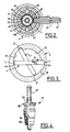
- the gas control and distribution assembly shown in the drawings is adapted to be connected to a reservoir (not shown), or more particularly a bottle containing gas under high pressure, in particular a gas for medical use, typically oxygen.
- This control assembly comprises an elongated body 1, a lower end 2 of which is threaded so that it can be screwed into a corresponding tapped opening of the inlet to the tank, and in which a longitudinal bore 3 for entering the tank gas is formed.
- an isolation valve 4 exposed to the gas under high pressure reaching through the bore 3, a pressure regulator 5 disposed downstream of the slide 4, and a lateral connection 6 for medium pressure gas outlet .
- the assembly also includes a second expansion stage 7 placed downstream of the regulator 5 and situated opposite a connection 8 for the outlet of gas at reduced pressure (that is to say at a pressure higher than atmospheric pressure) , a device 9 for selecting and regulating the flow of low pressure gas through the connector 8, and a tubular member 11 covering a tubular upper part of the body 1 and of the same longitudinal axis XX as the latter, and containing the isolation valve 4, the regulator 5, the second expansion stage 7 and the flow selector 9.
- the means for filling the reservoir 1 comprise a valve 12 mounted in a transverse stepped bore of the body 1 between the threaded end 2 and the drawer 4, this valve being urged in the closed position by a spring 13 bearing on a porous filter 14 bridging the bore 3.
- the valve 12 opens into a lateral inlet nozzle 15 in which is formed a thread 16 for screwing a connection fitting to a filling container, this nozzle having an inlet flange 17 whose diameter is less than that of the internal thread 16 and prohibiting the screwing of any fitting which would have the same diameters and not as the internal thread 16, guaranteeing the filling of the tank and the adequacy of its content during its use. Indeed filling can only be carried out by a suitable device, such as that described in document FR-A-2 726 346.
- the tubular control member 11 covers the upper part of the body 1 and comprises, at its lower end facing the isolation valve formed by the drawer 4, two opposite ramps or surfaces forming cams 18, 19, formed on its inner wall.
- the ramps 18, 19 are in contact with the rounded opposite ends 4a, 4b protruding from the body 1 of the slide 4, which is disposed orthogonally to the longitudinal axis XX of the body 1 and the tubular member 11.
- the ramps 18, 19 are connected to each other and extend angularly over the greater part of the inner circumference of the end of the tubular member 11, their opposite ends A, D, being separated by an inner angular projecting part 21.
- the opposite ends 4 a , 4 b of the drawer 4 are rounded so as to facilitate their sliding on the ramps 18, 19, which are profiled so that a rotation of the member tubular 11 causes the slide 4 to move transversely in one direction or in the opposite direction depending on the direction of rotation of the tubular member 11, by opening or correspondingly closing the isolation valve 4.
- the ramps 18, 19 are diametrically opposite and that while the radius of curvature of the ramp 18 decreases from its end A to its end B, the radius of curvature of the ramp 19 increases by its end C, diametrically opposite the end A, to its end D, diametrically opposite the end B of the ramp 18.
- the adjacent ends B and C of the ramps are connected by a circular sector of substantially constant radius. It is understood that under these conditions, the rotation of the member 11 causes a transverse translation of the drawer 4 in its housing 26 of the body 1 in one of the two directions indicated by the arrows F1, F2.
- the second position 4.1 is shown of the drawer 4 angularly offset from its first position with its ends 4 a , 4 b abutting against the ends of the shoulder 21, at points B and D. But in reality the position 4.1 is shifted only in translation relative to the position 4 since it is the member 11 which rotates about its axis XX, and not the drawer 4.
- the drawer 4 comprises a central part 23, carrying a seal and sliding in leaktight manner in a seal 24 and in a socket 25 mounted in a transverse stepped bore of the body 1, and which is followed by a section 22 of smaller diameter, located opposite the outlet of the inlet bore 3, itself connected to a flange 27, carrying a seal and of the same diameter as the central part 23 and sliding in a reduced diameter portion 26 of the transverse bore where the inlet bore opens 3.
- the sleeve 25 forms an interior chamber 10 and is pierced with radial holes 28 allowing gas to pass from chamber 10 into an annular peripheral chamber 29 and from there into an axial bore 31 of the body 1 opening into an axial chamber 32 which itself communicates with an upper chamber 33 of larger diameter, formed coaxially in the upper part of the body 1.
- the chambers 32 and 33 contain the upstream regulator 5 as well as the exhaust gas discharge valve 34, which are arranged as follows.
- the regulator 5 comprises a cylindrical piston tail 35, one end of which is slidably engaged in the lower chamber 32 and has a transverse bore 36 opening into the chamber 32, which also communicates with the outlet channel 37 of the connector 6.
- the bore 36 communicates with a longitudinal channel 38 of the central tail 35, opening at the opposite end of the latter, which is extended by a piston 39 slidably mounted in leaktight manner in the upper chamber 33.
- a second transverse bore 41 whose opposite ends open into an intermediate space 42 delimited by the bottom of the chamber 33 and a valve 43 mounted coaxially on the central stem 35.
- a seal 44 is interposed between the underside of the valve 43 and the bottom facing the chamber 33.
- the valve 43 is urged to bear on the seal 44, against the bottom by a res helical outlet 45 coaxial with the valve 43 and with the tubular tail 35 of the regulator 5.
- the piston 39 slides in leaktight manner in the chamber 33 thanks to a peripheral seal 46.
- the valve device 34 for evacuating the residual pressure at the pressure reducer 5 is completed by radial bores 47, 48 formed respectively in the tubular wall 49 of the upper part of the body 1 and in the wall of the tubular member 11 .
- the control and distribution assembly further comprises, downstream longitudinally of the regulator 5 and in the direction of the upper end of the member 11 opposite to the drawer 4, a second expansion stage 7, located at the level of the nozzle 8 low pressure, which will now be described.
- This system of second expansion, or downstream expansion comprises a device 51 with expansion valve (FIGS. 1 and 4) mounted in an axial tubular projection 52 of a tubular body 53 engaged inside the body 1 and on a end 54 from which the tubular member 11 fits.
- This body 53 is fixed in rotation and in axial translation, and contains a bell 55 inside which extends the axial projection 52.
- a piston 56 is slidably mounted tightly inside the chamber 57 of the bell 55, a helical spring 58 being arranged coaxially with the axis XX and exerting an axial downward thrust on the piston 56.
- the spring 58 is supported on a tubular screw 59 housed in the upper end of the bell 55 and which allows adjustment of the compression of the spring 58 and therefore of its thrust on the piston 56. This adjustment is carried out so that the spring 58 exerts on the piston 56 a thrust which keeps the second trigger valve 51 open as long as no gas comes from the regulator 5.
- the lower end of the bell 55, opposite the spring 58 forms a tubular skirt in which are arranged, at the bore 61 of the transverse connector 8 of low pressure outlet, a series of radial holes 62 ... 67, angularly offset from each other, in an appropriate number and of increasing diameter from the first hole 62.
- These holes 62 ... 67 allow the passage of the gas having passed through the second pressure relief valve 51 in the bore 61 of the low outlet fitting pressure 8 screwed into the tubular body 53 ( Figure 2).
- the expansion valve 51 comprises (FIG. 4) a tubular body 80 forming, at its lower end, a seat 90 on which a seal 100 can press in leaktight manner fixed to an axial rod 50 urged upwards, in the closed position of the valve, by a helical spring 40.
- the upper end of the rod 50 bears against the expansion piston 56.
- the latter normally maintains on the rod 50 a thrust slightly greater than the opposite thrust of the spring 40, so that the seal 100 is kept apart from the seat 90 and that the valve 51 remains open.
- the bell 55 has a central upper end 55a which passes through a disc 70 housed in a recess in the upper end of the tubular member 11 and with which it is appropriately secured, for example by longitudinal plates 68.
- a button manual 69 integral with the disc 70 and the bell 55 for selecting and displaying the chosen flow value.
- Each position of one of the calibrated holes 62 ... 67 (FIG. 2) opposite the bore 61 of the low pressure outlet corresponds to a determined flow of gas.
- an indexing system comprising a longitudinal finger 71 which can slide in a bore 72 of the fixed tubular body 53, concentric with the bell 55 (FIGS. 5 and 6) passing through a continuous lumen 73 of the tubular control member 11.
- the finger 71 constitutes an index elastically biased by a spring 74 in its exit position, in which its end is engaged in one 75 of a series of indentations formed on the periphery of the internal face of the rotary disc 70.
- the finger or index finger 71 and the imprints 75 which are equal in number to the number of holes 62 ... 67, are positioned so that the finger 71 is engaged in an imprint 75 each time a calibrated hole 62 .. .67 is placed opposite the orifice of the outlet nozzle 61. In FIG. 5, the index 71 is thus engaged in an imprint 75. When the disc 70 is rotated, the index 71 retracts so much that the next imprint 75 has not been reached.
- the control and distribution assembly is also provided with means to prohibit the selection of a low pressure gas flow rate through the nozzle 8 as long as the isolation valve 4 is closed, and vice versa to prevent the valve 4 from closing. as long as the flow selection means 9 are open.
- these means comprise a first notch 76 arranged in the outer wall of the bell 55, and a second notch 77 formed in the inner wall of the end of the tubular control member 11. These two notches 76, 77 are arranged at the same level and facing a light 78 formed in the body 53.
- a ball 79 is housed in the light 78 and dimensioned so that it is partially engaged, either in the notch 76 or in the notch 77, as a function of the respective angular positions of the bell 55 and of the tubular member 11, while the body 53 is fixed.
- the notches 76 and 77 can be angularly offset by an appropriate angle so as to be able, or not, to be one opposite the other. Therefore, when the ball 78 is engaged in the notch 76 as shown in FIG. 1, it prohibits rotating the bell 55 by means of the button 69 therefore selecting a low pressure output flow rate, whereas on the contrary it is possible to rotate the tubular member 11 for controlling the isolation valve 4.
- the notch 77 comes opposite the ball 78. It then becomes possible to rotate the bell 55 by the button 69, so as to drive the ball 78 so that it partially engages in the notch 77. From this moment the tubular member 11 is locked in rotation, therefore the isolation drawer 4 can no longer be actuated, while on the contrary the means 9 for selecting the low pressure outlet flow can be actuated, since the ball 78 is no longer engaged in the notch 76 and therefore no longer opposes the rotation of the bell 55 .
- this assembly is as follows.
- the gas coming from the reservoir enters the bore 3 as indicated by the arrow (FIG. 1), while the valve 12 is obviously in the closed position of the nozzle 15.
- the gas reaches the annular housing 26, between the segment central 23 and the flange 27.
- the slide 4 is shown in the closed position, so that the high pressure gas cannot reach the annular volume 10 reserved between the central part 23 and the bush 25.
- the slide 4 When the control member 11 is rotated in the appropriate direction, taking into account the orientation of the guide ramps 18, 19, the slide 4 is caused to move in translation in the direction which drives it to the left on Figure 1. Its central part 23 then reaches a position (not shown) where it frees a passage for the gas from the housing 26 in the annular chamber 10, from which, through holes 28, it enters the bore 31, the chamber 32, the bores 36, 38, 41, the chamber 42.
- the valve 34 can come off and release part of the gas to evacuate it outside via the orifices 47 and 48.
- the medium-pressure gas in the chamber 32 can be directly evacuated by the medium-pressure outlet nozzle 6.
- the medium-pressure gas can also pass through the regulator 5, reaching opposite the second expansion valve 51, which it passes through to fill the chamber 57.
- the slight increase in pressure therein then exerts on the piston 56 a thrust which closes the valve 51, and from there the gas at low pressure (slightly higher than atmospheric pressure) is evacuated by the outlet fitting low pressure 8 at a flow rate regulated by the choice of one of the holes 62 ... 67, positioned opposite the outlet bore 61 by the rotation of the bell 55 by means of the manual button 69.
- the piston 56 opens the valve 51 again, and so on.
- the operator reads on the external face of the disc 70 the selected mark corresponding to the chosen output flow.
- Each selected value of the output flow corresponds to the indexing of the finger 71 in one of the notches 75.
- the tubular member 11 cannot be actuated in rotation due to the security system. constituted by the ball 78 and the notches 76, 77, as described above.
- the holes 62 ... 67 (which obviously can be of variable number) are arranged so as to face the low pressure outlet 8, these holes can be made by a mechanical drill, therefore in a much less expensive way than the holes of the aforementioned European patent, which must be obtained by chemical means.
- the holes 62 ... 67 can be made with a tolerance of the order of 1/100 mm while it was of the order of a micron for the holes of the previous device, so that we can control better these holes, as well as the machining and flow tolerances.
- the pressure inside the gas tank can range from 200 ⁇ 10 5 Pa to 10 ⁇ 10 5 Pa.
- the gas pressure can vary by a few hundred millibars, and to that of the second regulator 7, this pressure variation can be reduced to a few tens of millibars approximately.
- the combination of the pressure reducing valve 5 and the valve 34 for evacuating the residual gas pressure in a single device contributes to considerably simplifying the production of the distribution assembly, and therefore reducing its manufacturing cost.
- the filling of a tank equipped with a control and distribution assembly is carried out by the filling means essentially comprising the valve member 12 mounted axially movable in a stepped bore 120 formed transversely in the lower part of the body 1, intercepting the inlet passage 3 and passing through the body to allow the mounting, on its end opposite to the valve 12, of a high pressure manometer 81.
- the stepped bore 120 advantageously comprises a straight cylindrical inner part connecting, towards the inlet, via a first radial shoulder 121, with a first part of reduced diameter 122, which is connects, via a second radial shoulder 123, with a second portion of reduced diameter forming a neck 124, which then widens widely to connect to the thread 16 of the connection end piece 15 used for mounting the filling equipment moving mechanically the valve member 12 to its open position.
- the valve member 12 has a rear main body portion of diameter corresponding substantially to the diameter of the first portion of reduced diameter 122 and in which is formed an annular groove 124 receiving the annular seal 125 cooperating normally, in the valve closed position, with the wall of the reduced diameter portion 122 of the bore 120.
- the main part of the body of the valve element extends forward, beyond a radial shoulder 126, by an intermediate portion of reduced diameter 127, of diameter corresponding substantially to that of the neck 124, and itself extended by a front end tail 128 protruding from the neck 124 to cooperate with the filling equipment when the latter is placed in the bore 16.
- the filling valve means further comprises a metal cage 130 mounted to slide in the main part of the stepped bore 120 and comprising, externally, axial passages 131.
- the cage 130 comprises a chamber interior open towards the front and laterally delimited by a bore 132 having the same diameter as the first reduced diameter portion 122, and partially, towards the rear, by a radial shoulder 133.
- the cage 130 is biased axially in abutment by its front end against the shoulder 121, by the spring 13 disposed in the stepped bore 120 and bearing on a filter 14 disposed at the intersection of the bore 120 and the passage 3 and extending across the latter.
- valve member 12 In the closed position shown in Figure 1, the valve member 12 is pressed, by the residual pressure in the tank, with its front shoulder 126 abutting against the shoulder 123 of the stepped bore and with the seal 125 cooperating in sealing with the wall of the first portion of reduced diameter 122 of the stepped bore.
- the cage 130 is pressed, by the spring 13, against the shoulder 121, with the central shoulder 133 at a distance from the rear face of the valve element 12.
- valve element 12 is moved back a distance such that the seal 125 leaves the reduced diameter portion 122 of the stepped bore to be received in the bore 132 of the cage 130, the rear face of the valve element 12 being always spaced from the shoulder 133.
- valve element 12 Thereafter, the valve element 12 continuing to be pushed inwards, the rear end face of the valve element 12 comes to bear against the internal shoulder 133 of the cage 130, any further displacement of the valve element 12 therefore takes place by driving the cage 130 against the spring 13, completely freeing the passage of gas from the outside towards the inside of the stepped bore then, via the filter 14, and the inlet passage 3, into the tank.
- the seal 125 is housed in the cage 130, the seal remaining sheltered from the latter as soon as the access to the stepped bore is fully opened and throughout the filling sequence, the cage 130 thus ensuring, as mentioned above, a role of protective screen both mechanical and thermal.
Applications Claiming Priority (2)
| Application Number | Priority Date | Filing Date | Title |
|---|---|---|---|
| FR9606925 | 1996-06-05 | ||
| FR9606925A FR2749641B1 (fr) | 1996-06-05 | 1996-06-05 | Ensemble de commande et de distribution de gaz pour reservoir de gaz sous haute pression |
Publications (2)
| Publication Number | Publication Date |
|---|---|
| EP0811900A1 true EP0811900A1 (de) | 1997-12-10 |
| EP0811900B1 EP0811900B1 (de) | 2001-05-09 |
Family
ID=9492735
Family Applications (1)
| Application Number | Title | Priority Date | Filing Date |
|---|---|---|---|
| EP97401216A Expired - Lifetime EP0811900B1 (de) | 1996-06-05 | 1997-06-02 | Gas-regel- und -verteilungsanordnung für Druckgasbehälter |
Country Status (9)
| Country | Link |
|---|---|
| US (1) | US5996625A (de) |
| EP (1) | EP0811900B1 (de) |
| JP (1) | JPH1096500A (de) |
| CN (1) | CN1069394C (de) |
| AT (1) | ATE201102T1 (de) |
| CA (1) | CA2206821C (de) |
| DE (1) | DE69704745T2 (de) |
| ES (1) | ES2158464T3 (de) |
| FR (1) | FR2749641B1 (de) |
Cited By (4)
| Publication number | Priority date | Publication date | Assignee | Title |
|---|---|---|---|---|
| EP1462140A1 (de) | 2003-03-26 | 2004-09-29 | Taema | Tragbares Erste-Hilfe-Beatmungsgerät |
| CN103016952A (zh) * | 2012-12-29 | 2013-04-03 | 天台县铭通机械有限公司 | 一种带安全功能的气源自动分配器 |
| FR3024204A1 (fr) * | 2014-07-28 | 2016-01-29 | Cahouet | Dispositif de fermeture de vanne par actionnement du clapet de detente |
| EP2799187A3 (de) * | 2013-04-29 | 2016-05-04 | Basso Industry Corp. | Dosierventil |
Families Citing this family (53)
| Publication number | Priority date | Publication date | Assignee | Title |
|---|---|---|---|---|
| DE19810286A1 (de) * | 1998-03-10 | 1999-09-23 | Siemens Ag | Mikrosensor, Verfahren zu seiner Herstellung und Verfahren zum Betreiben eines Mikrosensors |
| US6647982B1 (en) * | 1998-06-29 | 2003-11-18 | Zaiser Lenoir E. | Gas flow device |
| DE19950352C2 (de) * | 1999-10-19 | 2002-03-07 | Hilti Ag | Tragbares, brennkraftbetriebenes Arbeitsgerät und Verfahren zum Antrieb seines Kolbens |
| EP1126202B1 (de) * | 2000-02-18 | 2004-09-22 | Kabushiki Kaisha Neriki | Ventilanordnung einer Gasflasche |
| US6766829B2 (en) | 2000-02-18 | 2004-07-27 | Kabushiki Kaisha Neriki | Valve assembly for gas cylinder |
| US6478046B2 (en) * | 2001-01-20 | 2002-11-12 | Stanely Gabrel | Gas pressure regulator |
| US6595230B2 (en) | 2001-08-08 | 2003-07-22 | Western Industries, Inc. | Non-refillable valve for a gas cylinder |
| JP3796150B2 (ja) * | 2001-09-18 | 2006-07-12 | Smc株式会社 | 保守簡易形2ポート弁 |
| US7225810B2 (en) * | 2002-01-11 | 2007-06-05 | Hamai Industries Limited | Valve for use in high pressure gas containers |
| US7007714B2 (en) * | 2003-12-05 | 2006-03-07 | Hose Shop, Ltd. | High pressure traverse flow adjustable gas regulator |
| AU2005266063B2 (en) * | 2004-07-21 | 2011-04-28 | African Oxygen Limited | Multifunctional valve unit |
| CN100565011C (zh) * | 2004-09-14 | 2009-12-02 | 株式会社东海 | 带锁定机构的连接器结构 |
| US20060060251A1 (en) * | 2004-09-23 | 2006-03-23 | Gamard Stephan C F | Gas cylinder dispensing valve |
| US7237570B2 (en) * | 2004-09-23 | 2007-07-03 | Praxair Technology, Inc. | Gas cylinder dispensing valve |
| US20060225795A1 (en) * | 2005-03-30 | 2006-10-12 | Baker George D | Push button regulator device with sealing element to facilitate easy connection with other devices |
| US7757681B2 (en) * | 2005-05-06 | 2010-07-20 | Tippmann Sports Llc | Safety paintball gun regulator |
| FR2892799B1 (fr) * | 2005-10-27 | 2007-12-28 | Air Liquide | Dispositif de commande du remplissage et/ou du soutirage de fluide et reservoir comportant un tel dispositif |
| US7481241B2 (en) * | 2006-05-08 | 2009-01-27 | Dale Carpenter | Method and apparatus for a pressure regulator |
| EP1953429A1 (de) * | 2007-02-01 | 2008-08-06 | Luxembourg Patent Company S.A. | Gasventilanordnung mit eingebautem Druckminderer |
| JP4614978B2 (ja) | 2007-02-08 | 2011-01-19 | トヨタ自動車株式会社 | 高圧水素容器用シール材料及び高圧水素容器 |
| FR2914385B1 (fr) * | 2007-03-29 | 2009-07-03 | Taema | Robinet pour bouteille de gaz sous pression |
| US20100276614A1 (en) * | 2007-09-14 | 2010-11-04 | Daryll Duane Patterson | Modular in-line fluid regulators |
| US20090114294A1 (en) * | 2007-10-25 | 2009-05-07 | Rubicon Manufacturing, Inc. | Portable gas shock or air bag inflator or deflator |
| FR2924198B1 (fr) * | 2007-11-22 | 2010-05-28 | Air Liquide Electronics Systems | Armoire a gaz miniature |
| LU91384B1 (fr) * | 2007-12-12 | 2009-06-15 | Luxembourg Patent Co | Agencement d'un dispositif de remplissage et de filtration dans un corps de vanne |
| AU2008347597B2 (en) * | 2008-01-14 | 2014-07-31 | Pi-Design Ag | Double-walled vessel having pressure equalization opening |
| US8336577B2 (en) | 2008-04-23 | 2012-12-25 | Praxair Technology, Inc. | Pressurized gas containing system |
| US20100031943A1 (en) * | 2008-08-08 | 2010-02-11 | K&L Air Products Inc. | Coupler Assembly for Dispensing Fluid from a Compressed Fluid Source |
| US20100212757A1 (en) * | 2009-02-26 | 2010-08-26 | Daryll Duane Patterson | In-line pressure regulators |
| EP2406537B1 (de) * | 2009-03-11 | 2017-03-01 | Victor Equipment Company | Gasdruckregler mit gestapelten anzeigen |
| LU91582B1 (fr) * | 2009-06-30 | 2010-12-31 | Luxembourg Patent Co | Detendeur avec obturateur et selecteur de debit. |
| US8498418B2 (en) * | 2009-08-31 | 2013-07-30 | International Business Machines Corporation | Conversion of cryptographic key protection |
| US8011380B2 (en) * | 2009-10-01 | 2011-09-06 | Vision Tech International Llp | Single component two-stage regulator |
| CN103939639B (zh) * | 2009-11-10 | 2016-07-06 | 滨特尔阀门控制美国有限合伙公司 | 改进的压力恢复节能器阀 |
| WO2012030699A2 (en) * | 2010-09-01 | 2012-03-08 | Ysn Imports, Inc. | Gas pressure regulator system |
| RS58959B1 (sr) * | 2011-11-23 | 2019-08-30 | Micro Matic As | Sistem za isporučivanje pritiska |
| US9103501B1 (en) * | 2013-07-10 | 2015-08-11 | Cai YANG | Gas cylinder safety purge and anchor system |
| US20150013776A1 (en) * | 2013-07-15 | 2015-01-15 | Cyltex, Limited Liability Company | Regulating Valve |
| LU92395B1 (en) * | 2014-03-07 | 2015-09-08 | Luxembourg Patent Co Sa | Pressure reducer with flow selector for gas cylinder |
| FR3025585B1 (fr) * | 2014-09-09 | 2016-09-09 | Air Liquide Medical Systems | Bloc robinet pour recipient de gaz a securite d'utilisation amelioree |
| CN105485395A (zh) * | 2015-11-25 | 2016-04-13 | 宁波瑾科机械制造有限公司 | 一种医用氧气瓶阀阀身 |
| US10564656B2 (en) * | 2016-12-13 | 2020-02-18 | Praxair Technology, Inc. | Gas delivery valve and methods of use thereof |
| FR3067094B1 (fr) * | 2017-06-01 | 2020-08-14 | L'air Liquide Sa Pour L'etude Et L'exploitation Des Procedes Georges Claude | Robinet, stockage et station de remplissage |
| DE102018000890A1 (de) * | 2018-02-03 | 2019-08-08 | Messer Industriegase Gmbh | Gasentnahmeventil für eine Druckgasflasche |
| LU100807B1 (en) * | 2018-05-30 | 2019-12-02 | Luxembourg Patent Co | Gas flow device with gas flow selector mounted by insertion |
| LU100957B1 (en) * | 2018-10-11 | 2020-04-14 | Luxembourg Patent Co | Gas pressure reducer with cam commanded shut-off valve |
| LU100958B1 (en) * | 2018-10-11 | 2020-04-14 | Luxembourg Patent Co | Gas pressure reducer with integrated shut-off valve |
| KR102635341B1 (ko) * | 2018-10-18 | 2024-02-08 | 알크리스 플루이드-컨트롤 & 써비씨즈 | 가스를 충전 및 인출하기 위한 장치 |
| US11085586B2 (en) | 2018-10-22 | 2021-08-10 | Pressure Specialist, Inc. | Regulated fill station |
| US11085585B2 (en) * | 2018-10-30 | 2021-08-10 | Pressure Specialist, Inc. | Fill station |
| CN113090941B (zh) * | 2021-04-26 | 2022-09-20 | 中国人民解放军海军工程大学 | 适用于高压气瓶的快速充气钢瓶阀 |
| US11372431B1 (en) | 2021-05-10 | 2022-06-28 | Bayotech, Inc. | Multi-function three-stage pressure regulator |
| US11732843B2 (en) * | 2021-07-19 | 2023-08-22 | Caterpillar Inc. | On-tank regulator for high-pressure tank |
Citations (2)
| Publication number | Priority date | Publication date | Assignee | Title |
|---|---|---|---|---|
| EP0417882A2 (de) * | 1989-09-14 | 1991-03-20 | Intel Gasgards Private Limited | Verbesserungen an Gasdruckreglern |
| EP0629937A1 (de) * | 1993-06-03 | 1994-12-21 | Taema | Steuereinheit für Gasverteilung und Flasche ausgestattet mit solcher Einheit |
Family Cites Families (7)
| Publication number | Priority date | Publication date | Assignee | Title |
|---|---|---|---|---|
| DE97742C (de) * | ||||
| US2972466A (en) * | 1957-08-09 | 1961-02-21 | Fyr Fyter Co | Discharge head |
| GB1174314A (en) * | 1967-05-25 | 1969-12-17 | Distillers Co Carbon Dioxide | A Dispensing Device for Gases Under Pressure. |
| US4173986A (en) * | 1977-04-18 | 1979-11-13 | American Safety Equipment Corporation | Pressurized gas flow control valve and assembly thereof with reducer regulator |
| US4655246A (en) * | 1983-09-30 | 1987-04-07 | Essex Industries, Inc. | Regulated gas flow control valve |
| US4898210A (en) * | 1988-01-12 | 1990-02-06 | Kabushiki Kaisha Neriki | Gas-cylinder valve |
| US5665894A (en) * | 1996-03-01 | 1997-09-09 | Air Liquide America Corporation | Instrument calibrating demand flow regulator |
-
1996
- 1996-06-05 FR FR9606925A patent/FR2749641B1/fr not_active Expired - Fee Related
-
1997
- 1997-05-28 US US08/864,351 patent/US5996625A/en not_active Expired - Fee Related
- 1997-06-02 AT AT97401216T patent/ATE201102T1/de not_active IP Right Cessation
- 1997-06-02 EP EP97401216A patent/EP0811900B1/de not_active Expired - Lifetime
- 1997-06-02 DE DE69704745T patent/DE69704745T2/de not_active Expired - Lifetime
- 1997-06-02 ES ES97401216T patent/ES2158464T3/es not_active Expired - Lifetime
- 1997-06-03 CA CA002206821A patent/CA2206821C/en not_active Expired - Fee Related
- 1997-06-04 CN CN97112924A patent/CN1069394C/zh not_active Expired - Fee Related
- 1997-06-04 JP JP9146355A patent/JPH1096500A/ja active Pending
Patent Citations (2)
| Publication number | Priority date | Publication date | Assignee | Title |
|---|---|---|---|---|
| EP0417882A2 (de) * | 1989-09-14 | 1991-03-20 | Intel Gasgards Private Limited | Verbesserungen an Gasdruckreglern |
| EP0629937A1 (de) * | 1993-06-03 | 1994-12-21 | Taema | Steuereinheit für Gasverteilung und Flasche ausgestattet mit solcher Einheit |
Cited By (5)
| Publication number | Priority date | Publication date | Assignee | Title |
|---|---|---|---|---|
| EP1462140A1 (de) | 2003-03-26 | 2004-09-29 | Taema | Tragbares Erste-Hilfe-Beatmungsgerät |
| CN103016952A (zh) * | 2012-12-29 | 2013-04-03 | 天台县铭通机械有限公司 | 一种带安全功能的气源自动分配器 |
| EP2799187A3 (de) * | 2013-04-29 | 2016-05-04 | Basso Industry Corp. | Dosierventil |
| FR3024204A1 (fr) * | 2014-07-28 | 2016-01-29 | Cahouet | Dispositif de fermeture de vanne par actionnement du clapet de detente |
| EP3002499A1 (de) * | 2014-07-28 | 2016-04-06 | Cahouet | Ventilverschlussvorrichtung durch betätigung eines druckminderventils |
Also Published As
| Publication number | Publication date |
|---|---|
| CA2206821A1 (en) | 1997-12-05 |
| ATE201102T1 (de) | 2001-05-15 |
| CN1069394C (zh) | 2001-08-08 |
| US5996625A (en) | 1999-12-07 |
| FR2749641B1 (fr) | 1998-08-21 |
| CA2206821C (en) | 2004-09-14 |
| EP0811900B1 (de) | 2001-05-09 |
| ES2158464T3 (es) | 2001-09-01 |
| DE69704745T2 (de) | 2002-02-28 |
| CN1176361A (zh) | 1998-03-18 |
| FR2749641A1 (fr) | 1997-12-12 |
| JPH1096500A (ja) | 1998-04-14 |
| DE69704745D1 (de) | 2001-06-13 |
Similar Documents
| Publication | Publication Date | Title |
|---|---|---|
| EP0811900B1 (de) | Gas-regel- und -verteilungsanordnung für Druckgasbehälter | |
| EP2870516B1 (de) | Druckmindererventil mit darin eingebauter restdruckfunktion | |
| EP0485244B1 (de) | Ausgabeventil für einen Behälter mit einer unter einem Druck eines Gases stehenden Flüssigkeit und mit einem derartigen Ventil versehener Behälter | |
| FR2706051A1 (fr) | Ensemble de commande de distribution de gaz et bouteille de gaz équipée d'un tel ensemble. | |
| LU88377A1 (fr) | Clapet bi-directionnel pour un robinet d'une bouteille de gaz comprimé ou liquéfié et robinet pourvu d'un tel clapet | |
| EP2964933A1 (de) | Kompakte dosierungsvorrichtung für einen injektor mit zwei brennstoffkreisläufen für eine flugzeugturbomaschine | |
| EP1327804B1 (de) | Ventil für Druckbehälter | |
| EP0214023B1 (de) | Durchflussbegrenzungsvorrichtung für einen Hahn einer Flasche für unter Druck stehendes verflüssigtes oder gepresstes Glas | |
| EP2780624B1 (de) | Gasflaschenventil mit einem schwungrad zur steuerung eines restdruckventils und eines sperrventils | |
| EP3002499B1 (de) | Ventilverschlussvorrichtung durch betätigung eines druckminderventils | |
| FR2652426A1 (fr) | Detendeur de bouteille de gaz. | |
| FR2731071A1 (fr) | Indicateur de pression differentielle | |
| EP3308235B1 (de) | Kompakter und druck-ausgeglichener regler zur fluidförderung | |
| EP2449292A1 (de) | Expansionsventil mit stecker und durchflussselektor | |
| EP0070778B1 (de) | Steuervorrichtung eines Sicherheitsventils | |
| EP0526298B1 (de) | Druckknopf für einen Druckbehälter zum Versprühen einer Flüssigkeit und Behälter versehen mit einem solchen Druckknopf | |
| EP1861758B1 (de) | Überdruckschutzvorrichtung, sowie verbindungsbaugruppe die eine solche vorrichtung verwendet | |
| FR2854877A1 (fr) | Valve doseuse de distribution de produit fluide. | |
| FR2503319A1 (fr) | Soupape de surete | |
| EP2572126B1 (de) | Zylinderventil mit restdruckventil | |
| EP0428901B1 (de) | Neutralisierbares Reduzierventil | |
| FR2618868A1 (fr) | Dispositif formant detendeur de regulation automatique de pression d'un fluide gazeux | |
| FR2563312A1 (fr) | Soupape de reduction de pression | |
| EP1634002B1 (de) | Füll- und leerventil und reinigungsgerät für einen flüssigkeitsdruckbehälter | |
| EP4257868A1 (de) | Ventil für einen gasbehälter mit verbessertem integriertem expander |
Legal Events
| Date | Code | Title | Description |
|---|---|---|---|
| PUAI | Public reference made under article 153(3) epc to a published international application that has entered the european phase |
Free format text: ORIGINAL CODE: 0009012 |
|
| AK | Designated contracting states |
Kind code of ref document: A1 Designated state(s): AT BE DE DK ES FR GB GR IT LU NL PT SE |
|
| 17P | Request for examination filed |
Effective date: 19980610 |
|
| AKX | Designation fees paid |
Free format text: AT BE DE DK ES FR GB GR IT LU NL PT SE |
|
| RBV | Designated contracting states (corrected) |
Designated state(s): AT BE DE DK ES FR GB GR IT LU NL PT SE |
|
| GRAG | Despatch of communication of intention to grant |
Free format text: ORIGINAL CODE: EPIDOS AGRA |
|
| GRAG | Despatch of communication of intention to grant |
Free format text: ORIGINAL CODE: EPIDOS AGRA |
|
| GRAH | Despatch of communication of intention to grant a patent |
Free format text: ORIGINAL CODE: EPIDOS IGRA |
|
| 17Q | First examination report despatched |
Effective date: 20000928 |
|
| GRAH | Despatch of communication of intention to grant a patent |
Free format text: ORIGINAL CODE: EPIDOS IGRA |
|
| GRAA | (expected) grant |
Free format text: ORIGINAL CODE: 0009210 |
|
| AK | Designated contracting states |
Kind code of ref document: B1 Designated state(s): AT BE DE DK ES FR GB GR IT LU NL PT SE |
|
| PG25 | Lapsed in a contracting state [announced via postgrant information from national office to epo] |
Ref country code: NL Free format text: LAPSE BECAUSE OF FAILURE TO SUBMIT A TRANSLATION OF THE DESCRIPTION OR TO PAY THE FEE WITHIN THE PRESCRIBED TIME-LIMIT Effective date: 20010509 |
|
| REF | Corresponds to: |
Ref document number: 201102 Country of ref document: AT Date of ref document: 20010515 Kind code of ref document: T |
|
| PGFP | Annual fee paid to national office [announced via postgrant information from national office to epo] |
Ref country code: AT Payment date: 20010608 Year of fee payment: 5 |
|
| REF | Corresponds to: |
Ref document number: 69704745 Country of ref document: DE Date of ref document: 20010613 |
|
| PGFP | Annual fee paid to national office [announced via postgrant information from national office to epo] |
Ref country code: GB Payment date: 20010615 Year of fee payment: 5 |
|
| ITF | It: translation for a ep patent filed |
Owner name: JACOBACCI & PERANI S.P.A. |
|
| PG25 | Lapsed in a contracting state [announced via postgrant information from national office to epo] |
Ref country code: PT Free format text: LAPSE BECAUSE OF FAILURE TO SUBMIT A TRANSLATION OF THE DESCRIPTION OR TO PAY THE FEE WITHIN THE PRESCRIBED TIME-LIMIT Effective date: 20010809 Ref country code: DK Free format text: LAPSE BECAUSE OF FAILURE TO SUBMIT A TRANSLATION OF THE DESCRIPTION OR TO PAY THE FEE WITHIN THE PRESCRIBED TIME-LIMIT Effective date: 20010809 |
|
| PG25 | Lapsed in a contracting state [announced via postgrant information from national office to epo] |
Ref country code: GR Free format text: LAPSE BECAUSE OF FAILURE TO SUBMIT A TRANSLATION OF THE DESCRIPTION OR TO PAY THE FEE WITHIN THE PRESCRIBED TIME-LIMIT Effective date: 20010810 |
|
| GBT | Gb: translation of ep patent filed (gb section 77(6)(a)/1977) |
Effective date: 20010806 |
|
| REG | Reference to a national code |
Ref country code: ES Ref legal event code: FG2A Ref document number: 2158464 Country of ref document: ES Kind code of ref document: T3 |
|
| NLV1 | Nl: lapsed or annulled due to failure to fulfill the requirements of art. 29p and 29m of the patents act | ||
| REG | Reference to a national code |
Ref country code: GB Ref legal event code: IF02 |
|
| PLBE | No opposition filed within time limit |
Free format text: ORIGINAL CODE: 0009261 |
|
| STAA | Information on the status of an ep patent application or granted ep patent |
Free format text: STATUS: NO OPPOSITION FILED WITHIN TIME LIMIT |
|
| 26N | No opposition filed | ||
| PG25 | Lapsed in a contracting state [announced via postgrant information from national office to epo] |
Ref country code: GB Free format text: LAPSE BECAUSE OF NON-PAYMENT OF DUE FEES Effective date: 20020602 Ref country code: AT Free format text: LAPSE BECAUSE OF NON-PAYMENT OF DUE FEES Effective date: 20020602 |
|
| GBPC | Gb: european patent ceased through non-payment of renewal fee |
Effective date: 20020602 |
|
| REG | Reference to a national code |
Ref country code: FR Ref legal event code: CD |
|
| PGFP | Annual fee paid to national office [announced via postgrant information from national office to epo] |
Ref country code: LU Payment date: 20150624 Year of fee payment: 19 Ref country code: ES Payment date: 20150619 Year of fee payment: 19 Ref country code: DE Payment date: 20150619 Year of fee payment: 19 Ref country code: SE Payment date: 20150618 Year of fee payment: 19 |
|
| PGFP | Annual fee paid to national office [announced via postgrant information from national office to epo] |
Ref country code: IT Payment date: 20150623 Year of fee payment: 19 Ref country code: BE Payment date: 20150618 Year of fee payment: 19 |
|
| REG | Reference to a national code |
Ref country code: FR Ref legal event code: PLFP Year of fee payment: 20 |
|
| PGFP | Annual fee paid to national office [announced via postgrant information from national office to epo] |
Ref country code: FR Payment date: 20160627 Year of fee payment: 20 |
|
| PG25 | Lapsed in a contracting state [announced via postgrant information from national office to epo] |
Ref country code: BE Free format text: LAPSE BECAUSE OF NON-PAYMENT OF DUE FEES Effective date: 20160630 |
|
| REG | Reference to a national code |
Ref country code: DE Ref legal event code: R119 Ref document number: 69704745 Country of ref document: DE |
|
| REG | Reference to a national code |
Ref country code: SE Ref legal event code: EUG |
|
| PG25 | Lapsed in a contracting state [announced via postgrant information from national office to epo] |
Ref country code: SE Free format text: LAPSE BECAUSE OF NON-PAYMENT OF DUE FEES Effective date: 20160603 |
|
| PG25 | Lapsed in a contracting state [announced via postgrant information from national office to epo] |
Ref country code: DE Free format text: LAPSE BECAUSE OF NON-PAYMENT OF DUE FEES Effective date: 20170103 |
|
| PG25 | Lapsed in a contracting state [announced via postgrant information from national office to epo] |
Ref country code: IT Free format text: LAPSE BECAUSE OF NON-PAYMENT OF DUE FEES Effective date: 20160602 |
|
| REG | Reference to a national code |
Ref country code: ES Ref legal event code: FD2A Effective date: 20180507 |
|
| PG25 | Lapsed in a contracting state [announced via postgrant information from national office to epo] |
Ref country code: ES Free format text: LAPSE BECAUSE OF NON-PAYMENT OF DUE FEES Effective date: 20160603 |
|
| PG25 | Lapsed in a contracting state [announced via postgrant information from national office to epo] |
Ref country code: LU Free format text: LAPSE BECAUSE OF NON-PAYMENT OF DUE FEES Effective date: 20160602 |