EP0811900A1 - Gas control and dispensing assembly for gas cylinder - Google Patents
Gas control and dispensing assembly for gas cylinder Download PDFInfo
- Publication number
- EP0811900A1 EP0811900A1 EP97401216A EP97401216A EP0811900A1 EP 0811900 A1 EP0811900 A1 EP 0811900A1 EP 97401216 A EP97401216 A EP 97401216A EP 97401216 A EP97401216 A EP 97401216A EP 0811900 A1 EP0811900 A1 EP 0811900A1
- Authority
- EP
- European Patent Office
- Prior art keywords
- valve
- gas
- assembly according
- tubular
- bell
- Prior art date
- Legal status (The legal status is an assumption and is not a legal conclusion. Google has not performed a legal analysis and makes no representation as to the accuracy of the status listed.)
- Granted
Links
Images


Classifications
-
- G—PHYSICS
- G05—CONTROLLING; REGULATING
- G05D—SYSTEMS FOR CONTROLLING OR REGULATING NON-ELECTRIC VARIABLES
- G05D16/00—Control of fluid pressure
- G05D16/04—Control of fluid pressure without auxiliary power
- G05D16/10—Control of fluid pressure without auxiliary power the sensing element being a piston or plunger
- G05D16/103—Control of fluid pressure without auxiliary power the sensing element being a piston or plunger the sensing element placed between the inlet and outlet
-
- F—MECHANICAL ENGINEERING; LIGHTING; HEATING; WEAPONS; BLASTING
- F17—STORING OR DISTRIBUTING GASES OR LIQUIDS
- F17C—VESSELS FOR CONTAINING OR STORING COMPRESSED, LIQUEFIED OR SOLIDIFIED GASES; FIXED-CAPACITY GAS-HOLDERS; FILLING VESSELS WITH, OR DISCHARGING FROM VESSELS, COMPRESSED, LIQUEFIED, OR SOLIDIFIED GASES
- F17C13/00—Details of vessels or of the filling or discharging of vessels
- F17C13/04—Arrangement or mounting of valves
-
- G—PHYSICS
- G05—CONTROLLING; REGULATING
- G05D—SYSTEMS FOR CONTROLLING OR REGULATING NON-ELECTRIC VARIABLES
- G05D16/00—Control of fluid pressure
- G05D16/04—Control of fluid pressure without auxiliary power
- G05D16/0402—Control of fluid pressure without auxiliary power with two or more controllers mounted in series
-
- G—PHYSICS
- G05—CONTROLLING; REGULATING
- G05D—SYSTEMS FOR CONTROLLING OR REGULATING NON-ELECTRIC VARIABLES
- G05D16/00—Control of fluid pressure
- G05D16/04—Control of fluid pressure without auxiliary power
- G05D16/10—Control of fluid pressure without auxiliary power the sensing element being a piston or plunger
- G05D16/101—Control of fluid pressure without auxiliary power the sensing element being a piston or plunger the controller being arranged as a multiple-way valve
-
- F—MECHANICAL ENGINEERING; LIGHTING; HEATING; WEAPONS; BLASTING
- F17—STORING OR DISTRIBUTING GASES OR LIQUIDS
- F17C—VESSELS FOR CONTAINING OR STORING COMPRESSED, LIQUEFIED OR SOLIDIFIED GASES; FIXED-CAPACITY GAS-HOLDERS; FILLING VESSELS WITH, OR DISCHARGING FROM VESSELS, COMPRESSED, LIQUEFIED, OR SOLIDIFIED GASES
- F17C2201/00—Vessel construction, in particular geometry, arrangement or size
- F17C2201/05—Size
- F17C2201/056—Small (<1 m3)
-
- F—MECHANICAL ENGINEERING; LIGHTING; HEATING; WEAPONS; BLASTING
- F17—STORING OR DISTRIBUTING GASES OR LIQUIDS
- F17C—VESSELS FOR CONTAINING OR STORING COMPRESSED, LIQUEFIED OR SOLIDIFIED GASES; FIXED-CAPACITY GAS-HOLDERS; FILLING VESSELS WITH, OR DISCHARGING FROM VESSELS, COMPRESSED, LIQUEFIED, OR SOLIDIFIED GASES
- F17C2201/00—Vessel construction, in particular geometry, arrangement or size
- F17C2201/05—Size
- F17C2201/058—Size portable (<30 l)
-
- F—MECHANICAL ENGINEERING; LIGHTING; HEATING; WEAPONS; BLASTING
- F17—STORING OR DISTRIBUTING GASES OR LIQUIDS
- F17C—VESSELS FOR CONTAINING OR STORING COMPRESSED, LIQUEFIED OR SOLIDIFIED GASES; FIXED-CAPACITY GAS-HOLDERS; FILLING VESSELS WITH, OR DISCHARGING FROM VESSELS, COMPRESSED, LIQUEFIED, OR SOLIDIFIED GASES
- F17C2205/00—Vessel construction, in particular mounting arrangements, attachments or identifications means
- F17C2205/03—Fluid connections, filters, valves, closure means or other attachments
- F17C2205/0302—Fittings, valves, filters, or components in connection with the gas storage device
- F17C2205/0323—Valves
- F17C2205/0329—Valves manually actuated
-
- F—MECHANICAL ENGINEERING; LIGHTING; HEATING; WEAPONS; BLASTING
- F17—STORING OR DISTRIBUTING GASES OR LIQUIDS
- F17C—VESSELS FOR CONTAINING OR STORING COMPRESSED, LIQUEFIED OR SOLIDIFIED GASES; FIXED-CAPACITY GAS-HOLDERS; FILLING VESSELS WITH, OR DISCHARGING FROM VESSELS, COMPRESSED, LIQUEFIED, OR SOLIDIFIED GASES
- F17C2205/00—Vessel construction, in particular mounting arrangements, attachments or identifications means
- F17C2205/03—Fluid connections, filters, valves, closure means or other attachments
- F17C2205/0302—Fittings, valves, filters, or components in connection with the gas storage device
- F17C2205/0338—Pressure regulators
-
- F—MECHANICAL ENGINEERING; LIGHTING; HEATING; WEAPONS; BLASTING
- F17—STORING OR DISTRIBUTING GASES OR LIQUIDS
- F17C—VESSELS FOR CONTAINING OR STORING COMPRESSED, LIQUEFIED OR SOLIDIFIED GASES; FIXED-CAPACITY GAS-HOLDERS; FILLING VESSELS WITH, OR DISCHARGING FROM VESSELS, COMPRESSED, LIQUEFIED, OR SOLIDIFIED GASES
- F17C2205/00—Vessel construction, in particular mounting arrangements, attachments or identifications means
- F17C2205/03—Fluid connections, filters, valves, closure means or other attachments
- F17C2205/0302—Fittings, valves, filters, or components in connection with the gas storage device
- F17C2205/0382—Constructional details of valves, regulators
- F17C2205/0385—Constructional details of valves, regulators in blocks or units
-
- F—MECHANICAL ENGINEERING; LIGHTING; HEATING; WEAPONS; BLASTING
- F17—STORING OR DISTRIBUTING GASES OR LIQUIDS
- F17C—VESSELS FOR CONTAINING OR STORING COMPRESSED, LIQUEFIED OR SOLIDIFIED GASES; FIXED-CAPACITY GAS-HOLDERS; FILLING VESSELS WITH, OR DISCHARGING FROM VESSELS, COMPRESSED, LIQUEFIED, OR SOLIDIFIED GASES
- F17C2205/00—Vessel construction, in particular mounting arrangements, attachments or identifications means
- F17C2205/03—Fluid connections, filters, valves, closure means or other attachments
- F17C2205/0388—Arrangement of valves, regulators, filters
- F17C2205/0394—Arrangement of valves, regulators, filters in direct contact with the pressure vessel
-
- F—MECHANICAL ENGINEERING; LIGHTING; HEATING; WEAPONS; BLASTING
- F17—STORING OR DISTRIBUTING GASES OR LIQUIDS
- F17C—VESSELS FOR CONTAINING OR STORING COMPRESSED, LIQUEFIED OR SOLIDIFIED GASES; FIXED-CAPACITY GAS-HOLDERS; FILLING VESSELS WITH, OR DISCHARGING FROM VESSELS, COMPRESSED, LIQUEFIED, OR SOLIDIFIED GASES
- F17C2221/00—Handled fluid, in particular type of fluid
- F17C2221/01—Pure fluids
- F17C2221/011—Oxygen
-
- F—MECHANICAL ENGINEERING; LIGHTING; HEATING; WEAPONS; BLASTING
- F17—STORING OR DISTRIBUTING GASES OR LIQUIDS
- F17C—VESSELS FOR CONTAINING OR STORING COMPRESSED, LIQUEFIED OR SOLIDIFIED GASES; FIXED-CAPACITY GAS-HOLDERS; FILLING VESSELS WITH, OR DISCHARGING FROM VESSELS, COMPRESSED, LIQUEFIED, OR SOLIDIFIED GASES
- F17C2227/00—Transfer of fluids, i.e. method or means for transferring the fluid; Heat exchange with the fluid
- F17C2227/04—Methods for emptying or filling
- F17C2227/048—Methods for emptying or filling by maintaining residual pressure
-
- Y—GENERAL TAGGING OF NEW TECHNOLOGICAL DEVELOPMENTS; GENERAL TAGGING OF CROSS-SECTIONAL TECHNOLOGIES SPANNING OVER SEVERAL SECTIONS OF THE IPC; TECHNICAL SUBJECTS COVERED BY FORMER USPC CROSS-REFERENCE ART COLLECTIONS [XRACs] AND DIGESTS
- Y10—TECHNICAL SUBJECTS COVERED BY FORMER USPC
- Y10T—TECHNICAL SUBJECTS COVERED BY FORMER US CLASSIFICATION
- Y10T137/00—Fluid handling
- Y10T137/7722—Line condition change responsive valves
- Y10T137/7781—With separate connected fluid reactor surface
- Y10T137/7793—With opening bias [e.g., pressure regulator]
- Y10T137/7808—Apertured reactor surface surrounds flow line
-
- Y—GENERAL TAGGING OF NEW TECHNOLOGICAL DEVELOPMENTS; GENERAL TAGGING OF CROSS-SECTIONAL TECHNOLOGIES SPANNING OVER SEVERAL SECTIONS OF THE IPC; TECHNICAL SUBJECTS COVERED BY FORMER USPC CROSS-REFERENCE ART COLLECTIONS [XRACs] AND DIGESTS
- Y10—TECHNICAL SUBJECTS COVERED BY FORMER USPC
- Y10T—TECHNICAL SUBJECTS COVERED BY FORMER US CLASSIFICATION
- Y10T137/00—Fluid handling
- Y10T137/8158—With indicator, register, recorder, alarm or inspection means
- Y10T137/8225—Position or extent of motion indicator
- Y10T137/8275—Indicator element rigidly carried by the movable element whose position is indicated
-
- Y—GENERAL TAGGING OF NEW TECHNOLOGICAL DEVELOPMENTS; GENERAL TAGGING OF CROSS-SECTIONAL TECHNOLOGIES SPANNING OVER SEVERAL SECTIONS OF THE IPC; TECHNICAL SUBJECTS COVERED BY FORMER USPC CROSS-REFERENCE ART COLLECTIONS [XRACs] AND DIGESTS
- Y10—TECHNICAL SUBJECTS COVERED BY FORMER USPC
- Y10T—TECHNICAL SUBJECTS COVERED BY FORMER US CLASSIFICATION
- Y10T137/00—Fluid handling
- Y10T137/8593—Systems
- Y10T137/87917—Flow path with serial valves and/or closures
- Y10T137/88046—Biased valve with external operator
Definitions
- the present invention relates to a gas control and distribution assembly, adapted to be connected to a tank containing pressurized gas, for example a gas for medical use such as oxygen, of the type comprising a body in which is formed a gas inlet passage from the tank, containing an isolation valve exposed to gas under high pressure, a pressure regulator, means for selecting and regulating the flow rate through at least one outlet for gas at reduced pressure, this assembly also comprising a tubular member for controlling the isolation valve covering the body.
- a gas control and distribution assembly adapted to be connected to a tank containing pressurized gas, for example a gas for medical use such as oxygen, of the type comprising a body in which is formed a gas inlet passage from the tank, containing an isolation valve exposed to gas under high pressure, a pressure regulator, means for selecting and regulating the flow rate through at least one outlet for gas at reduced pressure, this assembly also comprising a tubular member for controlling the isolation valve covering the body.
- a control assembly of this type is described in document EP-A-0 629 937.
- the tubular member contains a sub-assembly movable longitudinally by the rotation of the tubular control member by means appropriate cutouts forming cams, and this movement in turn controls the axial movement of the isolation valve.
- This structure is relatively complex and therefore expensive.
- the residual compressed gas discharge valve disposed laterally to this structure, can only have a small diameter. Correlatively it must be actuated by a large pressure variation (2 to 3x10 5 Pa), which involves the obligation to carry out a laborious adjustment of this valve. Its manufacturing cost is also relatively high, due to the number of parts and the machining operations required. Also in this previous control assembly, the through holes of the flow selector disc are offset longitudinally from the low pressure gas outlet and must be made by chemical means due to their very small diameter (of the order of 0 , 1mm for the first hole), these chemical drilling means being very expensive. Finally, this technology requires an extremely tight drilling tolerance for these holes (on the order of a micron).
- the object of the invention is to propose a gas control and distribution assembly of the aforementioned type, of simplified construction and of reduced costs.
- the isolation valve is constituted by a drawer movable transversely in a housing of the body and whose opposite ends cooperate directly with curved guide ramps formed by the tubular control member and profiled so that a rotation of the tubular member causes the drawer to move in translation transversely to the axis, in one direction or in the opposite direction in the direction of rotation of the tubular member.
- Such a system with a transversely sliding drawer and cooperating directly with the tubular control member is notably simpler and of a lower manufacturing cost than the axially sliding sub-assembly for controlling the isolation valve, throughout the above-mentioned document. .
- the assembly comprises means for prohibiting the selection of a low pressure gas flow as long as the isolation valve is closed, and conversely for prohibiting the closing of the isolation valve as long as the flow selection means are open.
- the assembly includes a discharge valve mounted in the body coaxially with the regulator, the valve and the regulator being housed in a recess in the body communicating with the outside through openings formed in the body and in the tubular control member of the isolation valve.
- the assembly further includes a filling valve comprising a cage movable axially in a stepped bore and internally defining a chamber of the same internal diameter as a portion of reduced diameter of the stepped bore and receiving a part of the valve element carrying the seal to receive, and shelter, the latter when the valve element moves from its closed position.
- a filling valve comprising a cage movable axially in a stepped bore and internally defining a chamber of the same internal diameter as a portion of reduced diameter of the stepped bore and receiving a part of the valve element carrying the seal to receive, and shelter, the latter when the valve element moves from its closed position.
- the annular seal is placed sheltered from the tubular part before the effective opening of the valve element and is thus mechanically and thermally protected by the cage against the undesirable effects of the introduction of particles. and the high temperature resulting from the rapid adiabatic compression of the filling gas when the circuits between the source of pressurized gas and the internal volume of the tank are opened.
- the gas control and distribution assembly shown in the drawings is adapted to be connected to a reservoir (not shown), or more particularly a bottle containing gas under high pressure, in particular a gas for medical use, typically oxygen.
- This control assembly comprises an elongated body 1, a lower end 2 of which is threaded so that it can be screwed into a corresponding tapped opening of the inlet to the tank, and in which a longitudinal bore 3 for entering the tank gas is formed.
- an isolation valve 4 exposed to the gas under high pressure reaching through the bore 3, a pressure regulator 5 disposed downstream of the slide 4, and a lateral connection 6 for medium pressure gas outlet .
- the assembly also includes a second expansion stage 7 placed downstream of the regulator 5 and situated opposite a connection 8 for the outlet of gas at reduced pressure (that is to say at a pressure higher than atmospheric pressure) , a device 9 for selecting and regulating the flow of low pressure gas through the connector 8, and a tubular member 11 covering a tubular upper part of the body 1 and of the same longitudinal axis XX as the latter, and containing the isolation valve 4, the regulator 5, the second expansion stage 7 and the flow selector 9.
- the means for filling the reservoir 1 comprise a valve 12 mounted in a transverse stepped bore of the body 1 between the threaded end 2 and the drawer 4, this valve being urged in the closed position by a spring 13 bearing on a porous filter 14 bridging the bore 3.
- the valve 12 opens into a lateral inlet nozzle 15 in which is formed a thread 16 for screwing a connection fitting to a filling container, this nozzle having an inlet flange 17 whose diameter is less than that of the internal thread 16 and prohibiting the screwing of any fitting which would have the same diameters and not as the internal thread 16, guaranteeing the filling of the tank and the adequacy of its content during its use. Indeed filling can only be carried out by a suitable device, such as that described in document FR-A-2 726 346.
- the tubular control member 11 covers the upper part of the body 1 and comprises, at its lower end facing the isolation valve formed by the drawer 4, two opposite ramps or surfaces forming cams 18, 19, formed on its inner wall.
- the ramps 18, 19 are in contact with the rounded opposite ends 4a, 4b protruding from the body 1 of the slide 4, which is disposed orthogonally to the longitudinal axis XX of the body 1 and the tubular member 11.
- the ramps 18, 19 are connected to each other and extend angularly over the greater part of the inner circumference of the end of the tubular member 11, their opposite ends A, D, being separated by an inner angular projecting part 21.
- the opposite ends 4 a , 4 b of the drawer 4 are rounded so as to facilitate their sliding on the ramps 18, 19, which are profiled so that a rotation of the member tubular 11 causes the slide 4 to move transversely in one direction or in the opposite direction depending on the direction of rotation of the tubular member 11, by opening or correspondingly closing the isolation valve 4.
- the ramps 18, 19 are diametrically opposite and that while the radius of curvature of the ramp 18 decreases from its end A to its end B, the radius of curvature of the ramp 19 increases by its end C, diametrically opposite the end A, to its end D, diametrically opposite the end B of the ramp 18.
- the adjacent ends B and C of the ramps are connected by a circular sector of substantially constant radius. It is understood that under these conditions, the rotation of the member 11 causes a transverse translation of the drawer 4 in its housing 26 of the body 1 in one of the two directions indicated by the arrows F1, F2.
- the second position 4.1 is shown of the drawer 4 angularly offset from its first position with its ends 4 a , 4 b abutting against the ends of the shoulder 21, at points B and D. But in reality the position 4.1 is shifted only in translation relative to the position 4 since it is the member 11 which rotates about its axis XX, and not the drawer 4.
- the drawer 4 comprises a central part 23, carrying a seal and sliding in leaktight manner in a seal 24 and in a socket 25 mounted in a transverse stepped bore of the body 1, and which is followed by a section 22 of smaller diameter, located opposite the outlet of the inlet bore 3, itself connected to a flange 27, carrying a seal and of the same diameter as the central part 23 and sliding in a reduced diameter portion 26 of the transverse bore where the inlet bore opens 3.
- the sleeve 25 forms an interior chamber 10 and is pierced with radial holes 28 allowing gas to pass from chamber 10 into an annular peripheral chamber 29 and from there into an axial bore 31 of the body 1 opening into an axial chamber 32 which itself communicates with an upper chamber 33 of larger diameter, formed coaxially in the upper part of the body 1.
- the chambers 32 and 33 contain the upstream regulator 5 as well as the exhaust gas discharge valve 34, which are arranged as follows.
- the regulator 5 comprises a cylindrical piston tail 35, one end of which is slidably engaged in the lower chamber 32 and has a transverse bore 36 opening into the chamber 32, which also communicates with the outlet channel 37 of the connector 6.
- the bore 36 communicates with a longitudinal channel 38 of the central tail 35, opening at the opposite end of the latter, which is extended by a piston 39 slidably mounted in leaktight manner in the upper chamber 33.
- a second transverse bore 41 whose opposite ends open into an intermediate space 42 delimited by the bottom of the chamber 33 and a valve 43 mounted coaxially on the central stem 35.
- a seal 44 is interposed between the underside of the valve 43 and the bottom facing the chamber 33.
- the valve 43 is urged to bear on the seal 44, against the bottom by a res helical outlet 45 coaxial with the valve 43 and with the tubular tail 35 of the regulator 5.
- the piston 39 slides in leaktight manner in the chamber 33 thanks to a peripheral seal 46.
- the valve device 34 for evacuating the residual pressure at the pressure reducer 5 is completed by radial bores 47, 48 formed respectively in the tubular wall 49 of the upper part of the body 1 and in the wall of the tubular member 11 .
- the control and distribution assembly further comprises, downstream longitudinally of the regulator 5 and in the direction of the upper end of the member 11 opposite to the drawer 4, a second expansion stage 7, located at the level of the nozzle 8 low pressure, which will now be described.
- This system of second expansion, or downstream expansion comprises a device 51 with expansion valve (FIGS. 1 and 4) mounted in an axial tubular projection 52 of a tubular body 53 engaged inside the body 1 and on a end 54 from which the tubular member 11 fits.
- This body 53 is fixed in rotation and in axial translation, and contains a bell 55 inside which extends the axial projection 52.
- a piston 56 is slidably mounted tightly inside the chamber 57 of the bell 55, a helical spring 58 being arranged coaxially with the axis XX and exerting an axial downward thrust on the piston 56.
- the spring 58 is supported on a tubular screw 59 housed in the upper end of the bell 55 and which allows adjustment of the compression of the spring 58 and therefore of its thrust on the piston 56. This adjustment is carried out so that the spring 58 exerts on the piston 56 a thrust which keeps the second trigger valve 51 open as long as no gas comes from the regulator 5.
- the lower end of the bell 55, opposite the spring 58 forms a tubular skirt in which are arranged, at the bore 61 of the transverse connector 8 of low pressure outlet, a series of radial holes 62 ... 67, angularly offset from each other, in an appropriate number and of increasing diameter from the first hole 62.
- These holes 62 ... 67 allow the passage of the gas having passed through the second pressure relief valve 51 in the bore 61 of the low outlet fitting pressure 8 screwed into the tubular body 53 ( Figure 2).
- the expansion valve 51 comprises (FIG. 4) a tubular body 80 forming, at its lower end, a seat 90 on which a seal 100 can press in leaktight manner fixed to an axial rod 50 urged upwards, in the closed position of the valve, by a helical spring 40.
- the upper end of the rod 50 bears against the expansion piston 56.
- the latter normally maintains on the rod 50 a thrust slightly greater than the opposite thrust of the spring 40, so that the seal 100 is kept apart from the seat 90 and that the valve 51 remains open.
- the bell 55 has a central upper end 55a which passes through a disc 70 housed in a recess in the upper end of the tubular member 11 and with which it is appropriately secured, for example by longitudinal plates 68.
- a button manual 69 integral with the disc 70 and the bell 55 for selecting and displaying the chosen flow value.
- Each position of one of the calibrated holes 62 ... 67 (FIG. 2) opposite the bore 61 of the low pressure outlet corresponds to a determined flow of gas.
- an indexing system comprising a longitudinal finger 71 which can slide in a bore 72 of the fixed tubular body 53, concentric with the bell 55 (FIGS. 5 and 6) passing through a continuous lumen 73 of the tubular control member 11.
- the finger 71 constitutes an index elastically biased by a spring 74 in its exit position, in which its end is engaged in one 75 of a series of indentations formed on the periphery of the internal face of the rotary disc 70.
- the finger or index finger 71 and the imprints 75 which are equal in number to the number of holes 62 ... 67, are positioned so that the finger 71 is engaged in an imprint 75 each time a calibrated hole 62 .. .67 is placed opposite the orifice of the outlet nozzle 61. In FIG. 5, the index 71 is thus engaged in an imprint 75. When the disc 70 is rotated, the index 71 retracts so much that the next imprint 75 has not been reached.
- the control and distribution assembly is also provided with means to prohibit the selection of a low pressure gas flow rate through the nozzle 8 as long as the isolation valve 4 is closed, and vice versa to prevent the valve 4 from closing. as long as the flow selection means 9 are open.
- these means comprise a first notch 76 arranged in the outer wall of the bell 55, and a second notch 77 formed in the inner wall of the end of the tubular control member 11. These two notches 76, 77 are arranged at the same level and facing a light 78 formed in the body 53.
- a ball 79 is housed in the light 78 and dimensioned so that it is partially engaged, either in the notch 76 or in the notch 77, as a function of the respective angular positions of the bell 55 and of the tubular member 11, while the body 53 is fixed.
- the notches 76 and 77 can be angularly offset by an appropriate angle so as to be able, or not, to be one opposite the other. Therefore, when the ball 78 is engaged in the notch 76 as shown in FIG. 1, it prohibits rotating the bell 55 by means of the button 69 therefore selecting a low pressure output flow rate, whereas on the contrary it is possible to rotate the tubular member 11 for controlling the isolation valve 4.
- the notch 77 comes opposite the ball 78. It then becomes possible to rotate the bell 55 by the button 69, so as to drive the ball 78 so that it partially engages in the notch 77. From this moment the tubular member 11 is locked in rotation, therefore the isolation drawer 4 can no longer be actuated, while on the contrary the means 9 for selecting the low pressure outlet flow can be actuated, since the ball 78 is no longer engaged in the notch 76 and therefore no longer opposes the rotation of the bell 55 .
- this assembly is as follows.
- the gas coming from the reservoir enters the bore 3 as indicated by the arrow (FIG. 1), while the valve 12 is obviously in the closed position of the nozzle 15.
- the gas reaches the annular housing 26, between the segment central 23 and the flange 27.
- the slide 4 is shown in the closed position, so that the high pressure gas cannot reach the annular volume 10 reserved between the central part 23 and the bush 25.
- the slide 4 When the control member 11 is rotated in the appropriate direction, taking into account the orientation of the guide ramps 18, 19, the slide 4 is caused to move in translation in the direction which drives it to the left on Figure 1. Its central part 23 then reaches a position (not shown) where it frees a passage for the gas from the housing 26 in the annular chamber 10, from which, through holes 28, it enters the bore 31, the chamber 32, the bores 36, 38, 41, the chamber 42.
- the valve 34 can come off and release part of the gas to evacuate it outside via the orifices 47 and 48.
- the medium-pressure gas in the chamber 32 can be directly evacuated by the medium-pressure outlet nozzle 6.
- the medium-pressure gas can also pass through the regulator 5, reaching opposite the second expansion valve 51, which it passes through to fill the chamber 57.
- the slight increase in pressure therein then exerts on the piston 56 a thrust which closes the valve 51, and from there the gas at low pressure (slightly higher than atmospheric pressure) is evacuated by the outlet fitting low pressure 8 at a flow rate regulated by the choice of one of the holes 62 ... 67, positioned opposite the outlet bore 61 by the rotation of the bell 55 by means of the manual button 69.
- the piston 56 opens the valve 51 again, and so on.
- the operator reads on the external face of the disc 70 the selected mark corresponding to the chosen output flow.
- Each selected value of the output flow corresponds to the indexing of the finger 71 in one of the notches 75.
- the tubular member 11 cannot be actuated in rotation due to the security system. constituted by the ball 78 and the notches 76, 77, as described above.
- the holes 62 ... 67 (which obviously can be of variable number) are arranged so as to face the low pressure outlet 8, these holes can be made by a mechanical drill, therefore in a much less expensive way than the holes of the aforementioned European patent, which must be obtained by chemical means.
- the holes 62 ... 67 can be made with a tolerance of the order of 1/100 mm while it was of the order of a micron for the holes of the previous device, so that we can control better these holes, as well as the machining and flow tolerances.
- the pressure inside the gas tank can range from 200 ⁇ 10 5 Pa to 10 ⁇ 10 5 Pa.
- the gas pressure can vary by a few hundred millibars, and to that of the second regulator 7, this pressure variation can be reduced to a few tens of millibars approximately.
- the combination of the pressure reducing valve 5 and the valve 34 for evacuating the residual gas pressure in a single device contributes to considerably simplifying the production of the distribution assembly, and therefore reducing its manufacturing cost.
- the filling of a tank equipped with a control and distribution assembly is carried out by the filling means essentially comprising the valve member 12 mounted axially movable in a stepped bore 120 formed transversely in the lower part of the body 1, intercepting the inlet passage 3 and passing through the body to allow the mounting, on its end opposite to the valve 12, of a high pressure manometer 81.
- the stepped bore 120 advantageously comprises a straight cylindrical inner part connecting, towards the inlet, via a first radial shoulder 121, with a first part of reduced diameter 122, which is connects, via a second radial shoulder 123, with a second portion of reduced diameter forming a neck 124, which then widens widely to connect to the thread 16 of the connection end piece 15 used for mounting the filling equipment moving mechanically the valve member 12 to its open position.
- the valve member 12 has a rear main body portion of diameter corresponding substantially to the diameter of the first portion of reduced diameter 122 and in which is formed an annular groove 124 receiving the annular seal 125 cooperating normally, in the valve closed position, with the wall of the reduced diameter portion 122 of the bore 120.
- the main part of the body of the valve element extends forward, beyond a radial shoulder 126, by an intermediate portion of reduced diameter 127, of diameter corresponding substantially to that of the neck 124, and itself extended by a front end tail 128 protruding from the neck 124 to cooperate with the filling equipment when the latter is placed in the bore 16.
- the filling valve means further comprises a metal cage 130 mounted to slide in the main part of the stepped bore 120 and comprising, externally, axial passages 131.
- the cage 130 comprises a chamber interior open towards the front and laterally delimited by a bore 132 having the same diameter as the first reduced diameter portion 122, and partially, towards the rear, by a radial shoulder 133.
- the cage 130 is biased axially in abutment by its front end against the shoulder 121, by the spring 13 disposed in the stepped bore 120 and bearing on a filter 14 disposed at the intersection of the bore 120 and the passage 3 and extending across the latter.
- valve member 12 In the closed position shown in Figure 1, the valve member 12 is pressed, by the residual pressure in the tank, with its front shoulder 126 abutting against the shoulder 123 of the stepped bore and with the seal 125 cooperating in sealing with the wall of the first portion of reduced diameter 122 of the stepped bore.
- the cage 130 is pressed, by the spring 13, against the shoulder 121, with the central shoulder 133 at a distance from the rear face of the valve element 12.
- valve element 12 is moved back a distance such that the seal 125 leaves the reduced diameter portion 122 of the stepped bore to be received in the bore 132 of the cage 130, the rear face of the valve element 12 being always spaced from the shoulder 133.
- valve element 12 Thereafter, the valve element 12 continuing to be pushed inwards, the rear end face of the valve element 12 comes to bear against the internal shoulder 133 of the cage 130, any further displacement of the valve element 12 therefore takes place by driving the cage 130 against the spring 13, completely freeing the passage of gas from the outside towards the inside of the stepped bore then, via the filter 14, and the inlet passage 3, into the tank.
- the seal 125 is housed in the cage 130, the seal remaining sheltered from the latter as soon as the access to the stepped bore is fully opened and throughout the filling sequence, the cage 130 thus ensuring, as mentioned above, a role of protective screen both mechanical and thermal.
Abstract
Description
La présente invention a pour objet un ensemble de commande et de distribution de gaz, adapté pour être raccordé à un réservoir contenant du gaz sous pression, par exemple un gaz à usage médical tel que l'oxygène, du type comportant un corps dans lequel est ménagé un passage d'entrée du gaz du réservoir, contenant un clapet d'isolation exposé au gaz sous haute pression, un détendeur de pression, des moyens de sélection et de régulation du débit par au moins une sortie de gaz à pression réduite, cet ensemble comprenant également un organe tubulaire de commande du clapet d'isolation coiffant le corps.The present invention relates to a gas control and distribution assembly, adapted to be connected to a tank containing pressurized gas, for example a gas for medical use such as oxygen, of the type comprising a body in which is formed a gas inlet passage from the tank, containing an isolation valve exposed to gas under high pressure, a pressure regulator, means for selecting and regulating the flow rate through at least one outlet for gas at reduced pressure, this assembly also comprising a tubular member for controlling the isolation valve covering the body.
Un ensemble de commande de ce type est décrit dans le document EP-A-0 629 937. Dans cet ensemble de commande antérieur, l'organe tubulaire contient un sous-ensemble déplaçable longitudinalement par la rotation de l'organe de commande tubulaire au moyen de découpes appropriées formant cames, et ce déplacement commande à son tour le déplacement axial du clapet d'isolation. Cette structure est relativement complexe et par conséquent onéreuse.A control assembly of this type is described in document EP-A-0 629 937. In this prior control assembly, the tubular member contains a sub-assembly movable longitudinally by the rotation of the tubular control member by means appropriate cutouts forming cams, and this movement in turn controls the axial movement of the isolation valve. This structure is relatively complex and therefore expensive.
De plus la soupape d'évacuation de gaz comprimé résiduel, disposée latéralement à cette structure, ne peut présenter qu'un petit diamètre. Corrélativement elle doit être actionnée par une importante variation de pression (2 à 3x10⁵ Pa), ce qui entraîne l'obligation de procéder à un réglage laborieux de cette soupape. Son coût de fabrication est en outre relativement élevé, en raison du nombre de pièces et des opérations d'usinage nécessaires. Dans cet ensemble de commande antérieur également, les trous de passage du disque du sélecteur de débit sont décalés longitudinalement de la sortie de gaz basse pression et doivent être réalisés par un moyen chimique en raison de leur très petit diamètre (de l'ordre de 0,1mm pour le premier trou), ces moyens de forage chimique étant très onéreux. Enfin, cette technologie exige une tolérance de perçage extrêmement serrée pour ces trous (de l'ordre du micron).In addition, the residual compressed gas discharge valve, disposed laterally to this structure, can only have a small diameter. Correlatively it must be actuated by a large pressure variation (2 to 3x10 5 Pa), which involves the obligation to carry out a laborious adjustment of this valve. Its manufacturing cost is also relatively high, due to the number of parts and the machining operations required. Also in this previous control assembly, the through holes of the flow selector disc are offset longitudinally from the low pressure gas outlet and must be made by chemical means due to their very small diameter (of the order of 0 , 1mm for the first hole), these chemical drilling means being very expensive. Finally, this technology requires an extremely tight drilling tolerance for these holes (on the order of a micron).
L'invention a pour but de proposer un ensemble de commande et de distribution de gaz du type précité, de construction simplifiée et de coûts réduits.The object of the invention is to propose a gas control and distribution assembly of the aforementioned type, of simplified construction and of reduced costs.
Conformément à l'invention, le clapet d'isolation est constitué par un tiroir déplaçable transversalement dans un logement du corps et dont les extrémités opposées coopèrent directement avec des rampes courbes de guidage formées par l'organe tubulaire de commande et profilées de manière qu'une rotation de l'organe tubulaire entraîne un déplacement en translation du tiroir transversalement à l'axe, dans un sens ou dans le sens opposé suivant le sens de rotation de l'organe tubulaire.According to the invention, the isolation valve is constituted by a drawer movable transversely in a housing of the body and whose opposite ends cooperate directly with curved guide ramps formed by the tubular control member and profiled so that a rotation of the tubular member causes the drawer to move in translation transversely to the axis, in one direction or in the opposite direction in the direction of rotation of the tubular member.
Un tel système à tiroir coulissant transversalement et coopérant directement avec l'organe tubulaire de commande est notablement plus simple et d'un coût de fabrication inférieur au sous-ensemble coulissant axialement pour commander le clapet d'isolation, dans l'ensemble du document précité.Such a system with a transversely sliding drawer and cooperating directly with the tubular control member is notably simpler and of a lower manufacturing cost than the axially sliding sub-assembly for controlling the isolation valve, throughout the above-mentioned document. .
Selon une caractéristique de l'invention, l'ensemble comprend des moyens pour interdire la sélection d'un débit de gaz basse pression tant que le clapet d'isolation est fermé, et inversement pour interdire la fermeture du clapet d'isolation tant que les moyens de sélection du débit sont ouverts.According to a characteristic of the invention, the assembly comprises means for prohibiting the selection of a low pressure gas flow as long as the isolation valve is closed, and conversely for prohibiting the closing of the isolation valve as long as the flow selection means are open.
On assure ainsi une sécurité d'utilisation du gaz du réservoir qui n'était pas obtenue avec l'ensemble décrit dans le brevet antérieur précité.This ensures safety in the use of the gas from the tank which was not obtained with the assembly described in the aforementioned prior patent.
Selon une autre caractéristique avantageuse de l'invention, l'ensemble comporte une soupape d'évacuation montée dans le corps coaxialement au détendeur, la soupape et le détendeur étant logés dans un évidement du corps communiquant avec l'extérieur par des ouvertures formées dans le corps et dans l'organe tubulaire de commande du clapet d'isolation.According to another advantageous characteristic of the invention, the assembly includes a discharge valve mounted in the body coaxially with the regulator, the valve and the regulator being housed in a recess in the body communicating with the outside through openings formed in the body and in the tubular control member of the isolation valve.
Cet agencement permet de supprimer le ressort de la soupape latérale de l'ensemble du brevet européen antérieur, grâce au fait que le ressort du détendeur remplit simultanément les deux fonctions de détente et de commande de la soupape d'évacuation. Ce ressort unique ne nécessite qu'un seul réglage, et par ailleurs la fabrication de cette partie de l'ensemble de commande en est simplifiée, et donc son coût diminué.This arrangement makes it possible to remove the spring of the lateral valve from the assembly of the previous European patent, thanks to the fact that the spring of the regulator simultaneously fulfills the two functions of expansion and control of the discharge valve. This single spring requires only one adjustment, and moreover the manufacture of this part of the control assembly is simplified, and therefore its cost reduced.
Selon une autre caractéristique de l'invention, l'ensemble inclut en outre un clapet de remplissage comportant une cage mobile axialement dans un alésage étagé et définissant intérieurement une chambre de même diamètre intérieur qu'une portion de diamètre réduit de l'alésage étagé et recevant une partie de l'élément de clapet portant le joint pour recevoir, et abriter, ce dernier lors d'un déplacement de l'élément de clapet à partir de sa position de fermeture.According to another characteristic of the invention, the assembly further includes a filling valve comprising a cage movable axially in a stepped bore and internally defining a chamber of the same internal diameter as a portion of reduced diameter of the stepped bore and receiving a part of the valve element carrying the seal to receive, and shelter, the latter when the valve element moves from its closed position.
Avec un tel agencement, le joint annulaire se trouve placé à l'abri de la pièce tubulaire avant l'ouverture effective de l'élément de clapet et est ainsi protégé mécaniquement et thermiquement par la cage contre les effets indésirables de l'introduction de particules étrangères et la température élevée résultant de la compression rapide adiabatique du gaz de remplissage lors de l'ouverture des circuits entre la source de gaz sous pression et le volume intérieur du réservoir.With such an arrangement, the annular seal is placed sheltered from the tubular part before the effective opening of the valve element and is thus mechanically and thermally protected by the cage against the undesirable effects of the introduction of particles. and the high temperature resulting from the rapid adiabatic compression of the filling gas when the circuits between the source of pressurized gas and the internal volume of the tank are opened.
D'autres particularités et avantages de l'invention apparaîtront au cours de la description qui va suivre, faite en référence aux dessins annexés qui en illustrent une forme de réalisation à titre d'exemple non limitatif.
- La figure 1 est une vue en coupe longitudinale d'un ensemble de commande et de distribution de gaz selon l'invention ;
- La figure 2 est une vue en coupe transversale suivant 2/2 de la figure 1;
- La figure 3 est une vue en coupe transversale schématique suivant 3/3 de la figure 1 ;
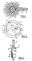
- La figure 4 est une vue mi-coupe longitudinale/mi-élévation à échelle agrandie, d'un clapet de seconde détente de l'ensemble de commande de la figure 1 ;
- La figure 5 est une vue en coupe longitudinale partielle à échelle agrandie d'une extrémité de l'ensemble de commande de la figure 1, montrant en position active un système d'indexation angulaire du dispositif de sélection de débit de gaz basse pression ;
- La figure 6 est une vue en coupe analogue à la figure 1 d'un ensemble incorporant une variante préférée de clapet de remplissage ; et,
- Les figures 7 et 8 sont des vues en coupe partielle montrant la séquence d'ouverture du clapet de remplissage de la figure 6.
- Figure 1 is a longitudinal sectional view of a gas control and distribution assembly according to the invention;
- Figure 2 is a cross-sectional view along 2/2 of Figure 1;
- Figure 3 is a schematic cross-sectional view along 3/3 of Figure 1;
- Figure 4 is a longitudinal half-section / mid-elevation view on an enlarged scale, of a second expansion valve of the control assembly of Figure 1;
- Figure 5 is a partial longitudinal sectional view on an enlarged scale of one end of the control assembly of Figure 1, showing in active position an angular indexing system of the low pressure gas flow selection device;
- Figure 6 is a sectional view similar to Figure 1 of an assembly incorporating a preferred variant of the filling valve; and,
- Figures 7 and 8 are partial sectional views showing the opening sequence of the filling valve of Figure 6.
L'ensemble de commande et distribution de gaz représenté aux dessins est adapté pour être raccordé à un réservoir (non représenté), ou plus particulièrement une bouteille contenant du gaz sous haute pression, notamment un gaz à usage médical, typiquement de l'oxygène.The gas control and distribution assembly shown in the drawings is adapted to be connected to a reservoir (not shown), or more particularly a bottle containing gas under high pressure, in particular a gas for medical use, typically oxygen.
Cet ensemble de commande comprend un corps allongé 1 dont une extrémité inférieure 2 est filetée pour pouvoir être vissée dans une ouverture taraudée correspondante de l'entrée du réservoir, et dans laquelle est ménagé un alésage longitudinal 3 d'entrée du gaz du réservoir. Dans le corps 1, sont disposés un clapet d'isolation 4 exposé au gaz sous haute pression parvenant par l'alésage 3, un détendeur de pression 5 disposé en aval du tiroir 4, et un raccord latéral 6 de sortie de gaz à moyenne pression.This control assembly comprises an
L'ensemble comprend également un second étage de détente 7 placé en aval du détendeur 5 et situé en regard d'un raccord 8 de sortie de gaz à pression réduite (c'est-à-dire à une pression supérieure à la pression atmosphérique), un dispositif 9 de sélection et de régulation du débit de gaz basse pression par le raccord 8, et un organe tubulaire 11 coiffant une partie supérieure tubulaire du corps 1 et de même axe longitudinal X-X que cette dernière, et contenant le clapet d'isolation 4, le détendeur 5, le second étage de détente 7 et le sélecteur de débit 9.The assembly also includes a
Les moyens de remplissage du réservoir 1 comprennent un clapet 12 monté dans un alésage étagé transversal du corps 1 entre l'extrémité filetée 2 et le tiroir 4, ce clapet étant sollicité en position de fermeture par un ressort 13 prenant appui sur un filtre poreux 14 pontant l'alésage 3.The means for filling the
Le clapet 12 débouche dans un embout latéral d'entrée 15 dans lequel est ménagé un taraudage 16 pour le vissage d'un raccord de connexion à un récipient de remplissage, cet embout présentant une collerette d'entrée 17 dont le diamètre est inférieur à celui du taraudage 16 et interdisant le vissage de tout raccord qui aurait les mêmes diamètres et pas que le taraudage 16, garantissant le remplissage du réservoir et l'adéquation de son contenu lors de son utilisation. En effet le remplissage ne peut s'effectuer que par un dispositif adapté, tel que celui décrit dans le document FR-A-2 726 346.The
L'organe tubulaire 11 de commande coiffe la partie supérieure du corps 1 et comporte à son extrémité inférieure en vis-à-vis du clapet d'isolation constitué par le tiroir 4, deux rampes ou surfaces opposées formant cames 18, 19, ménagées sur sa paroi intérieure. Les rampes 18, 19 sont en contact avec les extrémités opposées arrondies 4a, 4b faisant saillie hors du corps 1 du tiroir 4, lequel est disposé orthogonalement à l'axe longitudinal XX du corps 1 et de l'organe tubulaire 11.The
Les rampes 18, 19 (figure 3) se raccordent l'une à l'autre et s'étendent angulairement sur la plus grande partie de la circonférence intérieure de l'extrémité de l'organe tubulaire 11, leurs extrémités opposées A,D, étant séparées par une partie en saillie angulaire intérieure 21. Les extrémités opposées 4a, 4b du tiroir 4 sont arrondies de façon à faciliter leur glissement sur les rampes 18, 19, qui sont profilées de manière qu'une rotation de l'organe tubulaire 11 entraîne un déplacement en translation du tiroir 4 transversalement dans un sens ou dans le sens opposé suivant le sens de rotation de l'organe tubulaire 11, en ouvrant ou en fermant corrélativement le clapet d'isolation 4.The
Plus particulièrement, on voit à la figure 3 que les rampes 18, 19 sont diamétralement opposées et que tandis que le rayon de courbure de la rampe 18 décroît de son extrémité A à son extrémité B, le rayon de courbure de la rampe 19 croît de son extrémité C, diamétralement opposée à l'extrémité A, jusqu'à son extrémité D, diamétralement opposée à l'extrémité B de la rampe 18. Les extrémités adjacentes B et C des rampes sont raccordées par un secteur circulaire de rayon sensiblement constant. On comprend que dans ces conditions, la rotation de l'organe 11 provoque une translation transversale du tiroir 4 dans son logement 26 du corps 1 dans l'un des deux sens indiqués par les flèches F1, F2. Pour la commodité de la description on a représenté la seconde position 4.1 du tiroir 4 décalée angulairement de sa première position avec ses extrémités 4a, 4b en butée contre les extrémités de l'épaulement 21, au niveau des points B et D. Mais en réalité la position 4.1 est décalée uniquement en translation par rapport à la position 4 puisque c'est l'organe 11 qui tourne autour de son axe XX, et non le tiroir 4.More particularly, it can be seen in FIG. 3 that the
Comme on le voit sur la figure 1, le tiroir 4 comprend une partie centrale 23, portant un joint et coulissant de manière étanche dans un joint d'étanchéité 24 et dans une douille 25 montée dans un alésage étagé transversal du corps 1, et qui est suivie d'une section 22 de plus petit diamètre, située en regard du débouché de l'alésage d'entrée 3, elle-même raccordée à une collerette 27, portant un joint et de même diamètre que la partie centrale 23 et coulissant dans une portion de diamètre réduit 26 de l'alésage transversal où débouche l'alésage d'entrée 3. En regard, (en position de fermeture), de la partie centrale 23 du tiroir, la douille 25 forme une chambre intérieure 10 et est percée de trous radiaux 28 permettant le passage du gaz de la chambre 10 dans une chambre annulaire périphérique 29 et de là dans un alésage axial 31 du corps 1 débouchant dans une chambre axiale 32 qui elle-même communique avec une chambre supérieure 33 de plus grand diamètre, formées coaxialement dans la partie supérieure du corps 1. Les chambres 32 et 33 contiennent le détendeur amont 5 ainsi que la soupape d'évacuation 34 de gaz résiduel, qui sont agencés comme suit. Le détendeur 5 comprend une queue de piston cylindrique 35, dont une extrémité est engagée de manière coulissante dans la chambre inférieure 32 et présente un alésage transversal 36 débouchant dans la chambre 32, laquelle communique également avec le canal de sortie 37 du raccord 6. L'alésage 36 communique avec un canal longitudinal 38 de la queue centrale 35, débouchant à l'extrémité opposée de cette dernière, laquelle est prolongée par un piston 39 monté coulissant de manière étanche dans la chambre supérieure 33. Dans la queue centrale 35 est pratiqué un second alésage transversal 41 dont les extrémités opposées débouchent dans un espace intercalaire 42 délimité par le fond de la chambre 33 et une soupape 43 montée coaxiale sur la queue centrale 35. Un joint d'étanchéité 44 est interposé entre la face inférieure de la soupape 43 et le fond en regard de la chambre 33. La soupape 43 est sollicitée en appui sur le joint 44, contre le fond par un ressort hélicoïdal 45 coaxial à la soupape 43 et à la queue tubulaire 35 du détendeur 5. Le piston 39 coulisse de manière étanche dans la chambre 33 grâce à un joint d'étanchéité périphérique 46.As can be seen in FIG. 1, the drawer 4 comprises a
Le dispositif de soupape 34 d'évacuation de la pression résiduelle au niveau du détendeur 5 est complété par des perçages radiaux 47, 48 formés respectivement dans la paroi tubulaire 49 de la partie supérieure du corps 1 et dans la paroi de l'organe tubulaire 11.The valve device 34 for evacuating the residual pressure at the
L'ensemble de commande et de distribution comprend, en outre, en aval longitudinalement du détendeur 5 et en direction de l'extrémité supérieure de l'organe 11 opposée au tiroir 4, un second étage 7 de détente, situé au niveau de l'embout 8 basse pression, qui va maintenant être décrit.The control and distribution assembly further comprises, downstream longitudinally of the
Ce système 7 de seconde détente, ou détente aval, comporte un dispositif 51 à clapet de détente (figures 1 et 4) monté dans une saillie tubulaire axiale 52 d'un corps tubulaire 53 engagé à l'intérieur du corps 1 et sur une extrémité 54 duquel vient s'emboîter l'organe tubulaire 11. Ce corps 53 est fixe en rotation et en translation axiale, et contient une cloche 55 à l'intérieur de laquelle s'étend la saillie axiale 52. Un piston 56 est monté coulissant de manière étanche à l'intérieur de la chambre 57 de la cloche 55, un ressort hélicoïdal 58 étant disposé coaxialement à l'axe XX et exerçant une poussée axiale vers le bas sur le piston 56. Le ressort 58 prend appui sur une vis tubulaire 59 logée dans l'extrémité supérieure de la cloche 55 et qui permet le réglage de la compression du ressort 58 donc de sa poussée sur le piston 56. Ce réglage est exécuté de telle sorte que le ressort 58 exerce sur le piston 56 une poussée qui maintient le clapet 51 de seconde détente ouvert tant qu'aucun gaz ne parvient du détendeur 5.This system of second expansion, or downstream expansion, comprises a
L'extrémité inférieure de la cloche 55, opposée au ressort 58 forme une jupe tubulaire dans laquelle sont agencés, au niveau de l'alésage 61 du raccord transversal 8 de sortie basse pression, une série de trous radiaux 62...67, angulairement décalés les uns des autres, en nombre approprié et de diamètre croissant à partir du premier trou 62. Ces trous 62...67 permettent le passage du gaz ayant traversé le second clapet de détente 51 dans l'alésage 61 du raccord de sortie basse pression 8 vissé dans le corps tubulaire 53 (figure 2).The lower end of the
Le clapet de détente 51 comporte (figure 4) un corps tubulaire 80 formant, à son extrémité inférieure, un siège 90 sur lequel peut prendre appui de manière étanche un joint 100 fixé à une tige axiale 50 sollicitée vers le haut, en position de fermeture du clapet, par un ressort hélicoïdal 40. L'extrémité supérieure de la tige 50 porte en appui contre le piston de détente 56. Ce dernier maintient normalement sur la tige 50 une poussée légèrement supérieure à la poussée opposée du ressort 40, de sorte que le joint 100 est maintenu écarté du siège 90 et que le clapet 51 reste ouvert.The
La cloche 55 comporte une extrémité supérieure centrale 55a qui traverse un disque 70 logé dans un évidement de l'extrémité supérieure de l'organe tubulaire 11 et avec lequel elle est solidarisée de manière appropriée, par exemple par des plats longitudinaux 68. Sur la face extérieure du disque 70 et le long de sa périphérie sont prévus des repères numériques (non visibles au dessin) du débit de gaz basse pression sortant par le raccord 8, un bouton manuel 69 solidaire du disque 70 et de la cloche 55 permettant de sélectionner et d'afficher la valeur de débit choisie. A chaque positionnement de l'un des trous calibrés 62...67 (figure 2) en regard de l'alésage 61 de sortie basse pression, correspond un débit déterminé de gaz.The
A ce dispositif de sélection et de régulation du débit de gaz basse pression, est associé un système d'indexation comprenant un doigt longitudinal 71 pouvant coulisser dans un alésage 72 du corps tubulaire 53 fixe, concentrique à la cloche 55 (figures 5 et 6) en traversant une lumière continue 73 de l'organe tubulaire 11 de commande. Le doigt 71 constitue un index sollicité élastiquement par un ressort 74 dans sa position de sortie, dans laquelle son extrémité est engagée dans l'une 75 d'une série d'empreintes ménagées sur la périphérie de la face interne du disque rotatif 70. Le doigt ou index 71 et les empreintes 75, lesquelles sont en nombre égal au nombre de trous 62...67, sont positionnés de telle sorte que le doigt 71 soit engagé dans une empreinte 75 à chaque fois qu'un trou calibré 62...67 est placé en regard de l'orifice de l'embout de sortie 61. A la figure 5, l'index 71 est ainsi engagé dans une empreinte 75. Quand on fait tourner le disque 70, l'index 71 se rétracte tant que l'on n'est pas parvenu à l'empreinte 75 suivante.With this device for selecting and regulating the low pressure gas flow, is associated an indexing system comprising a
L'ensemble de commande et de distribution est également pourvu de moyens pour interdire la sélection d'un débit de gaz basse pression par l'embout 8 tant que le clapet d'isolation 4 est fermé, et inversement pour interdire la fermeture du clapet 4 tant que les moyens de sélection 9 du débit sont ouverts. Dans le mode de réalisation représenté, ces moyens comprennent une première encoche 76 agencée dans la paroi extérieure de la cloche 55, et une seconde encoche 77 formée dans la paroi intérieure de l'extrémité de l'organe de commande tubulaire 11. Ces deux encoches 76, 77 sont agencées au même niveau et en regard d'une lumière 78 formée dans le corps 53. Une bille 79 est logée dans la lumière 78 et dimensionnée de façon qu'elle soit engagée partiellement, soit dans l'encoche 76 soit dans l'encoche 77, en fonction des positions angulaires respectives de la cloche 55 et de l'organe tubulaire 11, alors que le corps 53 est fixe. En effet, les encoches 76 et 77 peuvent être décalées angulairement d'un angle approprié de manière à pouvoir, ou non, se trouver l'une en face de l'autre. De ce fait, lorsque la bille 78 est engagée dans l'encoche 76 comme représenté à la figure 1, elle interdit de faire tourner la cloche 55 au moyen du bouton 69 donc de sélectionner un débit de sortie basse pression, alors qu'au contraire il est possible de faire tourner l'organe tubulaire 11 pour commander le clapet d'isolation 4. Par ailleurs, pour une position angulaire appropriée de l'organe 11, l'encoche 77 parvient en regard de la bille 78. Il devient alors possible de faire tourner la cloche 55 par le bouton 69, de manière à chasser la bille 78 pour qu'elle s'engage partiellement dans l'encoche 77. A partir de ce moment l'organe tubulaire 11 est bloqué en rotation, donc le tiroir d'isolation 4 ne peut plus être actionné, tandis qu'au contraire les moyens de sélection 9 du débit de sortie basse pression peuvent être actionnés, puisque la bille 78 n'est plus engagée dans l'encoche 76 et ne s'oppose donc plus à la rotation de la cloche 55.The control and distribution assembly is also provided with means to prohibit the selection of a low pressure gas flow rate through the
On comprend donc que cet agencement fournit une sécurité renforcée à l'utilisation de l'ensemble de commande et de distribution.It is therefore understood that this arrangement provides increased security in the use of the control and distribution assembly.
Le fonctionnement de cet ensemble est le suivant. Le gaz provenant du réservoir entre dans l'alésage 3 comme indiqué par la flèche (figure 1), tandis que le clapet 12 est évidemment en position de fermeture de l'embout 15. Le gaz parvient dans le logement annulaire 26, entre le segment central 23 et la collerette 27. Sur la figure 1, le tiroir 4 est représenté en position de fermeture, de sorte que le gaz haute pression ne peut parvenir dans le volume annulaire 10 réservé entre la partie centrale 23 et la douille 25.The operation of this assembly is as follows. The gas coming from the reservoir enters the
Lorsqu'on fait tourner l'organe de commande 11 dans le sens approprié, compte tenu de l'orientation des rampes de guidage 18, 19, on provoque un déplacement du tiroir 4 en translation dans la direction qui l'entraîne vers la gauche sur la figure 1. Sa partie centrale 23 parvient alors dans une position (non représentée) où elle libère un passage pour le gaz du logement 26 dans la chambre annulaire 10, d'où, au travers des trous 28, il pénètre dans l'alésage 31, la chambre 32, les alésages 36, 38, 41, la chambre 42. En fonction de la force appliquée par le gaz comprimé sur la soupape 34, qui est proportionnelle à la section de celle-ci et au diamètre du joint 43, la soupape 34 peut se décoller et libérer une partie du gaz pour l'évacuer à l'extérieur par les orifices 47 et 48.When the
Le gaz à moyenne pression dans la chambre 32 peut être directement évacué par l'embout de sortie moyenne pression 6. Le gaz moyenne pression peut aussi franchir le détendeur 5, parvenir en regard du clapet de seconde détente 51, qu'il franchit pour remplir la chambre 57. La légère augmentation de pression dans celle-ci exerce alors sur le piston 56 une poussée qui ferme le clapet 51, et de là le gaz à basse pression (légèrement supérieure à la pression atmosphérique) est évacué par le raccord de sortie basse pression 8 à un débit réglé par le choix de l'un des trous 62...67, positionné en regard de l'alésage de sortie 61 par la rotation de la cloche 55 au moyen du bouton manuel 69. Dès que la pression a baissé dans la chambre 57, le piston 56 ouvre à nouveau le clapet 51, et ainsi de suite. L'opérateur lit sur la face extérieure du disque 70 le repère sélectionné correspondant au débit de sortie choisi.The medium-pressure gas in the chamber 32 can be directly evacuated by the medium-
A chaque valeur sélectionnée du débit de sortie, correspond l'indexation du doigt 71 dans l'une des encoches 75. Pendant l'opération de sélection du débit, l'organe tubulaire 11 ne peut être actionné en rotation en raison du système de sécurité constitué par la bille 78 et les encoches 76, 77, comme décrit précédemment.Each selected value of the output flow corresponds to the indexing of the
Grâce au fait que les trous 62...67 (qui évidemment peuvent être en nombre variable) sont ménagés de façon à faire face à la sortie basse pression 8, ces trous peuvent être réalisés par un foret mécanique, donc de manière beaucoup moins onéreuse que les trous du brevet européen précité, qui doivent être obtenus par un moyen chimique. En effet, les trous 62...67 peuvent être réalisés avec une tolérance de l'ordre du 1/100 mm alors qu'elle était de l'ordre du micron pour les trous du dispositif antérieur, de sorte que l'on maîtrise mieux ces perçages, ainsi que les tolérances d'usinage et de débit.Thanks to the fact that the
Par ailleurs la pression à l'intérieur du réservoir de gaz peut s'étendre de 200x105 Pa à 10x105 Pa. A la sortie du premier détendeur 5, la pression gazeuse peut varier de quelques centaines de millibars, et à celle du deuxième détendeur 7, cette variation de pression peut être ramenée à quelques dizaines de millibars environ. On obtient ainsi une maîtrise totale du débit, grâce à l'agencement d'un second détendeur 7 qui permet l'obtention d'une pression de sortie pratiquement constante, quel que soit le débit prélevé. Comme déjà indiqué, la réunion en un seul dispositif du détendeur 5 et de la soupape 34 d'évacuation de la pression résiduelle de gaz contribue à simplifier notablement la réalisation de l'ensemble de distribution, et donc à diminuer son coût de fabrication.Furthermore, the pressure inside the gas tank can range from 200 × 10 5 Pa to 10 × 10 5 Pa. At the outlet of the
Comme susmentionné, le remplissage d'un réservoir équipé d'un ensemble de commande et de distribution selon l'invention s'effectue par les moyens de remplissage comprenant essentiellement l'élément de clapet 12 monté mobile axialement dans un alésage étagé 120 formé transversalement dans la partie inférieure du corps 1, interceptant le passage d'entrée 3 et traversant le corps pour permettre le montage, sur son extrémité opposée au clapet 12, d'un manomètre haute pression 81.As mentioned above, the filling of a tank equipped with a control and distribution assembly according to the invention is carried out by the filling means essentially comprising the
Comme on le voit mieux sur les figures 6 à 8, l'alésage étagé 120 comprend avantageusement une partie intérieure cylindrique droite se raccordant, vers l'entrée, via un premier épaulement radial 121, avec une première partie de diamètre réduit 122, laquelle se raccorde, via un second épaulement radial 123, avec une seconde partie de diamètre réduit formant col 124, qui s'évase ensuite largement pour se raccorder au taraudage 16 de l'embout de raccordement 15 servant au montage de l'équipement de remplissage déplaçant mécaniquement l'élément de clapet 12 vers sa position d'ouverture.As best seen in Figures 6 to 8, the stepped bore 120 advantageously comprises a straight cylindrical inner part connecting, towards the inlet, via a first
Comme on le voit mieux sur les figures 7 et 8, l'élément de clapet 12 comporte une partie de corps principale arrière de diamètre correspondant sensiblement au diamètre de la première partie de diamètre réduit 122 et dans laquelle est formée une gorge annulaire 124 recevant le joint annulaire d'étanchéité 125 coopérant normalement, en position de fermeture du clapet, avec la paroi de la portion de diamètre réduit 122 de l'alésage 120. La partie principale du corps de l'élément de clapet se prolonge vers l'avant, au delà d'un épaulement radial 126, par une partie intermédiaire de diamètre réduit 127, de diamètre correspondant sensiblement à celui du col 124, et elle-même prolongée par une queue d'extrémité avant 128 faisant saillie hors du col 124 pour coopérer avec l'équipement de remplissage lors de la mise en place de ce dernier dans l'alésage 16.As best seen in Figures 7 and 8, the
Selon un aspect de l'invention, le moyen de clapet de remplissage comporte en outre une cage métallique 130 montée à coulissement dans la partie principale de l'alésage étagé 120 et comportant, extérieurement, des passages axiaux 131. La cage 130 comporte une chambre intérieure ouverte vers l'avant et latéralement délimitée par un alésage 132 ayant le même diamètre que la première portion de diamètre réduit 122, et partiellement, vers l'arrière, par un épaulement radial 133. La cage 130 est sollicitée axialement en butée par son extrémité avant contre l'épaulement 121, par le ressort 13 disposé dans l'alésage étagé 120 et prenant appui sur un filtre 14 disposé à l'intersection de l'alésage 120 et du passage 3 et s'étendant en travers de ce dernier.According to one aspect of the invention, the filling valve means further comprises a
Le fonctionnement du clapet de remplissage selon l'invention est le suivant :The operation of the filling valve according to the invention is as follows:
Dans la position de fermeture représentée sur la figure 1, l'élément de clapet 12 est plaqué, par la pression résiduelle dans le réservoir, avec son épaulement avant 126 en butée contre l'épaulement 123 de l'alésage étagé et avec le joint 125 coopérant en étanchéité avec la paroi de la première portion de diamètre réduit 122 de l'alésage étagé. La cage 130 est plaquée, par le ressort 13, contre l'épaulement 121, avec l'épaulement central 133 à distance de la face arrière de l'élément de clapet 12.In the closed position shown in Figure 1, the
Lors de la mise en place, dans le taraudage 16, de l'équipement de remplissage, ce dernier, venant porter contre la queue 128, repousse l'élément de clapet 12 vers l'amère de l'alésage étagé (vers la droite sur les figures 1 à 3).During the fitting, in the
Dans un premier temps, représenté sur la figure 2, l'élément de clapet 12 est reculé d'une distance telle que le joint 125 quitte la portion de diamètre réduit 122 de l'alésage étagé pour être reçu dans l'alésage 132 de la cage 130, la face arrière de l'élément de clapet 12 étant toujours écartée de l'épaulement 133.Firstly, represented in FIG. 2, the
Par la suite, l'élément de clapet 12 continuant à être repoussé vers l'intérieur, la face d'extrémité arrière de l'élément de clapet 12 vient porter contre l'épaulement interne 133 de la cage 130, tout complément de déplacement de l'élément de clapet 12 s'effectuant dès lors en entraînant la cage 130 à l'encontre du ressort 13, en libérant complètement le passage de gaz de l'extérieur vers l'intérieur de l'alésage étagé puis, via le filtre 14, et le passage d'entrée 3, dans le réservoir.Thereafter, the
On comprendra que, dès la configuration de la figure 2, le joint 125 vient se loger dans la cage 130, le joint demeurant à l'abri de cette dernière dès la pleine ouverture de l'accès à l'alésage étagé et pendant toute la séquence de remplissage, la cage 130 assurant ainsi, comme susmentionné, un rôle d'écran protecteur à la fois mécanique et thermique.It will be understood that, from the configuration of FIG. 2, the
Claims (14)
Applications Claiming Priority (2)
| Application Number | Priority Date | Filing Date | Title |
|---|---|---|---|
| FR9606925A FR2749641B1 (en) | 1996-06-05 | 1996-06-05 | GAS CONTROL AND DISTRIBUTION ASSEMBLY FOR HIGH PRESSURE GAS TANK |
| FR9606925 | 1996-06-05 |
Publications (2)
| Publication Number | Publication Date |
|---|---|
| EP0811900A1 true EP0811900A1 (en) | 1997-12-10 |
| EP0811900B1 EP0811900B1 (en) | 2001-05-09 |
Family
ID=9492735
Family Applications (1)
| Application Number | Title | Priority Date | Filing Date |
|---|---|---|---|
| EP97401216A Expired - Lifetime EP0811900B1 (en) | 1996-06-05 | 1997-06-02 | Gas control and dispensing assembly for gas cylinder |
Country Status (9)
| Country | Link |
|---|---|
| US (1) | US5996625A (en) |
| EP (1) | EP0811900B1 (en) |
| JP (1) | JPH1096500A (en) |
| CN (1) | CN1069394C (en) |
| AT (1) | ATE201102T1 (en) |
| CA (1) | CA2206821C (en) |
| DE (1) | DE69704745T2 (en) |
| ES (1) | ES2158464T3 (en) |
| FR (1) | FR2749641B1 (en) |
Cited By (4)
| Publication number | Priority date | Publication date | Assignee | Title |
|---|---|---|---|---|
| EP1462140A1 (en) | 2003-03-26 | 2004-09-29 | Taema | First aid portable ventilator |
| CN103016952A (en) * | 2012-12-29 | 2013-04-03 | 天台县铭通机械有限公司 | Automatic gas source distributor with safety function |
| FR3024204A1 (en) * | 2014-07-28 | 2016-01-29 | Cahouet | VALVE CLOSING DEVICE BY OPERATING THE RELIEF VALVE |
| EP2799187A3 (en) * | 2013-04-29 | 2016-05-04 | Basso Industry Corp. | Metering valve |
Families Citing this family (53)
| Publication number | Priority date | Publication date | Assignee | Title |
|---|---|---|---|---|
| DE19810286A1 (en) * | 1998-03-10 | 1999-09-23 | Siemens Ag | Micro-sensor |
| US6647982B1 (en) * | 1998-06-29 | 2003-11-18 | Zaiser Lenoir E. | Gas flow device |
| DE19950352C2 (en) * | 1999-10-19 | 2002-03-07 | Hilti Ag | Portable, combustion powered tool and method for driving its piston |
| EP1126202B1 (en) * | 2000-02-18 | 2004-09-22 | Kabushiki Kaisha Neriki | Valve assembly for gas cylinder |
| US6766829B2 (en) | 2000-02-18 | 2004-07-27 | Kabushiki Kaisha Neriki | Valve assembly for gas cylinder |
| US6478046B2 (en) * | 2001-01-20 | 2002-11-12 | Stanely Gabrel | Gas pressure regulator |
| US6595230B2 (en) | 2001-08-08 | 2003-07-22 | Western Industries, Inc. | Non-refillable valve for a gas cylinder |
| JP3796150B2 (en) * | 2001-09-18 | 2006-07-12 | Smc株式会社 | Simple maintenance 2 port valve |
| US7225810B2 (en) * | 2002-01-11 | 2007-06-05 | Hamai Industries Limited | Valve for use in high pressure gas containers |
| US7007714B2 (en) * | 2003-12-05 | 2006-03-07 | Hose Shop, Ltd. | High pressure traverse flow adjustable gas regulator |
| ATE392577T1 (en) * | 2004-07-21 | 2008-05-15 | African Oxygen Ltd | MULTIFUNCTIONAL VALVE UNIT |
| CN100565011C (en) * | 2004-09-14 | 2009-12-02 | 株式会社东海 | The connector construction of with locking mechanism |
| US20060060251A1 (en) * | 2004-09-23 | 2006-03-23 | Gamard Stephan C F | Gas cylinder dispensing valve |
| US7237570B2 (en) * | 2004-09-23 | 2007-07-03 | Praxair Technology, Inc. | Gas cylinder dispensing valve |
| US20060225795A1 (en) * | 2005-03-30 | 2006-10-12 | Baker George D | Push button regulator device with sealing element to facilitate easy connection with other devices |
| US7757681B2 (en) * | 2005-05-06 | 2010-07-20 | Tippmann Sports Llc | Safety paintball gun regulator |
| FR2892799B1 (en) * | 2005-10-27 | 2007-12-28 | Air Liquide | FLUID FILLING AND / OR SUPPLY CONTROL DEVICE AND TANK COMPRISING SUCH A DEVICE |
| US7481241B2 (en) * | 2006-05-08 | 2009-01-27 | Dale Carpenter | Method and apparatus for a pressure regulator |
| EP1953429A1 (en) * | 2007-02-01 | 2008-08-06 | Luxembourg Patent Company S.A. | Gas valve assembly with integrated pressure reducer |
| JP4614978B2 (en) | 2007-02-08 | 2011-01-19 | トヨタ自動車株式会社 | Sealing material for high-pressure hydrogen container and high-pressure hydrogen container |
| FR2914385B1 (en) * | 2007-03-29 | 2009-07-03 | Taema | TAP FOR GAS BOTTLE UNDER PRESSURE |
| US20100276614A1 (en) * | 2007-09-14 | 2010-11-04 | Daryll Duane Patterson | Modular in-line fluid regulators |
| US20090114294A1 (en) * | 2007-10-25 | 2009-05-07 | Rubicon Manufacturing, Inc. | Portable gas shock or air bag inflator or deflator |
| FR2924198B1 (en) * | 2007-11-22 | 2010-05-28 | Air Liquide Electronics Systems | MINIATURE GAS CABINET |
| LU91384B1 (en) * | 2007-12-12 | 2009-06-15 | Luxembourg Patent Co | Arrangement of a filling and filtration device in a valve body |
| CA2711161C (en) * | 2008-01-14 | 2014-10-07 | Pi-Design Ag | Double-walled vessel having pressure compensation opening |
| US8336577B2 (en) | 2008-04-23 | 2012-12-25 | Praxair Technology, Inc. | Pressurized gas containing system |
| US20100031943A1 (en) * | 2008-08-08 | 2010-02-11 | K&L Air Products Inc. | Coupler Assembly for Dispensing Fluid from a Compressed Fluid Source |
| US20100212757A1 (en) * | 2009-02-26 | 2010-08-26 | Daryll Duane Patterson | In-line pressure regulators |
| BRPI1013879B1 (en) * | 2009-03-11 | 2020-07-21 | Victor Equipment Company | gas pressure regulator having overlapping indicators |
| LU91582B1 (en) * | 2009-06-30 | 2010-12-31 | Luxembourg Patent Co | Regulator with shutter and flow selector. |
| US8498418B2 (en) * | 2009-08-31 | 2013-07-30 | International Business Machines Corporation | Conversion of cryptographic key protection |
| US8011380B2 (en) * | 2009-10-01 | 2011-09-06 | Vision Tech International Llp | Single component two-stage regulator |
| US8517043B2 (en) * | 2009-11-10 | 2013-08-27 | Pentair Valves & Controls US LP | Pressure build economizer valve |
| WO2012030699A2 (en) * | 2010-09-01 | 2012-03-08 | Ysn Imports, Inc. | Gas pressure regulator system |
| AU2012327240A1 (en) * | 2011-11-23 | 2013-06-06 | Micro Matic A/S | A pressure delivery system |
| US9103501B1 (en) * | 2013-07-10 | 2015-08-11 | Cai YANG | Gas cylinder safety purge and anchor system |
| US20150013776A1 (en) * | 2013-07-15 | 2015-01-15 | Cyltex, Limited Liability Company | Regulating Valve |
| LU92395B1 (en) * | 2014-03-07 | 2015-09-08 | Luxembourg Patent Co Sa | Pressure reducer with flow selector for gas cylinder |
| FR3025585B1 (en) * | 2014-09-09 | 2016-09-09 | Air Liquide Medical Systems | BLOCK TAP FOR GAS CONTAINER WITH IMPROVED USE SAFETY |
| CN105485395A (en) * | 2015-11-25 | 2016-04-13 | 宁波瑾科机械制造有限公司 | Valve body of medical oxygen cylinder valve |
| US10564656B2 (en) * | 2016-12-13 | 2020-02-18 | Praxair Technology, Inc. | Gas delivery valve and methods of use thereof |
| FR3067094B1 (en) * | 2017-06-01 | 2020-08-14 | L'air Liquide Sa Pour L'etude Et L'exploitation Des Procedes Georges Claude | TAP, STORAGE AND FILLING STATION |
| DE102018000890A1 (en) * | 2018-02-03 | 2019-08-08 | Messer Industriegase Gmbh | Gas sampling valve for a compressed gas cylinder |
| LU100807B1 (en) * | 2018-05-30 | 2019-12-02 | Luxembourg Patent Co | Gas flow device with gas flow selector mounted by insertion |
| LU100957B1 (en) * | 2018-10-11 | 2020-04-14 | Luxembourg Patent Co | Gas pressure reducer with cam commanded shut-off valve |
| LU100958B1 (en) * | 2018-10-11 | 2020-04-14 | Luxembourg Patent Co | Gas pressure reducer with integrated shut-off valve |
| CN113195963B (en) * | 2018-10-18 | 2023-09-12 | 阿尔克里斯流体控制服务公司 | Device for filling and extracting gas |
| US11085586B2 (en) | 2018-10-22 | 2021-08-10 | Pressure Specialist, Inc. | Regulated fill station |
| US11085585B2 (en) * | 2018-10-30 | 2021-08-10 | Pressure Specialist, Inc. | Fill station |
| CN113090941B (en) * | 2021-04-26 | 2022-09-20 | 中国人民解放军海军工程大学 | Quick-inflating steel cylinder valve suitable for high-pressure gas cylinder |
| US11372431B1 (en) * | 2021-05-10 | 2022-06-28 | Bayotech, Inc. | Multi-function three-stage pressure regulator |
| US11732843B2 (en) * | 2021-07-19 | 2023-08-22 | Caterpillar Inc. | On-tank regulator for high-pressure tank |
Citations (2)
| Publication number | Priority date | Publication date | Assignee | Title |
|---|---|---|---|---|
| EP0417882A2 (en) * | 1989-09-14 | 1991-03-20 | Intel Gasgards Private Limited | Improvements in and relating to gas pressure regulators |
| EP0629937A1 (en) * | 1993-06-03 | 1994-12-21 | Taema | Control unit for gas distribution and bottle provided with such unit |
Family Cites Families (7)
| Publication number | Priority date | Publication date | Assignee | Title |
|---|---|---|---|---|
| DE97742C (en) * | ||||
| US2972466A (en) * | 1957-08-09 | 1961-02-21 | Fyr Fyter Co | Discharge head |
| GB1174314A (en) * | 1967-05-25 | 1969-12-17 | Distillers Co Carbon Dioxide | A Dispensing Device for Gases Under Pressure. |
| US4173986A (en) * | 1977-04-18 | 1979-11-13 | American Safety Equipment Corporation | Pressurized gas flow control valve and assembly thereof with reducer regulator |
| US4655246A (en) * | 1983-09-30 | 1987-04-07 | Essex Industries, Inc. | Regulated gas flow control valve |
| US4898210A (en) * | 1988-01-12 | 1990-02-06 | Kabushiki Kaisha Neriki | Gas-cylinder valve |
| US5665894A (en) * | 1996-03-01 | 1997-09-09 | Air Liquide America Corporation | Instrument calibrating demand flow regulator |
-
1996
- 1996-06-05 FR FR9606925A patent/FR2749641B1/en not_active Expired - Fee Related
-
1997
- 1997-05-28 US US08/864,351 patent/US5996625A/en not_active Expired - Fee Related
- 1997-06-02 ES ES97401216T patent/ES2158464T3/en not_active Expired - Lifetime
- 1997-06-02 DE DE69704745T patent/DE69704745T2/en not_active Expired - Lifetime
- 1997-06-02 AT AT97401216T patent/ATE201102T1/en not_active IP Right Cessation
- 1997-06-02 EP EP97401216A patent/EP0811900B1/en not_active Expired - Lifetime
- 1997-06-03 CA CA002206821A patent/CA2206821C/en not_active Expired - Fee Related
- 1997-06-04 CN CN97112924A patent/CN1069394C/en not_active Expired - Fee Related
- 1997-06-04 JP JP9146355A patent/JPH1096500A/en active Pending
Patent Citations (2)
| Publication number | Priority date | Publication date | Assignee | Title |
|---|---|---|---|---|
| EP0417882A2 (en) * | 1989-09-14 | 1991-03-20 | Intel Gasgards Private Limited | Improvements in and relating to gas pressure regulators |
| EP0629937A1 (en) * | 1993-06-03 | 1994-12-21 | Taema | Control unit for gas distribution and bottle provided with such unit |
Cited By (5)
| Publication number | Priority date | Publication date | Assignee | Title |
|---|---|---|---|---|
| EP1462140A1 (en) | 2003-03-26 | 2004-09-29 | Taema | First aid portable ventilator |
| CN103016952A (en) * | 2012-12-29 | 2013-04-03 | 天台县铭通机械有限公司 | Automatic gas source distributor with safety function |
| EP2799187A3 (en) * | 2013-04-29 | 2016-05-04 | Basso Industry Corp. | Metering valve |
| FR3024204A1 (en) * | 2014-07-28 | 2016-01-29 | Cahouet | VALVE CLOSING DEVICE BY OPERATING THE RELIEF VALVE |
| EP3002499A1 (en) * | 2014-07-28 | 2016-04-06 | Cahouet | Valve closure device by actuating the expansion valve |
Also Published As
| Publication number | Publication date |
|---|---|
| CA2206821A1 (en) | 1997-12-05 |
| US5996625A (en) | 1999-12-07 |
| DE69704745D1 (en) | 2001-06-13 |
| JPH1096500A (en) | 1998-04-14 |
| CN1176361A (en) | 1998-03-18 |
| CA2206821C (en) | 2004-09-14 |
| DE69704745T2 (en) | 2002-02-28 |
| ATE201102T1 (en) | 2001-05-15 |
| CN1069394C (en) | 2001-08-08 |
| EP0811900B1 (en) | 2001-05-09 |
| FR2749641B1 (en) | 1998-08-21 |
| FR2749641A1 (en) | 1997-12-12 |
| ES2158464T3 (en) | 2001-09-01 |
Similar Documents
| Publication | Publication Date | Title |
|---|---|---|
| EP0811900B1 (en) | Gas control and dispensing assembly for gas cylinder | |
| EP2870516B1 (en) | Pressure-reducing valve having a residual pressure function built into the valve | |
| EP0485244B1 (en) | Dispensing valve for a container with a fluid under pressure of a gas, and container equipped with such a valve | |
| FR2706051A1 (en) | Gas distribution control assembly and gas cylinder equipped with such an assembly. | |
| LU88377A1 (en) | Bi-directional valve for a valve of a cylinder of compressed or liquefied gas and valve provided with such a valve | |
| EP2964933A1 (en) | Compact dosing device for an injector with two fuel circuits for an aircraft turbomachine | |
| EP1327804B1 (en) | Valve for pressure bottle | |
| EP0214023B1 (en) | Flow limitation device for a tap of a bottle containing gas liquefied or compressed under pressure | |
| EP3002499B1 (en) | Valve closure device by actuating the expansion valve | |
| FR2652426A1 (en) | GAS BOTTLE REGULATOR. | |
| FR2731071A1 (en) | DIFFERENTIAL PRESSURE INDICATOR | |
| EP3308235B1 (en) | Compact and pressure-balanced fluid regulator | |
| WO2011000839A1 (en) | Expansion valve with a plug and a flow selector | |
| EP0070778B1 (en) | Pilot device of a safety valve | |
| EP2780624B1 (en) | Gas bottle valve provided with a flywheel controlling a residual-pressure valve and a stop valve | |
| EP0526298B1 (en) | Actuator button for a pressurized container for spraying a liquid, and container provided with such an actuator button | |
| EP1861758B1 (en) | Overpressure protection device and connection subassembly comprising same | |
| FR2854877A1 (en) | Dosing valve for fluid product has dosing chamber at atmospheric pressure when valve is at rest, ensuring accurate dosing every time | |
| FR2503319A1 (en) | Safety valve for water heater - has free internal function pressure release even if exterior handle is blocked | |
| EP2572126B1 (en) | Cylinder valve having a residual pressure valve | |
| EP0428901B1 (en) | Pressure reducer which can be neutralised | |
| FR2618868A1 (en) | Device forming a pressure-relief element for automatically regulating the pressure of a gaseous fluid | |
| FR2563312A1 (en) | PRESSURE REDUCTION VALVE | |
| EP1634002B1 (en) | Filler and drain valve and cleaning tools for a pressure-fluid cylinder | |
| EP4257868A1 (en) | Improved valve for gas container with integrated expansion valve |
Legal Events
| Date | Code | Title | Description |
|---|---|---|---|
| PUAI | Public reference made under article 153(3) epc to a published international application that has entered the european phase |
Free format text: ORIGINAL CODE: 0009012 |
|
| AK | Designated contracting states |
Kind code of ref document: A1 Designated state(s): AT BE DE DK ES FR GB GR IT LU NL PT SE |
|
| 17P | Request for examination filed |
Effective date: 19980610 |
|
| AKX | Designation fees paid |
Free format text: AT BE DE DK ES FR GB GR IT LU NL PT SE |
|
| RBV | Designated contracting states (corrected) |
Designated state(s): AT BE DE DK ES FR GB GR IT LU NL PT SE |
|
| GRAG | Despatch of communication of intention to grant |
Free format text: ORIGINAL CODE: EPIDOS AGRA |
|
| GRAG | Despatch of communication of intention to grant |
Free format text: ORIGINAL CODE: EPIDOS AGRA |
|
| GRAH | Despatch of communication of intention to grant a patent |
Free format text: ORIGINAL CODE: EPIDOS IGRA |
|
| 17Q | First examination report despatched |
Effective date: 20000928 |
|
| GRAH | Despatch of communication of intention to grant a patent |
Free format text: ORIGINAL CODE: EPIDOS IGRA |
|
| GRAA | (expected) grant |
Free format text: ORIGINAL CODE: 0009210 |
|
| AK | Designated contracting states |
Kind code of ref document: B1 Designated state(s): AT BE DE DK ES FR GB GR IT LU NL PT SE |
|
| PG25 | Lapsed in a contracting state [announced via postgrant information from national office to epo] |
Ref country code: NL Free format text: LAPSE BECAUSE OF FAILURE TO SUBMIT A TRANSLATION OF THE DESCRIPTION OR TO PAY THE FEE WITHIN THE PRESCRIBED TIME-LIMIT Effective date: 20010509 |
|
| REF | Corresponds to: |
Ref document number: 201102 Country of ref document: AT Date of ref document: 20010515 Kind code of ref document: T |
|
| PGFP | Annual fee paid to national office [announced via postgrant information from national office to epo] |
Ref country code: AT Payment date: 20010608 Year of fee payment: 5 |
|
| REF | Corresponds to: |
Ref document number: 69704745 Country of ref document: DE Date of ref document: 20010613 |
|
| PGFP | Annual fee paid to national office [announced via postgrant information from national office to epo] |
Ref country code: GB Payment date: 20010615 Year of fee payment: 5 |
|
| ITF | It: translation for a ep patent filed |
Owner name: JACOBACCI & PERANI S.P.A. |
|
| PG25 | Lapsed in a contracting state [announced via postgrant information from national office to epo] |
Ref country code: PT Free format text: LAPSE BECAUSE OF FAILURE TO SUBMIT A TRANSLATION OF THE DESCRIPTION OR TO PAY THE FEE WITHIN THE PRESCRIBED TIME-LIMIT Effective date: 20010809 Ref country code: DK Free format text: LAPSE BECAUSE OF FAILURE TO SUBMIT A TRANSLATION OF THE DESCRIPTION OR TO PAY THE FEE WITHIN THE PRESCRIBED TIME-LIMIT Effective date: 20010809 |
|
| PG25 | Lapsed in a contracting state [announced via postgrant information from national office to epo] |
Ref country code: GR Free format text: LAPSE BECAUSE OF FAILURE TO SUBMIT A TRANSLATION OF THE DESCRIPTION OR TO PAY THE FEE WITHIN THE PRESCRIBED TIME-LIMIT Effective date: 20010810 |
|
| GBT | Gb: translation of ep patent filed (gb section 77(6)(a)/1977) |
Effective date: 20010806 |
|
| REG | Reference to a national code |
Ref country code: ES Ref legal event code: FG2A Ref document number: 2158464 Country of ref document: ES Kind code of ref document: T3 |
|
| NLV1 | Nl: lapsed or annulled due to failure to fulfill the requirements of art. 29p and 29m of the patents act | ||
| REG | Reference to a national code |
Ref country code: GB Ref legal event code: IF02 |
|
| PLBE | No opposition filed within time limit |
Free format text: ORIGINAL CODE: 0009261 |
|
| STAA | Information on the status of an ep patent application or granted ep patent |
Free format text: STATUS: NO OPPOSITION FILED WITHIN TIME LIMIT |
|
| 26N | No opposition filed | ||
| PG25 | Lapsed in a contracting state [announced via postgrant information from national office to epo] |
Ref country code: GB Free format text: LAPSE BECAUSE OF NON-PAYMENT OF DUE FEES Effective date: 20020602 Ref country code: AT Free format text: LAPSE BECAUSE OF NON-PAYMENT OF DUE FEES Effective date: 20020602 |
|
| GBPC | Gb: european patent ceased through non-payment of renewal fee |
Effective date: 20020602 |
|
| REG | Reference to a national code |
Ref country code: FR Ref legal event code: CD |
|
| PGFP | Annual fee paid to national office [announced via postgrant information from national office to epo] |
Ref country code: LU Payment date: 20150624 Year of fee payment: 19 Ref country code: ES Payment date: 20150619 Year of fee payment: 19 Ref country code: DE Payment date: 20150619 Year of fee payment: 19 Ref country code: SE Payment date: 20150618 Year of fee payment: 19 |
|
| PGFP | Annual fee paid to national office [announced via postgrant information from national office to epo] |
Ref country code: IT Payment date: 20150623 Year of fee payment: 19 Ref country code: BE Payment date: 20150618 Year of fee payment: 19 |
|
| REG | Reference to a national code |
Ref country code: FR Ref legal event code: PLFP Year of fee payment: 20 |
|
| PGFP | Annual fee paid to national office [announced via postgrant information from national office to epo] |
Ref country code: FR Payment date: 20160627 Year of fee payment: 20 |
|
| PG25 | Lapsed in a contracting state [announced via postgrant information from national office to epo] |
Ref country code: BE Free format text: LAPSE BECAUSE OF NON-PAYMENT OF DUE FEES Effective date: 20160630 |
|
| REG | Reference to a national code |
Ref country code: DE Ref legal event code: R119 Ref document number: 69704745 Country of ref document: DE |
|
| REG | Reference to a national code |
Ref country code: SE Ref legal event code: EUG |
|
| PG25 | Lapsed in a contracting state [announced via postgrant information from national office to epo] |
Ref country code: SE Free format text: LAPSE BECAUSE OF NON-PAYMENT OF DUE FEES Effective date: 20160603 |
|
| PG25 | Lapsed in a contracting state [announced via postgrant information from national office to epo] |
Ref country code: DE Free format text: LAPSE BECAUSE OF NON-PAYMENT OF DUE FEES Effective date: 20170103 |
|
| PG25 | Lapsed in a contracting state [announced via postgrant information from national office to epo] |
Ref country code: IT Free format text: LAPSE BECAUSE OF NON-PAYMENT OF DUE FEES Effective date: 20160602 |
|
| REG | Reference to a national code |
Ref country code: ES Ref legal event code: FD2A Effective date: 20180507 |
|
| PG25 | Lapsed in a contracting state [announced via postgrant information from national office to epo] |
Ref country code: ES Free format text: LAPSE BECAUSE OF NON-PAYMENT OF DUE FEES Effective date: 20160603 |
|
| PG25 | Lapsed in a contracting state [announced via postgrant information from national office to epo] |
Ref country code: LU Free format text: LAPSE BECAUSE OF NON-PAYMENT OF DUE FEES Effective date: 20160602 |