EP0214023B1 - Durchflussbegrenzungsvorrichtung für einen Hahn einer Flasche für unter Druck stehendes verflüssigtes oder gepresstes Glas - Google Patents
Durchflussbegrenzungsvorrichtung für einen Hahn einer Flasche für unter Druck stehendes verflüssigtes oder gepresstes Glas Download PDFInfo
- Publication number
- EP0214023B1 EP0214023B1 EP86401744A EP86401744A EP0214023B1 EP 0214023 B1 EP0214023 B1 EP 0214023B1 EP 86401744 A EP86401744 A EP 86401744A EP 86401744 A EP86401744 A EP 86401744A EP 0214023 B1 EP0214023 B1 EP 0214023B1
- Authority
- EP
- European Patent Office
- Prior art keywords
- cartridge
- valve
- flow limiter
- tap
- limiter device
- Prior art date
- Legal status (The legal status is an assumption and is not a legal conclusion. Google has not performed a legal analysis and makes no representation as to the accuracy of the status listed.)
- Expired - Lifetime
Links
Images


Classifications
-
- F—MECHANICAL ENGINEERING; LIGHTING; HEATING; WEAPONS; BLASTING
- F17—STORING OR DISTRIBUTING GASES OR LIQUIDS
- F17C—VESSELS FOR CONTAINING OR STORING COMPRESSED, LIQUEFIED OR SOLIDIFIED GASES; FIXED-CAPACITY GAS-HOLDERS; FILLING VESSELS WITH, OR DISCHARGING FROM VESSELS, COMPRESSED, LIQUEFIED, OR SOLIDIFIED GASES
- F17C13/00—Details of vessels or of the filling or discharging of vessels
- F17C13/12—Arrangements or mounting of devices for preventing or minimising the effect of explosion ; Other safety measures
- F17C13/123—Arrangements or mounting of devices for preventing or minimising the effect of explosion ; Other safety measures for gas bottles, cylinders or reservoirs for tank vehicles or for railway tank wagons
-
- G—PHYSICS
- G05—CONTROLLING; REGULATING
- G05D—SYSTEMS FOR CONTROLLING OR REGULATING NON-ELECTRIC VARIABLES
- G05D16/00—Control of fluid pressure
- G05D16/04—Control of fluid pressure without auxiliary power
- G05D16/10—Control of fluid pressure without auxiliary power the sensing element being a piston or plunger
- G05D16/107—Control of fluid pressure without auxiliary power the sensing element being a piston or plunger with a spring-loaded piston in combination with a spring-loaded slideable obturator that move together over range of motion during normal operation
-
- F—MECHANICAL ENGINEERING; LIGHTING; HEATING; WEAPONS; BLASTING
- F17—STORING OR DISTRIBUTING GASES OR LIQUIDS
- F17C—VESSELS FOR CONTAINING OR STORING COMPRESSED, LIQUEFIED OR SOLIDIFIED GASES; FIXED-CAPACITY GAS-HOLDERS; FILLING VESSELS WITH, OR DISCHARGING FROM VESSELS, COMPRESSED, LIQUEFIED, OR SOLIDIFIED GASES
- F17C2205/00—Vessel construction, in particular mounting arrangements, attachments or identifications means
- F17C2205/03—Fluid connections, filters, valves, closure means or other attachments
- F17C2205/0302—Fittings, valves, filters, or components in connection with the gas storage device
- F17C2205/0323—Valves
-
- F—MECHANICAL ENGINEERING; LIGHTING; HEATING; WEAPONS; BLASTING
- F17—STORING OR DISTRIBUTING GASES OR LIQUIDS
- F17C—VESSELS FOR CONTAINING OR STORING COMPRESSED, LIQUEFIED OR SOLIDIFIED GASES; FIXED-CAPACITY GAS-HOLDERS; FILLING VESSELS WITH, OR DISCHARGING FROM VESSELS, COMPRESSED, LIQUEFIED, OR SOLIDIFIED GASES
- F17C2205/00—Vessel construction, in particular mounting arrangements, attachments or identifications means
- F17C2205/03—Fluid connections, filters, valves, closure means or other attachments
- F17C2205/0302—Fittings, valves, filters, or components in connection with the gas storage device
- F17C2205/0382—Constructional details of valves, regulators
-
- F—MECHANICAL ENGINEERING; LIGHTING; HEATING; WEAPONS; BLASTING
- F17—STORING OR DISTRIBUTING GASES OR LIQUIDS
- F17C—VESSELS FOR CONTAINING OR STORING COMPRESSED, LIQUEFIED OR SOLIDIFIED GASES; FIXED-CAPACITY GAS-HOLDERS; FILLING VESSELS WITH, OR DISCHARGING FROM VESSELS, COMPRESSED, LIQUEFIED, OR SOLIDIFIED GASES
- F17C2223/00—Handled fluid before transfer, i.e. state of fluid when stored in the vessel or before transfer from the vessel
- F17C2223/01—Handled fluid before transfer, i.e. state of fluid when stored in the vessel or before transfer from the vessel characterised by the phase
- F17C2223/0107—Single phase
- F17C2223/0123—Single phase gaseous, e.g. CNG, GNC
-
- F—MECHANICAL ENGINEERING; LIGHTING; HEATING; WEAPONS; BLASTING
- F17—STORING OR DISTRIBUTING GASES OR LIQUIDS
- F17C—VESSELS FOR CONTAINING OR STORING COMPRESSED, LIQUEFIED OR SOLIDIFIED GASES; FIXED-CAPACITY GAS-HOLDERS; FILLING VESSELS WITH, OR DISCHARGING FROM VESSELS, COMPRESSED, LIQUEFIED, OR SOLIDIFIED GASES
- F17C2223/00—Handled fluid before transfer, i.e. state of fluid when stored in the vessel or before transfer from the vessel
- F17C2223/01—Handled fluid before transfer, i.e. state of fluid when stored in the vessel or before transfer from the vessel characterised by the phase
- F17C2223/0146—Two-phase
- F17C2223/0153—Liquefied gas, e.g. LPG, GPL
-
- Y—GENERAL TAGGING OF NEW TECHNOLOGICAL DEVELOPMENTS; GENERAL TAGGING OF CROSS-SECTIONAL TECHNOLOGIES SPANNING OVER SEVERAL SECTIONS OF THE IPC; TECHNICAL SUBJECTS COVERED BY FORMER USPC CROSS-REFERENCE ART COLLECTIONS [XRACs] AND DIGESTS
- Y10—TECHNICAL SUBJECTS COVERED BY FORMER USPC
- Y10T—TECHNICAL SUBJECTS COVERED BY FORMER US CLASSIFICATION
- Y10T137/00—Fluid handling
- Y10T137/7504—Removable valve head and seat unit
- Y10T137/7613—Threaded into valve casing
-
- Y—GENERAL TAGGING OF NEW TECHNOLOGICAL DEVELOPMENTS; GENERAL TAGGING OF CROSS-SECTIONAL TECHNOLOGIES SPANNING OVER SEVERAL SECTIONS OF THE IPC; TECHNICAL SUBJECTS COVERED BY FORMER USPC CROSS-REFERENCE ART COLLECTIONS [XRACs] AND DIGESTS
- Y10—TECHNICAL SUBJECTS COVERED BY FORMER USPC
- Y10T—TECHNICAL SUBJECTS COVERED BY FORMER US CLASSIFICATION
- Y10T137/00—Fluid handling
- Y10T137/7722—Line condition change responsive valves
- Y10T137/7781—With separate connected fluid reactor surface
- Y10T137/7793—With opening bias [e.g., pressure regulator]
- Y10T137/7822—Reactor surface closes chamber
- Y10T137/7823—Valve head in inlet chamber
- Y10T137/7826—With valve closing bias
-
- Y—GENERAL TAGGING OF NEW TECHNOLOGICAL DEVELOPMENTS; GENERAL TAGGING OF CROSS-SECTIONAL TECHNOLOGIES SPANNING OVER SEVERAL SECTIONS OF THE IPC; TECHNICAL SUBJECTS COVERED BY FORMER USPC CROSS-REFERENCE ART COLLECTIONS [XRACs] AND DIGESTS
- Y10—TECHNICAL SUBJECTS COVERED BY FORMER USPC
- Y10T—TECHNICAL SUBJECTS COVERED BY FORMER US CLASSIFICATION
- Y10T137/00—Fluid handling
- Y10T137/8593—Systems
- Y10T137/877—With flow control means for branched passages
- Y10T137/87877—Single inlet with multiple distinctly valved outlets
-
- Y—GENERAL TAGGING OF NEW TECHNOLOGICAL DEVELOPMENTS; GENERAL TAGGING OF CROSS-SECTIONAL TECHNOLOGIES SPANNING OVER SEVERAL SECTIONS OF THE IPC; TECHNICAL SUBJECTS COVERED BY FORMER USPC CROSS-REFERENCE ART COLLECTIONS [XRACs] AND DIGESTS
- Y10—TECHNICAL SUBJECTS COVERED BY FORMER USPC
- Y10T—TECHNICAL SUBJECTS COVERED BY FORMER US CLASSIFICATION
- Y10T137/00—Fluid handling
- Y10T137/8593—Systems
- Y10T137/87917—Flow path with serial valves and/or closures
Definitions
- the valve of the kind incorporating an expansion chamber, is characterized in that the cartridge is arranged to form, in addition to the first chamber and the calibrated passage, a third chamber forming said expansion chamber, with in upstream a valve which is associated with calibrated control means and, on the other hand, subjected to the action of a retaining spring.
- the arrangement of an expansion chamber formed in a valve body is well known per se as shown in French patent 1,286,061.
- a flow restrictor device with an expansion chamber is called in the following “expansion valve”, while a limiter having no expansion chamber is called “simple limiter”.
- a valve head operating a valve, a connector for connecting the valve to the bottle, and a connector for the connection of the operating circuit, it is arranged in the latter tips a housing adapted to receive a cartridge, the latter being arranged downstream of said valve.
- the body 40 comprises an expansion chamber CD which communicates with the second low-pressure chamber 45 which is here formed by a channel opening onto the rear face of the cartridge C.
- the body of the cartridge comprises on its outer surface a thread 46.
- the cartridge C comprises a body 40 similar to that described with reference to Figure 4 with a first upstream chamber 42 high pressure HP, and a low pressure downstream chamber BP;
- the high pressure upstream chamber comprises, as before, a filter 43 held by a ring 44, a valve 72 subjected to the influence of a retaining spring 73, a valve seat 71, an expansion chamber CD, a radial passage calibrated 41, and an expansion chamber formed by a conduit 45.
- the body also includes blind holes 47 for a suitable tool, as well as a bore 85 in which is engaged, instead of the aforementioned metal bellows, a piston 95 with seal peripheral 96; the front face 97 of the piston is extended towards the high pressure upstream chamber HP by a valve push rod 83, slidingly mounted with clearance in the passage 70, to form an annular space.
- the end piece 10A of the valve body is arranged to receive, by welding 25, a section of tube 26 to which is also secured by welding 27 and a socket 28 capable of receiving a cartridge C.
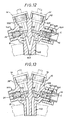
- the valve body above also comprises two lateral ends 144, 145, substantially opposite, which are arranged one to receive a plug 34, and the other a cartridge C.
- a channel 146 opens into the end piece 144, and downstream of the valve 13B a channel 147 opens out inside the end piece 145, so that each valve 13A, 13B can be operated independently as a function necessities during the various operations, filling, evacuating or using the bottle.
- the gas flow rate is determined by: the pressure existing in the expansion chamber CD, and the section of the calibrated orifice 81, and by the pressure of the operating circuit.
- the pressure in the expansion chamber is determined by the metal bellows 82 adjustable in compression by means of the adjustment screw 87.
Landscapes
- Engineering & Computer Science (AREA)
- Physics & Mathematics (AREA)
- Fluid Mechanics (AREA)
- General Physics & Mathematics (AREA)
- Automation & Control Theory (AREA)
- Mechanical Engineering (AREA)
- General Engineering & Computer Science (AREA)
- Filling Or Discharging Of Gas Storage Vessels (AREA)
- Branch Pipes, Bends, And The Like (AREA)
- Filling Of Jars Or Cans And Processes For Cleaning And Sealing Jars (AREA)
- Devices For Dispensing Beverages (AREA)
Claims (16)
Priority Applications (1)
| Application Number | Priority Date | Filing Date | Title |
|---|---|---|---|
| AT86401744T ATE58021T1 (de) | 1985-08-14 | 1986-08-05 | Durchflussbegrenzungsvorrichtung fuer einen hahn einer flasche fuer unter druck stehendes verfluessigtes oder gepresstes glas. |
Applications Claiming Priority (2)
| Application Number | Priority Date | Filing Date | Title |
|---|---|---|---|
| FR8512381 | 1985-08-14 | ||
| FR8512381A FR2586308B1 (fr) | 1985-08-14 | 1985-08-14 | Dispositif limiteur de debit pour robinets de bouteilles a gaz comprime ou liquefie sous pression |
Publications (2)
| Publication Number | Publication Date |
|---|---|
| EP0214023A1 EP0214023A1 (de) | 1987-03-11 |
| EP0214023B1 true EP0214023B1 (de) | 1990-10-31 |
Family
ID=9322229
Family Applications (1)
| Application Number | Title | Priority Date | Filing Date |
|---|---|---|---|
| EP86401744A Expired - Lifetime EP0214023B1 (de) | 1985-08-14 | 1986-08-05 | Durchflussbegrenzungsvorrichtung für einen Hahn einer Flasche für unter Druck stehendes verflüssigtes oder gepresstes Glas |
Country Status (7)
| Country | Link |
|---|---|
| US (1) | US4802504A (de) |
| EP (1) | EP0214023B1 (de) |
| JP (1) | JPS6241499A (de) |
| AT (1) | ATE58021T1 (de) |
| DE (1) | DE3675297D1 (de) |
| ES (1) | ES2001214A6 (de) |
| FR (1) | FR2586308B1 (de) |
Families Citing this family (13)
| Publication number | Priority date | Publication date | Assignee | Title |
|---|---|---|---|---|
| FR2637957B1 (fr) * | 1988-11-14 | 1992-06-26 | Choukri Mohammad | Clapet limiteur de debit et de pression pour l'equipement des bouteilles de 1 a 6 kg butane |
| JPH0538490U (ja) * | 1991-10-25 | 1993-05-25 | 積水化学工業株式会社 | ガス管分岐継手 |
| US5379761A (en) * | 1993-07-21 | 1995-01-10 | Schuler; Manfred | First stage scuba regulator |
| US5520214A (en) * | 1994-09-12 | 1996-05-28 | Western/Scott Fetzer Company | Regulator and fill valve |
| US5794916A (en) * | 1997-04-25 | 1998-08-18 | Vemco Corporation | High pressure fluid valve sealing apparatus |
| US6311682B1 (en) | 1999-01-22 | 2001-11-06 | Npf Limited | Paintball guns |
| US6474325B2 (en) | 1999-01-22 | 2002-11-05 | Npf Limited | Gas regulator |
| US6615814B1 (en) * | 1999-03-18 | 2003-09-09 | Npf Limited | Paintball guns |
| US20020046747A1 (en) * | 2000-07-06 | 2002-04-25 | Colby Daniel H. | Secondary stage regulator apparatus and method for regulating compressed air thereof |
| FR2846757B1 (fr) * | 2002-10-30 | 2006-07-14 | Framatome Anp | Dispositif passif d'equilibrage de la pression d'un premier et d'un second fluides et utilisation |
| FR2853950B1 (fr) * | 2003-04-15 | 2005-06-17 | Air Liquide Electronics Materi | Robinet pour bouteille de gaz et/ou de liquide comportant un orifice calibre interne |
| DE102013004641A1 (de) * | 2013-03-16 | 2014-09-18 | Festo Ag & Co. Kg | Druckeinstellventil |
| AT17317U1 (de) * | 2019-09-03 | 2021-12-15 | Andreas Zieger Dipl Ing | Druckregelventil |
Family Cites Families (8)
| Publication number | Priority date | Publication date | Assignee | Title |
|---|---|---|---|---|
| US1210891A (en) * | 1915-08-02 | 1917-01-02 | Ashcroft Mfg Company | Pressure-reducing valve. |
| US2160025A (en) * | 1934-11-07 | 1939-05-30 | United Aircraft Corp | Hydraulic control mechanism |
| US2553763A (en) * | 1947-03-11 | 1951-05-22 | Nat Welding Equipment Co | Regulator filter |
| US2906288A (en) * | 1956-07-05 | 1959-09-29 | Specialties Dev Corp | Pressure regulating equipment |
| FR1286061A (fr) * | 1961-01-20 | 1962-03-02 | Pingeot & Cie Ets | Robinet à clapet de sécurité pour bouteille de butane ou d'autre gaz comprimé |
| US4210168A (en) * | 1977-10-17 | 1980-07-01 | Kabushiki Kaisha Neriki | Pressure-responsive valve unit for a fluid container |
| US4263939A (en) * | 1979-04-27 | 1981-04-28 | Modern Engineering Company, Inc. | Single stage regulator with surge reducing valve |
| US4526593A (en) * | 1983-04-04 | 1985-07-02 | International Business Machines Corporation | Restrictor plug device with filter for a gas supply system |
-
1985
- 1985-08-14 FR FR8512381A patent/FR2586308B1/fr not_active Expired
-
1986
- 1986-08-05 AT AT86401744T patent/ATE58021T1/de not_active IP Right Cessation
- 1986-08-05 DE DE8686401744T patent/DE3675297D1/de not_active Expired - Lifetime
- 1986-08-05 EP EP86401744A patent/EP0214023B1/de not_active Expired - Lifetime
- 1986-08-05 US US06/893,356 patent/US4802504A/en not_active Expired - Fee Related
- 1986-08-13 ES ES8601056A patent/ES2001214A6/es not_active Expired
- 1986-08-13 JP JP61188792A patent/JPS6241499A/ja active Pending
Also Published As
| Publication number | Publication date |
|---|---|
| EP0214023A1 (de) | 1987-03-11 |
| DE3675297D1 (de) | 1990-12-06 |
| FR2586308B1 (fr) | 1988-08-26 |
| US4802504A (en) | 1989-02-07 |
| ATE58021T1 (de) | 1990-11-15 |
| JPS6241499A (ja) | 1987-02-23 |
| FR2586308A1 (fr) | 1987-02-20 |
| ES2001214A6 (es) | 1988-05-01 |
Similar Documents
| Publication | Publication Date | Title |
|---|---|---|
| EP0214023B1 (de) | Durchflussbegrenzungsvorrichtung für einen Hahn einer Flasche für unter Druck stehendes verflüssigtes oder gepresstes Glas | |
| EP0811900B1 (de) | Gas-regel- und -verteilungsanordnung für Druckgasbehälter | |
| CA2178573C (fr) | Ensemble robinet/detendeur pour bouteille de gaz et bouteille de gaz equipee d'un tel ensemble | |
| EP0485244B1 (de) | Ausgabeventil für einen Behälter mit einer unter einem Druck eines Gases stehenden Flüssigkeit und mit einem derartigen Ventil versehener Behälter | |
| FR2611843A1 (fr) | Ressort a gaz convertible | |
| FR2706051A1 (fr) | Ensemble de commande de distribution de gaz et bouteille de gaz équipée d'un tel ensemble. | |
| EP2870516A1 (de) | Druckmindererventil mit darin eingebauter restdruckfunktion | |
| EP2250426A1 (de) | Gasabfüll- und ausgabevorrichtung sowie abfüllverfahren | |
| EP3002499B1 (de) | Ventilverschlussvorrichtung durch betätigung eines druckminderventils | |
| FR2727318A1 (fr) | Regulateur pour appareils respiratoires sous-marins | |
| EP0374493A1 (de) | Gasflaschenventil | |
| FR2883621A1 (fr) | Dispositif de protection contre une surpression et sous-ensemble de raccordement en comportant application | |
| EP0428901B1 (de) | Neutralisierbares Reduzierventil | |
| EP0340111B1 (de) | Differential-Auslöseventil für Leitungen von Flüssigkeiten unter Druck | |
| EP4257868A1 (de) | Ventil für einen gasbehälter mit verbessertem integriertem expander | |
| FR2563312A1 (fr) | Soupape de reduction de pression | |
| FR2896724A1 (fr) | Vanne de gonflage, de degonflage et de mesure de la pression dans une capacite | |
| EP1634002B1 (de) | Füll- und leerventil und reinigungsgerät für einen flüssigkeitsdruckbehälter | |
| EP0743489A1 (de) | Gaszufuhreinrichtung, Vorrichtung zur Erzeugung einer Flamme die diese Einrichtung enthält und Druckminderer dafür | |
| FR2922294A1 (fr) | Bouchon et pieces de jonction destines au remplissage ou la distribution de gaz contenu dans des recipients sous pression | |
| LU88490A1 (fr) | Clapet de fermeture pour un extincteur d'incendie | |
| EP3974700A1 (de) | Hahn für gasbehälter mit integriertem druckreduzierer, der mit einem sicherheitsventil ausgestattet ist | |
| FR3140076A1 (fr) | Valve à gazage rapide pour aérosol rechargeable | |
| BE524831A (de) | ||
| EP0351258A2 (de) | Oszillierendes Druckminderventil für gasförmige Medien, insbesondere für Sauerstoff unter hohem Druck |
Legal Events
| Date | Code | Title | Description |
|---|---|---|---|
| PUAI | Public reference made under article 153(3) epc to a published international application that has entered the european phase |
Free format text: ORIGINAL CODE: 0009012 |
|
| 17P | Request for examination filed |
Effective date: 19860809 |
|
| AK | Designated contracting states |
Kind code of ref document: A1 Designated state(s): AT BE CH DE FR GB IT LI LU NL SE |
|
| 17Q | First examination report despatched |
Effective date: 19881114 |
|
| GRAA | (expected) grant |
Free format text: ORIGINAL CODE: 0009210 |
|
| ITF | It: translation for a ep patent filed |
Owner name: BARZANO' E ZANARDO MILANO S.P.A. |
|
| AK | Designated contracting states |
Kind code of ref document: B1 Designated state(s): AT BE CH DE FR GB IT LI LU NL SE |
|
| REF | Corresponds to: |
Ref document number: 58021 Country of ref document: AT Date of ref document: 19901115 Kind code of ref document: T |
|
| GBT | Gb: translation of ep patent filed (gb section 77(6)(a)/1977) | ||
| REF | Corresponds to: |
Ref document number: 3675297 Country of ref document: DE Date of ref document: 19901206 |
|
| PGFP | Annual fee paid to national office [announced via postgrant information from national office to epo] |
Ref country code: FR Payment date: 19910708 Year of fee payment: 6 |
|
| PGFP | Annual fee paid to national office [announced via postgrant information from national office to epo] |
Ref country code: AT Payment date: 19910709 Year of fee payment: 6 |
|
| PGFP | Annual fee paid to national office [announced via postgrant information from national office to epo] |
Ref country code: SE Payment date: 19910712 Year of fee payment: 6 Ref country code: GB Payment date: 19910712 Year of fee payment: 6 |
|
| PGFP | Annual fee paid to national office [announced via postgrant information from national office to epo] |
Ref country code: CH Payment date: 19910716 Year of fee payment: 6 |
|
| PGFP | Annual fee paid to national office [announced via postgrant information from national office to epo] |
Ref country code: LU Payment date: 19910729 Year of fee payment: 6 Ref country code: DE Payment date: 19910729 Year of fee payment: 6 Ref country code: BE Payment date: 19910729 Year of fee payment: 6 |
|
| ITTA | It: last paid annual fee | ||
| PGFP | Annual fee paid to national office [announced via postgrant information from national office to epo] |
Ref country code: NL Payment date: 19910831 Year of fee payment: 6 |
|
| PLBE | No opposition filed within time limit |
Free format text: ORIGINAL CODE: 0009261 |
|
| STAA | Information on the status of an ep patent application or granted ep patent |
Free format text: STATUS: NO OPPOSITION FILED WITHIN TIME LIMIT |
|
| 26N | No opposition filed | ||
| EPTA | Lu: last paid annual fee | ||
| PG25 | Lapsed in a contracting state [announced via postgrant information from national office to epo] |
Ref country code: LU Free format text: LAPSE BECAUSE OF NON-PAYMENT OF DUE FEES Effective date: 19920805 Ref country code: GB Effective date: 19920805 Ref country code: AT Effective date: 19920805 |
|
| PG25 | Lapsed in a contracting state [announced via postgrant information from national office to epo] |
Ref country code: SE Effective date: 19920806 |
|
| PG25 | Lapsed in a contracting state [announced via postgrant information from national office to epo] |
Ref country code: LI Effective date: 19920831 Ref country code: CH Effective date: 19920831 Ref country code: BE Effective date: 19920831 |
|
| BERE | Be: lapsed |
Owner name: S.A. L' AIR LIQUIDE POUR L'ETUDE ET L'EXPLOITATION Effective date: 19920831 |
|
| PG25 | Lapsed in a contracting state [announced via postgrant information from national office to epo] |
Ref country code: NL Effective date: 19930301 |
|
| GBPC | Gb: european patent ceased through non-payment of renewal fee |
Effective date: 19920805 |
|
| NLV4 | Nl: lapsed or anulled due to non-payment of the annual fee | ||
| PG25 | Lapsed in a contracting state [announced via postgrant information from national office to epo] |
Ref country code: FR Effective date: 19930430 |
|
| REG | Reference to a national code |
Ref country code: CH Ref legal event code: PL |
|
| PG25 | Lapsed in a contracting state [announced via postgrant information from national office to epo] |
Ref country code: DE Effective date: 19930501 |
|
| REG | Reference to a national code |
Ref country code: FR Ref legal event code: ST |
|
| EUG | Se: european patent has lapsed |
Ref document number: 86401744.7 Effective date: 19930307 |
|
| PG25 | Lapsed in a contracting state [announced via postgrant information from national office to epo] |
Ref country code: IT Free format text: LAPSE BECAUSE OF NON-PAYMENT OF DUE FEES;WARNING: LAPSES OF ITALIAN PATENTS WITH EFFECTIVE DATE BEFORE 2007 MAY HAVE OCCURRED AT ANY TIME BEFORE 2007. THE CORRECT EFFECTIVE DATE MAY BE DIFFERENT FROM THE ONE RECORDED. Effective date: 20050805 |