EP0811537B1 - Verfahren und Vorrichtung zum Waschen von Fahrzeugen - Google Patents
Verfahren und Vorrichtung zum Waschen von Fahrzeugen Download PDFInfo
- Publication number
- EP0811537B1 EP0811537B1 EP97105889A EP97105889A EP0811537B1 EP 0811537 B1 EP0811537 B1 EP 0811537B1 EP 97105889 A EP97105889 A EP 97105889A EP 97105889 A EP97105889 A EP 97105889A EP 0811537 B1 EP0811537 B1 EP 0811537B1
- Authority
- EP
- European Patent Office
- Prior art keywords
- runner
- rotation
- roller
- axis
- wash
- Prior art date
- Legal status (The legal status is an assumption and is not a legal conclusion. Google has not performed a legal analysis and makes no representation as to the accuracy of the status listed.)
- Expired - Lifetime
Links
- 238000005406 washing Methods 0.000 title claims abstract description 57
- 238000000034 method Methods 0.000 title claims description 10
- 230000033001 locomotion Effects 0.000 claims abstract description 22
- 230000000903 blocking effect Effects 0.000 description 2
- 239000004753 textile Substances 0.000 description 2
- 230000005540 biological transmission Effects 0.000 description 1
- 239000006260 foam Substances 0.000 description 1
- 238000000465 moulding Methods 0.000 description 1
- 230000007704 transition Effects 0.000 description 1
Images





Classifications
-
- B—PERFORMING OPERATIONS; TRANSPORTING
- B60—VEHICLES IN GENERAL
- B60S—SERVICING, CLEANING, REPAIRING, SUPPORTING, LIFTING, OR MANOEUVRING OF VEHICLES, NOT OTHERWISE PROVIDED FOR
- B60S3/00—Vehicle cleaning apparatus not integral with vehicles
- B60S3/04—Vehicle cleaning apparatus not integral with vehicles for exteriors of land vehicles
- B60S3/06—Vehicle cleaning apparatus not integral with vehicles for exteriors of land vehicles with rotary bodies contacting the vehicle
- B60S3/066—Vehicle cleaning apparatus not integral with vehicles for exteriors of land vehicles with rotary bodies contacting the vehicle the axis of rotation being approximately horizontal
-
- B—PERFORMING OPERATIONS; TRANSPORTING
- B60—VEHICLES IN GENERAL
- B60S—SERVICING, CLEANING, REPAIRING, SUPPORTING, LIFTING, OR MANOEUVRING OF VEHICLES, NOT OTHERWISE PROVIDED FOR
- B60S3/00—Vehicle cleaning apparatus not integral with vehicles
- B60S3/04—Vehicle cleaning apparatus not integral with vehicles for exteriors of land vehicles
- B60S3/06—Vehicle cleaning apparatus not integral with vehicles for exteriors of land vehicles with rotary bodies contacting the vehicle
- B60S3/063—Vehicle cleaning apparatus not integral with vehicles for exteriors of land vehicles with rotary bodies contacting the vehicle the axis of rotation being approximately vertical
Definitions
- the invention relates to a method for washing Vehicles with at least one around their axis of rotation rotating washing roller, which a variety individual washing elements, such as bristles, rags, strips or the like, in particular a washing brush, where washing roller and vehicle surface essentially perpendicular to the axis of rotation relative to each other be moved.
- the invention further relates to a Device for washing vehicles.
- washing rollers In the usual methods for washing vehicles the washing rollers are simply driven to rotate, which gives a good wash result on smooth surfaces is achieved.
- the foregoing Parts such as slats, moldings, Rear-view mirrors and the like, as well as for recesses, e.g. in the window area, however, zones remain in to whom the dirt is not at all or insufficient Will get removed. These zones are called “wash shadows" designated and are due to the fact that the Wash elements through the protruding parts as well at transitions, seen in the axial direction of the washing roller, spread apart or pushed aside. Through this process, the washing elements e.g. adjacent to longitudinal scraper bars Area or zones above and below the rearview mirror do not brush.
- US-A-3 939 517 describes a method and an apparatus according to the preamble of claims 1 and 4.
- the invention is based on the object Method and device for washing vehicles of the type mentioned at the beginning, with which an improved washing result with extensive Avoiding "wash shadow” is achievable.
- the invention is therefore based on the idea of the rotational movement the washing roller has a short-stroke movement with a low stroke frequency in axial direction Overlay in the direction of the washing roller. Surprisingly the washing result can be greatly improved.
- Through the back and forth Movement of the washing roller will spread the Wash elements on each side of the projecting Partially reduced or eliminated, so that the washing elements can also reach zones that are more immediate Neighborhood of protruding parts or paragraphs lie.
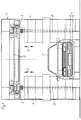
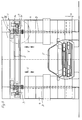
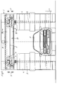
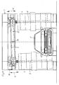
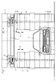
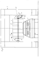
- 1 is a washing portal referred to, which relative to the vehicle F in the Is movable in the longitudinal direction. This means that either as with gantry car washes, the vehicle rests during the washing process and the portal 1 back and forth (perpendicular to the plane of the drawing) or that the portal is idle in car washes and that Vehicle towed through the car wash becomes.
- the portal 1 has horizontal tracks 2 on which two carriages 3 can be moved horizontally are. Because these two carriages are of the same design only one of them is described below.
- Each of the carriages 3 carries a washing roller 4, which can be driven in rotation about a horizontal axis of rotation D. is. Serves to drive the washing roller 4 a drive unit consisting of engine and transmission 5.
- the washing roller 4 has a variety individual washing elements, e.g. Bristles, textile rags, Textile or foam strips, fur strips or the like. on. According to the invention, the washing rollers 4 in Direction V of their axes of rotation D, i.e. in the in the Figures 1 - 12 illustrated embodiments, be vertically reciprocating.
- the stroke h of this back and forth movement of the washing roller 4 can be up to 100 mm.
- a hub is advantageous of about 10-50 mm, preferably about 25 mm.
- the stroke frequency of the washing roller 4 or its holder should be between 0.1-1.0 Hz, preferably about 0.35 Hz, be.
- the back and forth movement of the washing roller 4 can either can be achieved in that the bracket which the Washer roller 4 carries, back and forth as it in the embodiments shown in Figures 1-10 the case is, or that only the washing roller itself pushed back and forth to their drive unit becomes, as in the exemplary embodiments shown in FIGS. 11-14 the case is. If only the washing roller 4 is moved back and forth, this has the advantage that smaller masses have to be moved back and forth.
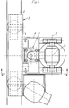
- FIG. 5-7 is a bracket 13 over several parallelogram handlebars 14, 14 'with the carriage 3 vertically movable connected.
- the freewheel has a blocking effect, causing the carriage 3 by means of the now driven impeller 20 to the outside, i.e. is moved to the side of the portal.
- the carriage is towards the center of the portal by attacking a cable, not shown Weight loaded.
- a control cam 21 firmly connected to the an extension 14a of the parallelogram link 14 ' acts.
- the servomotor 15 is operated by a suitable known control device controlled depending from the contact pressure of the washing roller 4 to the washing vehicle F the servomotor 15 in one or switches on the other direction of rotation.
- the control device can be an ammeter, a power meter, a tachometer, a tilt switch or the like.
- the servomotor 15 turned on in a first direction of rotation, which the output shaft 18 against the arrow direction A drives.
- the drive connection is in this direction of rotation to the impeller 20 interrupted by the freewheel 19.
- the firmly connected to the output shaft 18 Control cam 21 thus constantly displaces the bracket in an up and down movement with the stroke h. This Movement is from the bracket 13 via the pivot shaft S on the bearing housing 9 and from this to the Transfer washing roller 4.
- FIG. 8 and 9 are the rails 2 of the carriage 3 arranged on a running rail support 22.
- This track carrier 22 is on by means of vertical guides 23 the portal 1 is mounted so that it can move.
- a drive motor 24 drives a connecting shaft 25, on the A control cam 26 is arranged at both ends is.
- Each of these control cams acts on one the rail support 22 connected arm 27.
- a stroke h is given in the direction V, whereby the washing roller 4 to the same extent in Direction V is moved up and down.
- running rails 2 on a running rail carrier 22 ' arranged in its central area by one horizontal arranged transversely to its longitudinal direction Swivel axis 28 is pivotable.
- a suitable Drive motor 29 becomes the running rail support 22 ', as indicated by the arrows G, swung up and down, making the washing rollers 4 a substantially vertical running up and down movement in the direction of their axes of rotation is granted.
- the rails 2 are fixed to the portal 1 connected and the carriage 3 on the rails 2 movable.
- the bearing housing 9 is about the pivot axis S pivoted on the carriage 3.
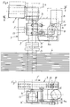
- the washing roller 4 has a central Support tube 30, which on a rotatable connected to the drive unit 5 drive shaft 31 is axially displaceable.
- a groove drum 32 With the top of the Carrier tube 30, a groove drum 32 is firmly connected, which is wavy in the circumferential direction Control groove 33 has.
- Via a sliding block 34 the engages in an axial groove 35 of the drive shaft 31, the support tube 30 is non-rotatable, but axially displaceable connected to the drive shaft 31.
- a roll 36 which is arranged at the lower end of the support rod 37, engages in the control groove 33.
- the support rod 37 is firmly connected to the bearing housing 9.
- the role 36 can also be replaced by a sliding block. If the drive shaft 31 via the drive unit 5 is driven in rotation, then the grooved drum rotates 32 relative to the stationary roller 36. Die undulating control groove 33 causes a Up and down movement of the grooved drum and thus the firmly connected to the support tube 30 of the washing roller 4th
- the axis of rotation D of the washing roller 4 is arranged horizontally.
- the washing roller 4 is similar to in the embodiment shown in Figures 11 and 12 provided with a central support tube 30, which compared to the drive shaft, not shown, which are driven by the drive unit 5 is axially displaceable, but non-rotatably connected is.
- a groove drum 32 attached, the one in Circumferential direction of wavy control groove 33 having.
- FIG. 14 In the embodiment shown in Figure 14 is the support tube that can be moved on the drive shaft connected to a sleeve 40 which is a circumferential Control groove 41 has.
- This control groove 41 engages a roller 42 which at the free end of a pivotable Control arm 43 is arranged.
- the control arm 43 is pivotable about axis S2 with that in portal 1 height-adjustable lifting carriage 45 connected.
- a Drive motor 46 is also on this lifting carriage 45 arranged and the control arm 43 in a Swivel motion which is a reciprocating motion of the Wash roller 4 offset in the direction H of its axis of rotation.
Landscapes
- Engineering & Computer Science (AREA)
- Mechanical Engineering (AREA)
- Vehicle Cleaning, Maintenance, Repair, Refitting, And Outriggers (AREA)
- Cleaning By Liquid Or Steam (AREA)
Applications Claiming Priority (2)
| Application Number | Priority Date | Filing Date | Title |
|---|---|---|---|
| DE29610107U | 1996-06-08 | ||
| DE29610107U DE29610107U1 (de) | 1996-06-08 | 1996-06-08 | Vorrichtung zum Waschen von Fahrzeugen |
Publications (2)
| Publication Number | Publication Date |
|---|---|
| EP0811537A1 EP0811537A1 (de) | 1997-12-10 |
| EP0811537B1 true EP0811537B1 (de) | 1999-08-25 |
Family
ID=8024940
Family Applications (1)
| Application Number | Title | Priority Date | Filing Date |
|---|---|---|---|
| EP97105889A Expired - Lifetime EP0811537B1 (de) | 1996-06-08 | 1997-04-10 | Verfahren und Vorrichtung zum Waschen von Fahrzeugen |
Country Status (6)
| Country | Link |
|---|---|
| EP (1) | EP0811537B1 (da) |
| AT (1) | ATE183699T1 (da) |
| DE (2) | DE29610107U1 (da) |
| DK (1) | DK0811537T3 (da) |
| ES (1) | ES2137033T3 (da) |
| NO (1) | NO311248B1 (da) |
Cited By (1)
| Publication number | Priority date | Publication date | Assignee | Title |
|---|---|---|---|---|
| DE102019101052A1 (de) | 2019-01-16 | 2020-07-16 | René Stegemann | Vorrichtung zum Waschen eines Fahrzeugs |
Families Citing this family (2)
| Publication number | Priority date | Publication date | Assignee | Title |
|---|---|---|---|---|
| DE29718402U1 (de) * | 1997-10-16 | 1999-02-11 | Wesumat Fahrzeugwaschanlagen GmbH, 86156 Augsburg | Vorrichtung zum Waschen oder Polieren von Fahrzeugen |
| US8601632B2 (en) * | 2010-11-18 | 2013-12-10 | N/S Corporation | Vehicle washing apparatus with a movable brush arm carriage |
Family Cites Families (3)
| Publication number | Priority date | Publication date | Assignee | Title |
|---|---|---|---|---|
| US3939517A (en) * | 1973-11-29 | 1976-02-24 | Bivens David J | Overhead brush system with lateral movement |
| IT1188745B (it) * | 1986-05-28 | 1988-01-28 | Favagrossa Edoardo & Figlio | Struttura di spazzolone rotante,per impianti di autolavaggio,provvisto di gruppo di setole aventi lunghezza differenziate e disposte in moda da operare,sulla carrozzeria di un autoveicolo,secondo un movimento formalmente sinusoiale |
| US5361443A (en) * | 1993-04-27 | 1994-11-08 | Belanger, Inc. | Elastic coupling for a car wash rotary wheel assembly |
-
1996
- 1996-06-08 DE DE29610107U patent/DE29610107U1/de not_active Expired - Lifetime
-
1997
- 1997-04-10 DK DK97105889T patent/DK0811537T3/da active
- 1997-04-10 DE DE59700361T patent/DE59700361D1/de not_active Expired - Fee Related
- 1997-04-10 ES ES97105889T patent/ES2137033T3/es not_active Expired - Lifetime
- 1997-04-10 EP EP97105889A patent/EP0811537B1/de not_active Expired - Lifetime
- 1997-04-10 AT AT97105889T patent/ATE183699T1/de not_active IP Right Cessation
- 1997-06-06 NO NO19972618A patent/NO311248B1/no unknown
Cited By (1)
| Publication number | Priority date | Publication date | Assignee | Title |
|---|---|---|---|---|
| DE102019101052A1 (de) | 2019-01-16 | 2020-07-16 | René Stegemann | Vorrichtung zum Waschen eines Fahrzeugs |
Also Published As
| Publication number | Publication date |
|---|---|
| DE59700361D1 (de) | 1999-09-30 |
| NO311248B1 (no) | 2001-11-05 |
| EP0811537A1 (de) | 1997-12-10 |
| ATE183699T1 (de) | 1999-09-15 |
| NO972618D0 (no) | 1997-06-06 |
| ES2137033T3 (es) | 1999-12-01 |
| NO972618L (no) | 1997-12-09 |
| DE29610107U1 (de) | 1997-11-13 |
| DK0811537T3 (da) | 2000-01-31 |
Similar Documents
| Publication | Publication Date | Title |
|---|---|---|
| DE19751016C2 (de) | Verfahren und Portalwaschanlage zum Waschen von Kraftfahrzeugen | |
| EP0637531B1 (de) | Vorrichtung zum Reinigen eines Zweirades, insbesondere eines Fahrrades | |
| DE2426796A1 (de) | Verfahren und vorrichtung zum automatischen waschen von fahrzeugen | |
| DE202016101927U1 (de) | Bürstenschwenkvorrichtung, Seitenwaschbürste und damit ausgestattete Fahrzeugwaschanlage | |
| EP0811537B1 (de) | Verfahren und Vorrichtung zum Waschen von Fahrzeugen | |
| DE19524748C2 (de) | Waschvorrichtung für eine Fahrzeug-Waschstraße | |
| DE69105929T2 (de) | Auf einem einzigen beweglichen Portal aufgebautes vollständiges und schnelles Waschsystem. | |
| EP3475129A1 (de) | Trocknungsvorrichtung für kraftfahrzeuge und fahrzeugwaschanlage mit einer trocknungsvorrichtung | |
| EP0926029A2 (de) | Unterboden-Waschvorrichtung für Kraftfahrzeuge | |
| EP0808754B1 (de) | Verfahren und Vorrichtung zum Waschen von Fahrzeugen | |
| DE2516609B2 (de) | Waschanlage zum Reinigen von Fahrzeugkarosserien | |
| DE19623000C2 (de) | Vorrichtung zum Waschen von Fahrzeugen | |
| DE69004502T2 (de) | Fahrzeugwaschanlage mit beinahe elliptischen zylindrischen Bürsten die auf in Längsrichtung waagerechten Achsen drehen. | |
| EP1106457A2 (de) | Kraftfahrzeug-Waschstrasse | |
| EP0103222B1 (de) | Waschvorrichtung für Fahrzeuge, insbesondere Omnibusse und Kastenwagen | |
| DE4025413C2 (da) | ||
| DE19524443C2 (de) | Waschvorrichtung für Fahrzeugräder | |
| DE10206490C1 (de) | Vorrichtung zum Behandeln der Oberfläche von Fahrzeugen | |
| DE29509750U1 (de) | Fahrzeugwaschanlage | |
| DE2223994A1 (de) | Waschvorrichtung fuer durchlaufende kraftfahrzeuge | |
| EP0911233B1 (de) | Vorrichtung zum Waschen oder Polieren von Fahrzeugen | |
| DE1455648B1 (de) | Vorrichtung zum Waschen der Seiten- und Stirnflächen eines Fahrzeuges | |
| DE8814002U1 (de) | Fahrzeug-Wasch-, Polier- oder Trocknungsvorrichtung | |
| DE19745745C1 (de) | Vorrichtung zum Waschen oder Polieren von Fahrzeugen | |
| DE29511028U1 (de) | Waschvorrichtung für eine Fahrzeug-Waschstraße |
Legal Events
| Date | Code | Title | Description |
|---|---|---|---|
| PUAI | Public reference made under article 153(3) epc to a published international application that has entered the european phase |
Free format text: ORIGINAL CODE: 0009012 |
|
| AK | Designated contracting states |
Kind code of ref document: A1 Designated state(s): AT BE CH DE DK ES FI FR GB IT LI LU NL PT SE |
|
| AX | Request for extension of the european patent |
Free format text: LT PAYMENT 970410;LV PAYMENT 970410;SI PAYMENT 970410 |
|
| 17P | Request for examination filed |
Effective date: 19980113 |
|
| 17Q | First examination report despatched |
Effective date: 19980302 |
|
| GRAG | Despatch of communication of intention to grant |
Free format text: ORIGINAL CODE: EPIDOS AGRA |
|
| GRAG | Despatch of communication of intention to grant |
Free format text: ORIGINAL CODE: EPIDOS AGRA |
|
| GRAH | Despatch of communication of intention to grant a patent |
Free format text: ORIGINAL CODE: EPIDOS IGRA |
|
| GRAH | Despatch of communication of intention to grant a patent |
Free format text: ORIGINAL CODE: EPIDOS IGRA |
|
| GRAA | (expected) grant |
Free format text: ORIGINAL CODE: 0009210 |
|
| AK | Designated contracting states |
Kind code of ref document: B1 Designated state(s): AT BE CH DE DK ES FI FR GB IT LI LU NL PT SE |
|
| AX | Request for extension of the european patent |
Free format text: LT PAYMENT 19970410;LV PAYMENT 19970410;SI PAYMENT 19970410 |
|
| LTIE | Lt: invalidation of european patent or patent extension | ||
| REF | Corresponds to: |
Ref document number: 183699 Country of ref document: AT Date of ref document: 19990915 Kind code of ref document: T |
|
| REG | Reference to a national code |
Ref country code: CH Ref legal event code: EP |
|
| REF | Corresponds to: |
Ref document number: 59700361 Country of ref document: DE Date of ref document: 19990930 |
|
| REG | Reference to a national code |
Ref country code: CH Ref legal event code: NV Representative=s name: DIPL.-ING. W. STEUDTNER |
|
| ITF | It: translation for a ep patent filed | ||
| GBT | Gb: translation of ep patent filed (gb section 77(6)(a)/1977) |
Effective date: 19991109 |
|
| REG | Reference to a national code |
Ref country code: ES Ref legal event code: FG2A Ref document number: 2137033 Country of ref document: ES Kind code of ref document: T3 |
|
| ET | Fr: translation filed | ||
| REG | Reference to a national code |
Ref country code: DK Ref legal event code: T3 Ref country code: PT Ref legal event code: SC4A Free format text: AVAILABILITY OF NATIONAL TRANSLATION Effective date: 19991105 |
|
| PGFP | Annual fee paid to national office [announced via postgrant information from national office to epo] |
Ref country code: PT Payment date: 20000308 Year of fee payment: 4 |
|
| PGFP | Annual fee paid to national office [announced via postgrant information from national office to epo] |
Ref country code: FR Payment date: 20000309 Year of fee payment: 4 |
|
| PGFP | Annual fee paid to national office [announced via postgrant information from national office to epo] |
Ref country code: SE Payment date: 20000310 Year of fee payment: 4 |
|
| PGFP | Annual fee paid to national office [announced via postgrant information from national office to epo] |
Ref country code: LU Payment date: 20000323 Year of fee payment: 4 |
|
| PGFP | Annual fee paid to national office [announced via postgrant information from national office to epo] |
Ref country code: ES Payment date: 20000324 Year of fee payment: 4 |
|
| PGFP | Annual fee paid to national office [announced via postgrant information from national office to epo] |
Ref country code: AT Payment date: 20000327 Year of fee payment: 4 |
|
| PGFP | Annual fee paid to national office [announced via postgrant information from national office to epo] |
Ref country code: BE Payment date: 20000328 Year of fee payment: 4 |
|
| PGFP | Annual fee paid to national office [announced via postgrant information from national office to epo] |
Ref country code: DK Payment date: 20000410 Year of fee payment: 4 |
|
| PGFP | Annual fee paid to national office [announced via postgrant information from national office to epo] |
Ref country code: FI Payment date: 20000427 Year of fee payment: 4 |
|
| PLBE | No opposition filed within time limit |
Free format text: ORIGINAL CODE: 0009261 |
|
| STAA | Information on the status of an ep patent application or granted ep patent |
Free format text: STATUS: NO OPPOSITION FILED WITHIN TIME LIMIT |
|
| 26N | No opposition filed | ||
| PG25 | Lapsed in a contracting state [announced via postgrant information from national office to epo] |
Ref country code: LU Free format text: LAPSE BECAUSE OF NON-PAYMENT OF DUE FEES Effective date: 20010410 Ref country code: GB Free format text: LAPSE BECAUSE OF NON-PAYMENT OF DUE FEES Effective date: 20010410 Ref country code: FI Free format text: LAPSE BECAUSE OF NON-PAYMENT OF DUE FEES Effective date: 20010410 Ref country code: DK Free format text: LAPSE BECAUSE OF NON-PAYMENT OF DUE FEES Effective date: 20010410 Ref country code: AT Free format text: LAPSE BECAUSE OF NON-PAYMENT OF DUE FEES Effective date: 20010410 |
|
| PG25 | Lapsed in a contracting state [announced via postgrant information from national office to epo] |
Ref country code: SE Free format text: LAPSE BECAUSE OF NON-PAYMENT OF DUE FEES Effective date: 20010411 Ref country code: ES Free format text: LAPSE BECAUSE OF NON-PAYMENT OF DUE FEES Effective date: 20010411 |
|
| PG25 | Lapsed in a contracting state [announced via postgrant information from national office to epo] |
Ref country code: FR Free format text: THE PATENT HAS BEEN ANNULLED BY A DECISION OF A NATIONAL AUTHORITY Effective date: 20010430 Ref country code: BE Free format text: LAPSE BECAUSE OF NON-PAYMENT OF DUE FEES Effective date: 20010430 |
|
| PG25 | Lapsed in a contracting state [announced via postgrant information from national office to epo] |
Ref country code: LI Free format text: LAPSE BECAUSE OF NON-PAYMENT OF DUE FEES Effective date: 20010509 Ref country code: CH Free format text: LAPSE BECAUSE OF NON-PAYMENT OF DUE FEES Effective date: 20010509 |
|
| BERE | Be: lapsed |
Owner name: WESUMAT FAHRZEUGWASCHANLAGEN G.M.B.H. Effective date: 20010430 |
|
| PG25 | Lapsed in a contracting state [announced via postgrant information from national office to epo] |
Ref country code: PT Free format text: LAPSE BECAUSE OF NON-PAYMENT OF DUE FEES Effective date: 20011031 |
|
| PG25 | Lapsed in a contracting state [announced via postgrant information from national office to epo] |
Ref country code: NL Free format text: LAPSE BECAUSE OF NON-PAYMENT OF DUE FEES Effective date: 20011101 |
|
| GBPC | Gb: european patent ceased through non-payment of renewal fee |
Effective date: 20010410 |
|
| EUG | Se: european patent has lapsed |
Ref document number: 97105889.6 |
|
| REG | Reference to a national code |
Ref country code: DK Ref legal event code: EBP |
|
| REG | Reference to a national code |
Ref country code: CH Ref legal event code: PL |
|
| NLV4 | Nl: lapsed or anulled due to non-payment of the annual fee |
Effective date: 20011101 |
|
| REG | Reference to a national code |
Ref country code: FR Ref legal event code: ST |
|
| REG | Reference to a national code |
Ref country code: PT Ref legal event code: MM4A Free format text: LAPSE DUE TO NON-PAYMENT OF FEES Effective date: 20011031 |
|
| PGFP | Annual fee paid to national office [announced via postgrant information from national office to epo] |
Ref country code: DE Payment date: 20020618 Year of fee payment: 6 |
|
| REG | Reference to a national code |
Ref country code: ES Ref legal event code: FD2A Effective date: 20030203 |
|
| PG25 | Lapsed in a contracting state [announced via postgrant information from national office to epo] |
Ref country code: DE Free format text: LAPSE BECAUSE OF NON-PAYMENT OF DUE FEES Effective date: 20031101 |
|
| PG25 | Lapsed in a contracting state [announced via postgrant information from national office to epo] |
Ref country code: IT Free format text: LAPSE BECAUSE OF NON-PAYMENT OF DUE FEES Effective date: 20050410 |
|
| REG | Reference to a national code |
Ref country code: DE Ref legal event code: R082 Ref document number: 59700361 Country of ref document: DE |