EP0811537B1 - Process and device for washing vehicles - Google Patents
Process and device for washing vehicles Download PDFInfo
- Publication number
- EP0811537B1 EP0811537B1 EP97105889A EP97105889A EP0811537B1 EP 0811537 B1 EP0811537 B1 EP 0811537B1 EP 97105889 A EP97105889 A EP 97105889A EP 97105889 A EP97105889 A EP 97105889A EP 0811537 B1 EP0811537 B1 EP 0811537B1
- Authority
- EP
- European Patent Office
- Prior art keywords
- runner
- rotation
- roller
- axis
- wash
- Prior art date
- Legal status (The legal status is an assumption and is not a legal conclusion. Google has not performed a legal analysis and makes no representation as to the accuracy of the status listed.)
- Expired - Lifetime
Links
Images


Classifications
-
- B—PERFORMING OPERATIONS; TRANSPORTING
- B60—VEHICLES IN GENERAL
- B60S—SERVICING, CLEANING, REPAIRING, SUPPORTING, LIFTING, OR MANOEUVRING OF VEHICLES, NOT OTHERWISE PROVIDED FOR
- B60S3/00—Vehicle cleaning apparatus not integral with vehicles
- B60S3/04—Vehicle cleaning apparatus not integral with vehicles for exteriors of land vehicles
- B60S3/06—Vehicle cleaning apparatus not integral with vehicles for exteriors of land vehicles with rotary bodies contacting the vehicle
- B60S3/066—Vehicle cleaning apparatus not integral with vehicles for exteriors of land vehicles with rotary bodies contacting the vehicle the axis of rotation being approximately horizontal
-
- B—PERFORMING OPERATIONS; TRANSPORTING
- B60—VEHICLES IN GENERAL
- B60S—SERVICING, CLEANING, REPAIRING, SUPPORTING, LIFTING, OR MANOEUVRING OF VEHICLES, NOT OTHERWISE PROVIDED FOR
- B60S3/00—Vehicle cleaning apparatus not integral with vehicles
- B60S3/04—Vehicle cleaning apparatus not integral with vehicles for exteriors of land vehicles
- B60S3/06—Vehicle cleaning apparatus not integral with vehicles for exteriors of land vehicles with rotary bodies contacting the vehicle
- B60S3/063—Vehicle cleaning apparatus not integral with vehicles for exteriors of land vehicles with rotary bodies contacting the vehicle the axis of rotation being approximately vertical
Definitions
- the invention relates to a method for washing Vehicles with at least one around their axis of rotation rotating washing roller, which a variety individual washing elements, such as bristles, rags, strips or the like, in particular a washing brush, where washing roller and vehicle surface essentially perpendicular to the axis of rotation relative to each other be moved.
- the invention further relates to a Device for washing vehicles.
- washing rollers In the usual methods for washing vehicles the washing rollers are simply driven to rotate, which gives a good wash result on smooth surfaces is achieved.
- the foregoing Parts such as slats, moldings, Rear-view mirrors and the like, as well as for recesses, e.g. in the window area, however, zones remain in to whom the dirt is not at all or insufficient Will get removed. These zones are called “wash shadows" designated and are due to the fact that the Wash elements through the protruding parts as well at transitions, seen in the axial direction of the washing roller, spread apart or pushed aside. Through this process, the washing elements e.g. adjacent to longitudinal scraper bars Area or zones above and below the rearview mirror do not brush.
- US-A-3 939 517 describes a method and an apparatus according to the preamble of claims 1 and 4.
- the invention is based on the object Method and device for washing vehicles of the type mentioned at the beginning, with which an improved washing result with extensive Avoiding "wash shadow” is achievable.
- the invention is therefore based on the idea of the rotational movement the washing roller has a short-stroke movement with a low stroke frequency in axial direction Overlay in the direction of the washing roller. Surprisingly the washing result can be greatly improved.
- Through the back and forth Movement of the washing roller will spread the Wash elements on each side of the projecting Partially reduced or eliminated, so that the washing elements can also reach zones that are more immediate Neighborhood of protruding parts or paragraphs lie.
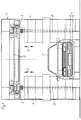
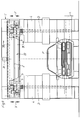
- 1 is a washing portal referred to, which relative to the vehicle F in the Is movable in the longitudinal direction. This means that either as with gantry car washes, the vehicle rests during the washing process and the portal 1 back and forth (perpendicular to the plane of the drawing) or that the portal is idle in car washes and that Vehicle towed through the car wash becomes.
- the portal 1 has horizontal tracks 2 on which two carriages 3 can be moved horizontally are. Because these two carriages are of the same design only one of them is described below.
- Each of the carriages 3 carries a washing roller 4, which can be driven in rotation about a horizontal axis of rotation D. is. Serves to drive the washing roller 4 a drive unit consisting of engine and transmission 5.
- the washing roller 4 has a variety individual washing elements, e.g. Bristles, textile rags, Textile or foam strips, fur strips or the like. on. According to the invention, the washing rollers 4 in Direction V of their axes of rotation D, i.e. in the in the Figures 1 - 12 illustrated embodiments, be vertically reciprocating.
- the stroke h of this back and forth movement of the washing roller 4 can be up to 100 mm.
- a hub is advantageous of about 10-50 mm, preferably about 25 mm.
- the stroke frequency of the washing roller 4 or its holder should be between 0.1-1.0 Hz, preferably about 0.35 Hz, be.
- the back and forth movement of the washing roller 4 can either can be achieved in that the bracket which the Washer roller 4 carries, back and forth as it in the embodiments shown in Figures 1-10 the case is, or that only the washing roller itself pushed back and forth to their drive unit becomes, as in the exemplary embodiments shown in FIGS. 11-14 the case is. If only the washing roller 4 is moved back and forth, this has the advantage that smaller masses have to be moved back and forth.
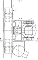
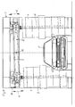
- FIG. 5-7 is a bracket 13 over several parallelogram handlebars 14, 14 'with the carriage 3 vertically movable connected.
- the freewheel has a blocking effect, causing the carriage 3 by means of the now driven impeller 20 to the outside, i.e. is moved to the side of the portal.
- the carriage is towards the center of the portal by attacking a cable, not shown Weight loaded.
- a control cam 21 firmly connected to the an extension 14a of the parallelogram link 14 ' acts.
- the servomotor 15 is operated by a suitable known control device controlled depending from the contact pressure of the washing roller 4 to the washing vehicle F the servomotor 15 in one or switches on the other direction of rotation.
- the control device can be an ammeter, a power meter, a tachometer, a tilt switch or the like.
- the servomotor 15 turned on in a first direction of rotation, which the output shaft 18 against the arrow direction A drives.
- the drive connection is in this direction of rotation to the impeller 20 interrupted by the freewheel 19.
- the firmly connected to the output shaft 18 Control cam 21 thus constantly displaces the bracket in an up and down movement with the stroke h. This Movement is from the bracket 13 via the pivot shaft S on the bearing housing 9 and from this to the Transfer washing roller 4.
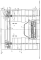
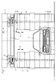
- FIG. 8 and 9 are the rails 2 of the carriage 3 arranged on a running rail support 22.
- This track carrier 22 is on by means of vertical guides 23 the portal 1 is mounted so that it can move.
- a drive motor 24 drives a connecting shaft 25, on the A control cam 26 is arranged at both ends is.
- Each of these control cams acts on one the rail support 22 connected arm 27.
- a stroke h is given in the direction V, whereby the washing roller 4 to the same extent in Direction V is moved up and down.
- running rails 2 on a running rail carrier 22 ' arranged in its central area by one horizontal arranged transversely to its longitudinal direction Swivel axis 28 is pivotable.
- a suitable Drive motor 29 becomes the running rail support 22 ', as indicated by the arrows G, swung up and down, making the washing rollers 4 a substantially vertical running up and down movement in the direction of their axes of rotation is granted.
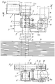
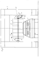
- the rails 2 are fixed to the portal 1 connected and the carriage 3 on the rails 2 movable.
- the bearing housing 9 is about the pivot axis S pivoted on the carriage 3.
- the washing roller 4 has a central Support tube 30, which on a rotatable connected to the drive unit 5 drive shaft 31 is axially displaceable.
- a groove drum 32 With the top of the Carrier tube 30, a groove drum 32 is firmly connected, which is wavy in the circumferential direction Control groove 33 has.
- Via a sliding block 34 the engages in an axial groove 35 of the drive shaft 31, the support tube 30 is non-rotatable, but axially displaceable connected to the drive shaft 31.
- a roll 36 which is arranged at the lower end of the support rod 37, engages in the control groove 33.
- the support rod 37 is firmly connected to the bearing housing 9.
- the role 36 can also be replaced by a sliding block. If the drive shaft 31 via the drive unit 5 is driven in rotation, then the grooved drum rotates 32 relative to the stationary roller 36. Die undulating control groove 33 causes a Up and down movement of the grooved drum and thus the firmly connected to the support tube 30 of the washing roller 4th
- the axis of rotation D of the washing roller 4 is arranged horizontally.
- the washing roller 4 is similar to in the embodiment shown in Figures 11 and 12 provided with a central support tube 30, which compared to the drive shaft, not shown, which are driven by the drive unit 5 is axially displaceable, but non-rotatably connected is.
- a groove drum 32 attached, the one in Circumferential direction of wavy control groove 33 having.
- FIG. 14 In the embodiment shown in Figure 14 is the support tube that can be moved on the drive shaft connected to a sleeve 40 which is a circumferential Control groove 41 has.
- This control groove 41 engages a roller 42 which at the free end of a pivotable Control arm 43 is arranged.
- the control arm 43 is pivotable about axis S2 with that in portal 1 height-adjustable lifting carriage 45 connected.
- a Drive motor 46 is also on this lifting carriage 45 arranged and the control arm 43 in a Swivel motion which is a reciprocating motion of the Wash roller 4 offset in the direction H of its axis of rotation.
Abstract
Description
Die Erfindung betrifft ein Verfahren zum Waschen von Fahrzeugen mit mindestens einer um ihre Drehachse rotierenden Waschwalze, welche eine Vielzahl einzelner Waschelemente, wie Borsten, Lappen, Streifen oder dgl. aufweist, insbesondere einer Waschbürste, wobei Waschwalze und Fahrzeugoberfläche im wesentlichen senkrecht zur Drehachse relativ zueinander bewegt werden. Die Erfindung betrifft ferner eine Vorrichtung zum Waschen von Fahrzeugen.The invention relates to a method for washing Vehicles with at least one around their axis of rotation rotating washing roller, which a variety individual washing elements, such as bristles, rags, strips or the like, in particular a washing brush, where washing roller and vehicle surface essentially perpendicular to the axis of rotation relative to each other be moved. The invention further relates to a Device for washing vehicles.
Bei den bisher üblichen Verfahren zum Waschen von Fahrzeugen werden die Waschwalzen einfach rotierend angetrieben, wodurch an glatten Flächen ein gutes Waschergebnis erzielt wird. In unmittelbarer Nähe von vorstehenden Teilen, wie Schrammleisten, Zierleisten, Rückspiegeln und dgl. sowie auch bei Vertiefungen, z.B. im Fensterbereich, verbleiben jedoch Zonen, in denen der Schmutz überhaupt nicht oder ungenügend entfernt wird. Diese Zonen werden als "Waschschatten" bezeichnet und sind darauf zurückzuführen, daß die Waschelemente durch die vorstehenden Teile sowie auch an Übergängen, in axialer Richtung der Waschwalze gesehen, aufgespreizt bzw. zur Seite gedrängt werden. Durch diesen Vorgang können die Waschelemente den z.B. an längs verlaufende Schrammleisten angrenzenden Bereich oder Zonen oberhalb und unterhalb des Rückspiegels nicht bestreichen.In the usual methods for washing vehicles the washing rollers are simply driven to rotate, which gives a good wash result on smooth surfaces is achieved. In the immediate vicinity of the foregoing Parts, such as slats, moldings, Rear-view mirrors and the like, as well as for recesses, e.g. in the window area, however, zones remain in to whom the dirt is not at all or insufficient Will get removed. These zones are called "wash shadows" designated and are due to the fact that the Wash elements through the protruding parts as well at transitions, seen in the axial direction of the washing roller, spread apart or pushed aside. Through this process, the washing elements e.g. adjacent to longitudinal scraper bars Area or zones above and below the rearview mirror do not brush.
Die US-A-3 939 517 beschreibt ein Verfahren und eine Vorrichtung
gemäß dem Oberbegriff der Ansprüche 1 und 4.US-A-3 939 517 describes a method and an apparatus
according to the preamble of
Der Erfindung liegt die Aufgabe zugrunde, ein Verfahren und eine Vorrichtung zum Waschen von Fahrzeugen der eingangs erwähnten Art aufzuzeigen, mit denen ein verbessertes Waschergebnis unter weitgehender Vermeidung von "Waschschatten" erzielbar ist. The invention is based on the object Method and device for washing vehicles of the type mentioned at the beginning, with which an improved washing result with extensive Avoiding "wash shadow" is achievable.
Dies wird nach der Erfindung
mit den Merkmalen der Ansprüche 1 und 4 erreicht.This is according to the invention
achieved with the features of
Die Erfindung geht also von dem Gedanken aus, der Rotationsbewegung der Waschwalze eine kurzhubige Bewegung geringer Hubfrequenz in axialer Richtung der Waschwalze zu überlagern. Überraschenderweise kann hierdurch das Waschergebnis stark verbessert werden. Dabei werden die Nachbarbereiche von Zier- und Schrammleisten, eingezogene Teile im Fensterbereich, Zonen über und unter dem Rückspiegel, an Regenrinnen und sonstige Vertiefungen angrenzende Bereiche, sowie auch z.B. die oberen und unteren Flächen von Stoßstangen, einwandfrei gereinigt. Durch die hin- und hergehende Bewegung der Waschwalze wird das Aufspreizen der Waschelemente jeweils an einer Seite des vorspringenden Teiles verringert bzw. beseitigt, so daß dann die Waschelemente auch Zonen erreichen können, die in umittelbarer Nachbarschaft von vorspringenden Teilen oder Absätzen liegen. The invention is therefore based on the idea of the rotational movement the washing roller has a short-stroke movement with a low stroke frequency in axial direction Overlay in the direction of the washing roller. Surprisingly the washing result can be greatly improved. The neighboring areas of ornamental and Scraper strips, drawn-in parts in the window area, Zones above and below the rear view mirror, on gutters and other deepening adjacent areas, as well also e.g. the top and bottom surfaces of bumpers, cleaned perfectly. Through the back and forth Movement of the washing roller will spread the Wash elements on each side of the projecting Partially reduced or eliminated, so that the washing elements can also reach zones that are more immediate Neighborhood of protruding parts or paragraphs lie.
Vorteilhafte Ausgestaltungen der Erfindung sind in den Unteransprüchen gekennzeichnet.Advantageous embodiments of the invention are in the Subclaims marked.
Die Erfindung ist in folgendem, anhand von mehreren in der Zeichnung dargestellten Ausführungsbeispielen näher erläutert. Es zeigen:
Figur 1- die Stirnansicht eines Waschportals mit einer ersten Ausführungsform der erfindungsgemäßen Vorrichtung,
Figur 2- einen horizontalen Teilquerschnitt dieser
Vorrichtung im Bereich eines Laufwagens nach
der Linie II-II der
Figur 3, Figur 3- einen vertikalen Teilquerschnitt und eine
Teilseitenansicht nach der Linie III-III
der
Figur 2, Figur 4- eine Teilseitenansicht einer zweiten Ausführungsform im Bereich des Laufwagens,
Figur 5- eine Stirnansicht des Waschportals mit einer dritten Ausführungsform der erfindungsgemäßen Vorrichtung,
Figur 6- eine Teilstirnansicht im Bereich VI der
Figur 5, - Figur 7
- einen horizontalen Teilschnitt nach der
Linie VII-VII der
Figur 6, Figur 8- die Stirnansicht des Waschportals mit einer vierten Ausführungsform der erfindungsgemäßen Vorrichtung,
Figur 9- einen vertikalen Teilschnitt nach der Linie
IX-IX der
Figur 8, Figur 10- die Stirnansicht eines Waschportals mit einer fünften Ausführungsform der erfindungsgemäßen Vorrichtung,
Figur 11- die Stirnansicht des Waschportals mit einer sechsten Ausführungsform der erfindungsgemäßen Vorrichtung,
- Figur 12
- einen vertikalen Teilquerschnitt nach der
Linie XII-XII der
Figur 11, Figur 13- die Stirnansicht des Waschportals mit einer um eine horizontale Achse rotierenden Waschwalze,
Figur 14- die Stirnansicht einer weiteren Ausführungsform einer um eine horizontalen Achse rotierenden Waschwalze.
- Figure 1
- the front view of a washing portal with a first embodiment of the device according to the invention,
- Figure 2
- 3 shows a horizontal partial cross section of this device in the area of a carriage along the line II-II in FIG. 3,
- Figure 3
- 3 shows a vertical partial cross section and a partial side view along the line III-III in FIG. 2,
- Figure 4
- 2 shows a partial side view of a second embodiment in the area of the carriage,
- Figure 5
- 3 shows an end view of the washing portal with a third embodiment of the device according to the invention,
- Figure 6
- 5 shows a partial front view in area VI of FIG. 5,
- Figure 7
- 6 shows a horizontal partial section along the line VII-VII in FIG. 6,
- Figure 8
- the front view of the washing portal with a fourth embodiment of the device according to the invention,
- Figure 9
- 3 shows a vertical partial section along the line IX-IX of FIG. 8,
- Figure 10
- the front view of a washing portal with a fifth embodiment of the device according to the invention,
- Figure 11
- the front view of the washing portal with a sixth embodiment of the device according to the invention,
- Figure 12
- 11 shows a vertical partial cross section along the line XII-XII in FIG. 11,
- Figure 13
- the front view of the washing portal with a washing roller rotating about a horizontal axis,
- Figure 14
- the front view of a further embodiment of a washing roller rotating about a horizontal axis.
In den Zeichnungen ist mit 1 jeweils ein Waschportal
bezeichnet, welches relativ zum Fahrzeug F in dessen
Längsrichtung beweglich ist. Dies bedeutet, daß entweder,
wie bei Portalwaschanlagen, das Fahrzeug
während des Waschvorganges ruht und das Portal 1
(senkrecht zur Zeichenebene) hin- und herbewegt wird,
oder daß bei Waschstraßen das Portal ruht und das
Fahrzeug durch die Waschstraße hindurchgeschleppt
wird. Das Portal 1 weist horizontale Laufschienen 2
auf, an denen zwei Laufwagen 3 horizontal verfahrbar
sind. Da diese beiden Laufwagen gleichartig ausgestaltet
sind, wird im folgenden nur einer derselben beschrieben.
Jeder der Laufwagen 3 trägt eine Waschwalze
4, die um eine horizontale Drehachse D drehantreibbar
ist. Zum Antrieb der Waschwalze 4 dient
ein aus Motor und Getriebe bestehendes Antriebsaggregat
5. Die Waschwalze 4 weist eine Vielzahl
einzelner Waschelemente, wie z.B. Borsten, Textil-Lappen,
Textil- oder Schaumstoffstreifen, Fellstreifen oder dgl.
auf. Gemäß der Erfindung sollen die Waschwalzen 4 in
Richtung V ihrer Drehachsen D, d.h. bei den in den
Figuren 1 - 12 dargestellten Ausführungsbeispielen,
vertikal hin- und herbeweglich sein.In the drawings, 1 is a washing portal
referred to, which relative to the vehicle F in the
Is movable in the longitudinal direction. This means that either
as with gantry car washes, the vehicle
rests during the washing process and the
Der Hub h dieser Hin- und Herbewegung der Waschwalze 4
kann bis zu 100 mm betragen. Vorteilhaft ist ein Hub
von etwa 10 - 50 mm, vorzugsweise etwa 25 mm.The stroke h of this back and forth movement of the
Die Hubfrequenz der Waschwalze 4 bzw. ihrer Halterung
sollte zwischen 0,1 - 1,0 Hz, vorzugsweise etwa 0,35 Hz,
betragen.The stroke frequency of the
Die Hin- und Herbewegung der Waschwalze 4 kann entweder
dadurch erreicht werden, daß die Halterung, welche die
Waschwalze 4 trägt, hin- und herbewegt wird, wie es
bei den in Figur 1 - 10 dargestellten Ausführungsbeispielen
der Fall ist, oder daß nur die Waschwalze selbst
gegenüber ihrem Antriebsaggregat hin- und hergeschoben
wird, wie es bei den in Figur 11 - 14 dargestellten Ausführungsbeispielen
der Fall ist. Wenn nur die Waschwalze
4 hin- und herbewegt wird, hat dies den Vorteil,
daß geringere Massen hin- und herbewegt werden müssen.The back and forth movement of the
Bei dem in Figur 1 - 3 dargestellten Ausführungsbeispiel
ist die Halterung ein Hubschlitten 6, der an
Vertikalführungen 7 des Laufwagens 3 höhenverschiebbar
gelagert ist. Zur Erzeugung der in Richtung V,
d.h. vertikal verlaufenden Hin- und Herbewegung, dient
ein Pneumatik- oder Hydraulikzylinder 8. Es kann jedoch
auch jeder andere bekannte Antriebsmotor verwendet
werden. Das Lagergehäuse 9 der Antriebswelle 10,
welche die Waschwalze 4 trägt, ist um eine parallel
zu den Laufschienen 2 verlaufende, horizontale Achse S
schwenkbar. Mittels des als Antriebsvorrichtung vorgesehenen
Pneumatik- oder Hydraulikzylinders 8 kann der
Hubschlitten 6 in Richtung V auf- und abbewegt werden,
wodurch der Waschwalze ein Hub h in Richtung ihrer
Drehachse D mit der gewünschten Hubfrequenz erteilt
wird.In the embodiment shown in Figures 1-3
is the bracket a lifting
Bei dem in Figur 4 dargestellten Ausführungsbeispiel
und den weiteren Ausführungsbeispielen sind Teile
gleicher Funktion mit den gleichen Bezugszeichen
bezeichnet und die vorstehende Beschreibung dieser
Teile gleicher Funktion trifft sinngemäß auch auf
die weiteren Ausführungsbeispiele zu. Bei dem in
Figur 4 dargestellten Ausführungsbeispiel ist die
Halterung eine Traggabel 11, die um eine parallel
zu den Laufschienen 2 verlaufende horizontale Achse S1
schwenkbar mit dem Laufwagen 3 verbunden ist. Das
Lagergehäuse 9 ist über die Schwenkachse S mit der
Traggabel 11 verbunden. Als Antriebsmotor dient
wiederum ein Pneumatik- oder Hydraulikzylinder 8,
welcher der Traggabel 11 den Hub h erteilt. Die
Waschwalze 4 wird hierdurch mit entsprechendem Hub
auf- und abbewegt.In the embodiment shown in Figure 4
and the other embodiments are parts
same function with the same reference numerals
referred to and the foregoing description of this
Parts of the same function also apply accordingly
the other embodiments. At the in
Figure 4 is the embodiment shown
Bracket a carrying
Bei den in Figur 5 - 7 dargestellten Ausführungsbeispiel
ist eine Halterung 13 über mehrere Parallelogrammlenker
14, 14' mit dem Laufwagen 3 höhenbeweglich
verbunden. Ein aus einem Stellmotor 15 und
einem Getriebe 16 bestehender Stellantrieb weist
eine Abtriebswelle 18 auf, deren eines Ende über einen
Freilauf 19 ein Laufrad 20 des Laufwagens 3 antreibt.
Wenn die Abtriebswelle 18 in Richtung A angetrieben
wird, wirkt der Freilauf sperrend, wodurch der Laufwagen
3 mittels des nunmehr angetriebenen Laufrades 20
nach außen, d.h. zur Seite des Portals hin bewegt wird.
Zur Mitte des Portals hin ist der Laufwagen hingegen
durch ein an einem nicht dargestellten Seilzug angreifendes
Gewicht belastet. Außerdem ist mit der Abtriebswelle
18 ein Steuernocken 21 fest verbunden, der auf
eine Verlängerung 14a des Parallelogrammlenkers 14'
einwirkt. Der Stellmotor 15 wird von einer geeigneten,
bekannten Steuereinrichtung gesteuert, die in Abhängigkeit
von dem Anpreßdruck der Waschwalze 4 an das zu
waschende Fahrzeug F den Stellmotor 15 in die eine
oder die andere Drehrichtung einschaltet. Die Steuereinrichtung
kann einen Strommesser, einen Leistungsmesser,
einen Drehzahlmesser, einen Neigungsschalter
oder dgl. enthalten. Normalerweise ist der Stellmotor
15 in einer ersten Drehrichtung eingeschaltet, welche
die Abtriebswelle 18 entgegen der Pfeilrichtung A
antreibt. In dieser Drehrichtung ist die Antriebsverbindung
zum Laufrad 20 durch den Freilauf 19 unterbrochen.
Der fest mit der Abtriebswelle 18 verbundene
Steuernocken 21 versetzt somit die Halterung ständig
in eine Auf- und Abbewegung mit dem Hub h. Diese
Bewegung wird von der Halterung 13 über die Schwenkwelle
S auf das Lagergehäuse 9 und von diesem auf die
Waschwalze 4 übertragen. Überschreitet der Anpreßdruck
der Waschwalze 4 an die Fahrzeugoberfläche
einen vorbestimmten Wert, dann wird über die nicht
dargestellte Steuereinrichtung die Drehrichtung des
Stellmotors 15 umgekehrt, wodurch die Abtriebswelle 18
in der Drehrichtung A angetrieben wird. Bei dieser
Drehrichtung wirkt der Freilauf 19 sperrend und das
nunmehr angetriebene Laufrad 20 bewegt den Laufwagen 3
in Richtung C nach außen. Da jedoch der Steuernocken 21
fest mit der Abtriebswelle 18 verbunden ist, wird auch
bei dieser Drehrichtung A der Halterung 13 eine auf- und
abgehende Bewegung erteilt. Diese Ausgestaltung
der Antriebsvorrichtung hat den Vorteil, daß zur
Erzeugung der Hin- und Herbewegung der Waschwalze
kein separater Antriebsmotor erforderlich ist. Der
Stellmotor 15 dient sowohl als Antriebsmotor für die
Hin- und Herbewegung bzw. Auf- und Abbewegung der
Waschwalze als auch zum Antrieb des Laufwagens 3 in
der Bewegungsrichtung C.In the embodiment shown in Figures 5-7
is a
Bei dem in den Figuren 8 und 9 dargestellten Ausführungsbeispiel
sind die Laufschienen 2 des Laufwagens 3
an einem Laufschienenträger 22 angeordnet. Dieser Laufschienenträger
22 ist mittels Vertikalführungen 23 an
dem Portal 1 höhenbeweglich gelagert. Ein Antriebsmotor
24 treibt eine Verbindungswelle 25, an deren
beiden Enden jeweils ein Steuernocken 26 angeordnet
ist. Jeder dieser Steuernocken wirkt auf einen mit
dem Laufschienenträger 22 verbundenen Arm 27 ein.
Über die Antriebsvorrichtung 24 - 27 wird dem Laufschienenträger
22 ein Hub h in Richtung V erteilt,
wodurch auch die Waschwalze 4 im gleichen Maße in
Richtung V auf- und abbewegt wird.In the embodiment shown in Figures 8 and 9
are the
Bei dem in Figur 10 dargestellten Ausführungsbeispiel
sind die Laufschienen 2 an einem Laufschienenträger 22'
angeordnet, der in seinem mittleren Bereich um eine
quer zu seiner Längsrichtung angeordnete, horizontale
Schwenkachse 28 schwenkbar ist. Mittels eines geeigneten
Antriebsmotors 29 wird der Laufschienenträger 22',
wie mit den Pfeilen G angedeutet, auf- und abgeschwenkt,
wodurch den Waschwalzen 4 eine im wesentlichen vertikal
verlaufende Auf- und Abbewegung in Richtung ihrer Drehachsen
erteilt wird.In the embodiment shown in Figure 10
are the running
Bei dem in Figur 11 und 12 dargestellten Ausführungsbeispiel
sind die Laufschienen 2 fest mit dem Portal 1
verbunden und die Laufwagen 3 an den Laufschienen 2
verfahrbar. Das Lagergehäuse 9 ist über die Schwenkachse
S am Laufwagen 3 schwenkbar gelagert. Bei diesem
Ausführungsbeispiel weist die Waschwalze 4 ein zentrales
Tragrohr 30 auf, welches auf einer drehfest
mit dem Antriebsaggregat 5 verbundenen Antriebswelle
31 axial verschiebbar ist. Mit dem oberen Ende des
Tragrohres 30 ist eine Nutentrommel 32 fest verbunden,
welche eine in Umfangsrichtung wellenförmig verlaufende
Steuernut 33 aufweist. Über einen Gleitstein 34, der
in eine axiale Nut 35 der Antriebswelle 31 eingreift,
ist das Tragrohr 30 drehfest, jedoch axial verschiebbar
mit der Antriebswelle 31 verbunden. Eine Rolle 36,
die am unteren Ende der Tragstange 37 angeordnet ist,
greift in die Steuernut 33 ein. Die Tragstange 37 ist
fest mit dem Lagergehäuse 9 verbunden. Die Rolle 36
kann auch durch einen Nutenstein ersetzt sein. Wenn
die Antriebswelle 31 über das Antriebsaggregat 5
drehend angetrieben wird, dann dreht sich die Nutentrommel
32 relativ zu der stationären Rolle 36. Die
wellenförmig verlaufende Steuernut 33 bewirkt eine
Auf- und Abbewegung der Nutentrommel und damit des
fest mit ihr verbundenen Tragrohres 30 der Waschwalze 4. In the embodiment shown in Figures 11 and 12
the
Bei dem in Figur 13 dargestellten Ausführungsbeispiel
ist die Drehachse D der Waschwalze 4 horizontal angeordnet.
Die Waschwalze 4 ist in ähnlicher Weise wie
bei dem in Figur 11 und 12 dargestellten Ausführungsbeispiel
mit einem zentralen Tragrohr 30 versehen,
welches gegenüber der nicht näher dargestellten Antriebswelle,
die von dem Antriebsaggregat 5 angetrieben
wird, axial verschiebbar, jedoch drehfest verbunden
ist. An dem einen Ende des Tragrohres 30 ist
wiederum eine Nutentrommel 32 befestigt, die eine in
Umfangsrichtung wellenförmig verlaufende Steuernut 33
aufweist. Die Hin- und Herbewegung des Tragrohres 30
und damit auch der Waschwalze 4 wird wie bei dem vorhergehenden
Ausführungsbeispiel durch den Eingriff
einer an einem Tragarm 37 angeordneten Rolle oder
dgl. bewirkt.In the embodiment shown in Figure 13
the axis of rotation D of the
Bei dem in Figur 14 dargestellten Ausführungsbeispiel
ist das auf der Antriebswelle verschiebbare Tragrohr
mit einer Büchse 40 verbunden, die eine umlaufende
Steuernut 41 aufweist. In diese Steuernut 41 greift
eine Rolle 42 ein, die am freien Ende eines schwenkbaren
Steuerarmes 43 angeordnet ist. Der Steuerarm 43
ist um die Achse S2 schwenkbar mit dem im Portal 1
höhenverschiebbaren Hubschlitten 45 verbunden. Ein
Antriebsmotor 46 ist ebenfalls an diesem Hubschlitten
45 angeordnet und versetzt den Steuerarm 43 in eine
Schwenkbewegung, die eine Hin- und Herbewegung der
Waschwalze 4 in Richtung H ihrer Drehachse versetzt.In the embodiment shown in Figure 14
is the support tube that can be moved on the drive shaft
connected to a
Claims (18)
- Method of washing vehicles with at least one wash roller (4) rotating about is axis of rotation (D), which has a plurality of individual wash members such as bristles, rags, strips or the like, particularly of a wash brush, the wash roller and the verhicle surface being moved relative to one another substantially perpendicularly to the axis of rotation (D), and the wash roller (4) being moved continuously during its rotation to and fro in the direction of its axis of rotation (D), characterized in that the to and fro movement is effected with a stroke of up to 100 mm and with a stroke frequency of 0.1 to 1.0 Hz.
- Method according to claim 1, characterised in that the stroke comes to 10 - 50 mm, preferably about 25 mm.
- Method according to claim 1, characterised in that the stroke frequency comes to about 0.35 Hz.
- Device for washing vehicles with at least one wash roller carried by a holding system (6, 11, 14, 22, 22') and mounted so as to be drivable in a rotary direction about is axis of rotation (D), which has a plurality of individual wash members, such as bristles, rags, strips or the like, particularly of a wash brush, wash roller and vehicle surface being moveable relative to one another substantially perpendicularly to the axis of rotation (D), and the holding system (6, 11, 14, 22, 22') and/or the wash roller (4) are moveable to and fro substantially in the direction (V, H) of the axis of rotation (D) of the wash roller (4) by means of a drive device(8; 15, 16, 21; 24-26; 29; 32, 33, 36, 37; 40-46), characterized in that the drive device generates a stroke of up to 100 mm with a stroke frequency of 0.1 to 1.0 Hz.
- Device according to claim 4, characterised in that the stroke comes to 10 - 50 mm, preferably about 25 mm.
- Method according to claim 4, characterised in that the stroke frequency comes to about 0.35 Hz.
- Device according to one of claims 4 to 6, characterised in that the wash roller (4) is mounted with a vertical axis of rotation (D) on a holding system (6, 11, 14), which is disposed to be movable vertically on a runner (3) movable on horizontal runner rails (2). (Figures 1 - 3; 4; 5 - 7).
- Device according to claim 7, characterised in that the holding system is a lifting slide (6) which is vertically movable on vertical guides (7) of the runner (3) . (Figures 1 - 3).
- Device according to claim 7, characterised in that the holding system is a support fork (11) which is connected to the runner (3) to pivot about a pivoting axis (S1) disposed parallel to the direction of movement of the runner (3). (Figure 4).
- Device according to claim 7, characterised in that the holding system is vertically movably connected via a plurality of parallelogram guides (14, 14') to the runner (3). (Figures 5 - 7).
- Device according to one of claims 7 to 10, characterised in that the drive device for the holding system is formed by the actuating drive (15, 16) of the runner (3), the drive shaft (18) of the actuating drive (15, 16) being connected by a free wheel (19) in a direction of rotation (A) to a runner wheel (20) of the runner (3) and carries a control cam (21) which acts in both directions of rotation on one (14') of the parallelogram guides. (Figures 6, 7).
- Device according to one of claims 4 to 6, characterised in that at least one wash roller (4) is mounted with a vertical axis of rotation (D) on a runner (3) which is movable on horizontal runner rails (2), and in that the runner rails (2) are disposed on a vertically movable runner rail carrier (22; 22') which is movable up and down by means of the drive device(s) (25, 26; 29). (Figures 8, 9; 10)
- Device according to claim 12, characterised in that the runner rail carrier (22) is movable up and down on vertical guides (23) of a gantry (1). (Figures 8, 9).
- Device according to claim 12, characterised in that runner rail carrier (22') is mounted in rocker fashion about a horizontal pivotal axis (28) disposed in its central area transversely to its longitudinal direction, and in that a respective runner (3) is provided on both sides of the pivotal axis. (Figure 10).
- Device according to one of claims 4 to 6, characterised in that the wash roller (4) is non-rotatably and axially movably connected to its drive unit. (Figures 11 - 14).
- Device according to claim 15, characterised in that the wash roller (4) has a central support pipe (30), which is axially displaceable on a drive shaft (31) non-rotatably connected to the drive unit (5), and is non-rotatably connected therewith.
- Device according to claim 16, characterised in that on one end of the support pipe (30) there is disposed a slotted drum (32) with a control groove (33) extending in the circumferential direction in a corrugated configuration, in which there engages a roller (36) connected by a support rod (37) to a stationary portion (9) of the drive unit (5) or a slotted block, in such a way that, due to the rotation of the drive shaft (31), the slotted drum (32) and the support pipe (30) connected therewith have an axial to-and-fro movement imparted thereto. (Figure 12).
- Device according to claim 16, characterised in that there is disposed on one end of the support pipe (30) a bush (40) with a surrounding control groove (41), into which a roller (42) disposed at the free end of a pivotal control arm (43) or a slotted block engages, and in that a drive motor (46) is provided for pivoting the control arm to and fro.
Applications Claiming Priority (2)
| Application Number | Priority Date | Filing Date | Title |
|---|---|---|---|
| DE29610107U DE29610107U1 (en) | 1996-06-08 | 1996-06-08 | Device for washing vehicles |
| DE29610107U | 1996-06-08 |
Publications (2)
| Publication Number | Publication Date |
|---|---|
| EP0811537A1 EP0811537A1 (en) | 1997-12-10 |
| EP0811537B1 true EP0811537B1 (en) | 1999-08-25 |
Family
ID=8024940
Family Applications (1)
| Application Number | Title | Priority Date | Filing Date |
|---|---|---|---|
| EP97105889A Expired - Lifetime EP0811537B1 (en) | 1996-06-08 | 1997-04-10 | Process and device for washing vehicles |
Country Status (6)
| Country | Link |
|---|---|
| EP (1) | EP0811537B1 (en) |
| AT (1) | ATE183699T1 (en) |
| DE (2) | DE29610107U1 (en) |
| DK (1) | DK0811537T3 (en) |
| ES (1) | ES2137033T3 (en) |
| NO (1) | NO311248B1 (en) |
Cited By (1)
| Publication number | Priority date | Publication date | Assignee | Title |
|---|---|---|---|---|
| DE102019101052A1 (en) | 2019-01-16 | 2020-07-16 | René Stegemann | Device for washing a vehicle |
Families Citing this family (2)
| Publication number | Priority date | Publication date | Assignee | Title |
|---|---|---|---|---|
| DE29718402U1 (en) * | 1997-10-16 | 1999-02-11 | Wesumat Gmbh | Device for washing or polishing vehicles |
| US8601632B2 (en) * | 2010-11-18 | 2013-12-10 | N/S Corporation | Vehicle washing apparatus with a movable brush arm carriage |
Family Cites Families (3)
| Publication number | Priority date | Publication date | Assignee | Title |
|---|---|---|---|---|
| US3939517A (en) * | 1973-11-29 | 1976-02-24 | Bivens David J | Overhead brush system with lateral movement |
| IT1188745B (en) * | 1986-05-28 | 1988-01-28 | Favagrossa Edoardo & Figlio | STRUCTURE OF ROTATING BRUSH, FOR CAR WASHING SYSTEMS, PROVIDED WITH GROUP OF BRISTLES HAVING DIFFERENTIATED LENGTHS AND ARRANGED IN A FASHION TO OPERATE, ON THE BODYWORK OF A VEHICLE, ACCORDING TO A FORMALLY SINUSIAL MOVEMENT |
| US5361443A (en) * | 1993-04-27 | 1994-11-08 | Belanger, Inc. | Elastic coupling for a car wash rotary wheel assembly |
-
1996
- 1996-06-08 DE DE29610107U patent/DE29610107U1/en not_active Expired - Lifetime
-
1997
- 1997-04-10 AT AT97105889T patent/ATE183699T1/en not_active IP Right Cessation
- 1997-04-10 EP EP97105889A patent/EP0811537B1/en not_active Expired - Lifetime
- 1997-04-10 ES ES97105889T patent/ES2137033T3/en not_active Expired - Lifetime
- 1997-04-10 DK DK97105889T patent/DK0811537T3/en active
- 1997-04-10 DE DE59700361T patent/DE59700361D1/en not_active Expired - Fee Related
- 1997-06-06 NO NO19972618A patent/NO311248B1/en unknown
Cited By (1)
| Publication number | Priority date | Publication date | Assignee | Title |
|---|---|---|---|---|
| DE102019101052A1 (en) | 2019-01-16 | 2020-07-16 | René Stegemann | Device for washing a vehicle |
Also Published As
| Publication number | Publication date |
|---|---|
| NO972618L (en) | 1997-12-09 |
| DE59700361D1 (en) | 1999-09-30 |
| EP0811537A1 (en) | 1997-12-10 |
| ATE183699T1 (en) | 1999-09-15 |
| NO311248B1 (en) | 2001-11-05 |
| DE29610107U1 (en) | 1997-11-13 |
| ES2137033T3 (en) | 1999-12-01 |
| NO972618D0 (en) | 1997-06-06 |
| DK0811537T3 (en) | 2000-01-31 |
Similar Documents
| Publication | Publication Date | Title |
|---|---|---|
| DE19751016C2 (en) | Process and gantry car wash for washing motor vehicles | |
| DE2140235C3 (en) | Arrangement for washing vehicles | |
| EP0637531B1 (en) | Apparatus for cleaning a two-wheeled vehicle, especially a bicycle | |
| DE2426796A1 (en) | METHOD AND DEVICE FOR AUTOMATIC WASHING OF VEHICLES | |
| WO2017220171A1 (en) | Drying apparatus for motor vehicles, and vehicle washing installation having a drying apparatus | |
| EP0811537B1 (en) | Process and device for washing vehicles | |
| EP2102044B1 (en) | Brush arrangement for a carwash facility | |
| DE19524748C2 (en) | Washing device for a car wash | |
| DE202016101927U1 (en) | Brush pivoting device, side washing brush and vehicle washing system equipped therewith | |
| DE1962818A1 (en) | Method and device for washing vehicles | |
| EP0808754B1 (en) | Method and means for washing motor vehicles | |
| EP0926029A2 (en) | Washing apparatus for underbody of vehicles | |
| DE19623000C2 (en) | Device for washing vehicles | |
| DE2516609B2 (en) | Washing system for cleaning vehicle bodies | |
| EP0103222B1 (en) | Washing device for vehicles, especially for omnibuses and vans | |
| DE19524443C2 (en) | Washing device for vehicle wheels | |
| DE10206490C1 (en) | Device for treating the surface of vehicles | |
| EP1106457A2 (en) | Drive-through vehicle washing installation | |
| DE4025413C2 (en) | ||
| DE2223994A1 (en) | WASHING DEVICE FOR DRIVING VEHICLES | |
| EP0911233B1 (en) | Device for washing and polishing vehicles | |
| DE19620685B4 (en) | Washing brush for car washes | |
| DE1455648B1 (en) | Device for washing the side and front surfaces of a vehicle | |
| CH687442A5 (en) | Device for cleaning containers. | |
| DE19840159C1 (en) | Underfloor washing device for motor vehicles |
Legal Events
| Date | Code | Title | Description |
|---|---|---|---|
| PUAI | Public reference made under article 153(3) epc to a published international application that has entered the european phase |
Free format text: ORIGINAL CODE: 0009012 |
|
| AK | Designated contracting states |
Kind code of ref document: A1 Designated state(s): AT BE CH DE DK ES FI FR GB IT LI LU NL PT SE |
|
| AX | Request for extension of the european patent |
Free format text: LT PAYMENT 970410;LV PAYMENT 970410;SI PAYMENT 970410 |
|
| 17P | Request for examination filed |
Effective date: 19980113 |
|
| 17Q | First examination report despatched |
Effective date: 19980302 |
|
| GRAG | Despatch of communication of intention to grant |
Free format text: ORIGINAL CODE: EPIDOS AGRA |
|
| GRAG | Despatch of communication of intention to grant |
Free format text: ORIGINAL CODE: EPIDOS AGRA |
|
| GRAH | Despatch of communication of intention to grant a patent |
Free format text: ORIGINAL CODE: EPIDOS IGRA |
|
| GRAH | Despatch of communication of intention to grant a patent |
Free format text: ORIGINAL CODE: EPIDOS IGRA |
|
| GRAA | (expected) grant |
Free format text: ORIGINAL CODE: 0009210 |
|
| AK | Designated contracting states |
Kind code of ref document: B1 Designated state(s): AT BE CH DE DK ES FI FR GB IT LI LU NL PT SE |
|
| AX | Request for extension of the european patent |
Free format text: LT PAYMENT 19970410;LV PAYMENT 19970410;SI PAYMENT 19970410 |
|
| LTIE | Lt: invalidation of european patent or patent extension | ||
| REF | Corresponds to: |
Ref document number: 183699 Country of ref document: AT Date of ref document: 19990915 Kind code of ref document: T |
|
| REG | Reference to a national code |
Ref country code: CH Ref legal event code: EP |
|
| REF | Corresponds to: |
Ref document number: 59700361 Country of ref document: DE Date of ref document: 19990930 |
|
| REG | Reference to a national code |
Ref country code: CH Ref legal event code: NV Representative=s name: DIPL.-ING. W. STEUDTNER |
|
| ITF | It: translation for a ep patent filed |
Owner name: BIANCHETTI - BRACCO - MINOJA S.R.L. |
|
| GBT | Gb: translation of ep patent filed (gb section 77(6)(a)/1977) |
Effective date: 19991109 |
|
| REG | Reference to a national code |
Ref country code: ES Ref legal event code: FG2A Ref document number: 2137033 Country of ref document: ES Kind code of ref document: T3 |
|
| ET | Fr: translation filed | ||
| REG | Reference to a national code |
Ref country code: DK Ref legal event code: T3 Ref country code: PT Ref legal event code: SC4A Free format text: AVAILABILITY OF NATIONAL TRANSLATION Effective date: 19991105 |
|
| PGFP | Annual fee paid to national office [announced via postgrant information from national office to epo] |
Ref country code: PT Payment date: 20000308 Year of fee payment: 4 |
|
| PGFP | Annual fee paid to national office [announced via postgrant information from national office to epo] |
Ref country code: FR Payment date: 20000309 Year of fee payment: 4 |
|
| PGFP | Annual fee paid to national office [announced via postgrant information from national office to epo] |
Ref country code: SE Payment date: 20000310 Year of fee payment: 4 |
|
| PGFP | Annual fee paid to national office [announced via postgrant information from national office to epo] |
Ref country code: LU Payment date: 20000323 Year of fee payment: 4 |
|
| PGFP | Annual fee paid to national office [announced via postgrant information from national office to epo] |
Ref country code: ES Payment date: 20000324 Year of fee payment: 4 |
|
| PGFP | Annual fee paid to national office [announced via postgrant information from national office to epo] |
Ref country code: AT Payment date: 20000327 Year of fee payment: 4 |
|
| PGFP | Annual fee paid to national office [announced via postgrant information from national office to epo] |
Ref country code: BE Payment date: 20000328 Year of fee payment: 4 |
|
| PGFP | Annual fee paid to national office [announced via postgrant information from national office to epo] |
Ref country code: DK Payment date: 20000410 Year of fee payment: 4 |
|
| PGFP | Annual fee paid to national office [announced via postgrant information from national office to epo] |
Ref country code: FI Payment date: 20000427 Year of fee payment: 4 |
|
| PLBE | No opposition filed within time limit |
Free format text: ORIGINAL CODE: 0009261 |
|
| STAA | Information on the status of an ep patent application or granted ep patent |
Free format text: STATUS: NO OPPOSITION FILED WITHIN TIME LIMIT |
|
| 26N | No opposition filed | ||
| PG25 | Lapsed in a contracting state [announced via postgrant information from national office to epo] |
Ref country code: LU Free format text: LAPSE BECAUSE OF NON-PAYMENT OF DUE FEES Effective date: 20010410 Ref country code: GB Free format text: LAPSE BECAUSE OF NON-PAYMENT OF DUE FEES Effective date: 20010410 Ref country code: FI Free format text: LAPSE BECAUSE OF NON-PAYMENT OF DUE FEES Effective date: 20010410 Ref country code: DK Free format text: LAPSE BECAUSE OF NON-PAYMENT OF DUE FEES Effective date: 20010410 Ref country code: AT Free format text: LAPSE BECAUSE OF NON-PAYMENT OF DUE FEES Effective date: 20010410 |
|
| PG25 | Lapsed in a contracting state [announced via postgrant information from national office to epo] |
Ref country code: SE Free format text: LAPSE BECAUSE OF NON-PAYMENT OF DUE FEES Effective date: 20010411 Ref country code: ES Free format text: LAPSE BECAUSE OF NON-PAYMENT OF DUE FEES Effective date: 20010411 |
|
| PG25 | Lapsed in a contracting state [announced via postgrant information from national office to epo] |
Ref country code: FR Free format text: THE PATENT HAS BEEN ANNULLED BY A DECISION OF A NATIONAL AUTHORITY Effective date: 20010430 Ref country code: BE Free format text: LAPSE BECAUSE OF NON-PAYMENT OF DUE FEES Effective date: 20010430 |
|
| PG25 | Lapsed in a contracting state [announced via postgrant information from national office to epo] |
Ref country code: LI Free format text: LAPSE BECAUSE OF NON-PAYMENT OF DUE FEES Effective date: 20010509 Ref country code: CH Free format text: LAPSE BECAUSE OF NON-PAYMENT OF DUE FEES Effective date: 20010509 |
|
| BERE | Be: lapsed |
Owner name: WESUMAT FAHRZEUGWASCHANLAGEN G.M.B.H. Effective date: 20010430 |
|
| PG25 | Lapsed in a contracting state [announced via postgrant information from national office to epo] |
Ref country code: PT Free format text: LAPSE BECAUSE OF NON-PAYMENT OF DUE FEES Effective date: 20011031 |
|
| PG25 | Lapsed in a contracting state [announced via postgrant information from national office to epo] |
Ref country code: NL Free format text: LAPSE BECAUSE OF NON-PAYMENT OF DUE FEES Effective date: 20011101 |
|
| GBPC | Gb: european patent ceased through non-payment of renewal fee |
Effective date: 20010410 |
|
| EUG | Se: european patent has lapsed |
Ref document number: 97105889.6 |
|
| REG | Reference to a national code |
Ref country code: DK Ref legal event code: EBP |
|
| REG | Reference to a national code |
Ref country code: CH Ref legal event code: PL |
|
| NLV4 | Nl: lapsed or anulled due to non-payment of the annual fee |
Effective date: 20011101 |
|
| REG | Reference to a national code |
Ref country code: FR Ref legal event code: ST |
|
| REG | Reference to a national code |
Ref country code: PT Ref legal event code: MM4A Free format text: LAPSE DUE TO NON-PAYMENT OF FEES Effective date: 20011031 |
|
| PGFP | Annual fee paid to national office [announced via postgrant information from national office to epo] |
Ref country code: DE Payment date: 20020618 Year of fee payment: 6 |
|
| REG | Reference to a national code |
Ref country code: ES Ref legal event code: FD2A Effective date: 20030203 |
|
| PG25 | Lapsed in a contracting state [announced via postgrant information from national office to epo] |
Ref country code: DE Free format text: LAPSE BECAUSE OF NON-PAYMENT OF DUE FEES Effective date: 20031101 |
|
| PG25 | Lapsed in a contracting state [announced via postgrant information from national office to epo] |
Ref country code: IT Free format text: LAPSE BECAUSE OF NON-PAYMENT OF DUE FEES Effective date: 20050410 |
|
| REG | Reference to a national code |
Ref country code: DE Ref legal event code: R082 Ref document number: 59700361 Country of ref document: DE |