EP0810808B1 - Dispositif pour le transport de cellules ATM - Google Patents
Dispositif pour le transport de cellules ATM Download PDFInfo
- Publication number
- EP0810808B1 EP0810808B1 EP97303609A EP97303609A EP0810808B1 EP 0810808 B1 EP0810808 B1 EP 0810808B1 EP 97303609 A EP97303609 A EP 97303609A EP 97303609 A EP97303609 A EP 97303609A EP 0810808 B1 EP0810808 B1 EP 0810808B1
- Authority
- EP
- European Patent Office
- Prior art keywords
- cells
- cell
- receiving
- time stamp
- transmission
- Prior art date
- Legal status (The legal status is an assumption and is not a legal conclusion. Google has not performed a legal analysis and makes no representation as to the accuracy of the status listed.)
- Expired - Lifetime
Links
Images


Classifications
-
- H—ELECTRICITY
- H04—ELECTRIC COMMUNICATION TECHNIQUE
- H04Q—SELECTING
- H04Q11/00—Selecting arrangements for multiplex systems
- H04Q11/04—Selecting arrangements for multiplex systems for time-division multiplexing
- H04Q11/0428—Integrated services digital network, i.e. systems for transmission of different types of digitised signals, e.g. speech, data, telecentral, television signals
- H04Q11/0478—Provisions for broadband connections
-
- H—ELECTRICITY
- H04—ELECTRIC COMMUNICATION TECHNIQUE
- H04L—TRANSMISSION OF DIGITAL INFORMATION, e.g. TELEGRAPHIC COMMUNICATION
- H04L12/00—Data switching networks
- H04L12/54—Store-and-forward switching systems
- H04L12/56—Packet switching systems
- H04L12/5601—Transfer mode dependent, e.g. ATM
- H04L2012/5603—Access techniques
- H04L2012/5604—Medium of transmission, e.g. fibre, cable, radio
- H04L2012/5607—Radio
-
- H—ELECTRICITY
- H04—ELECTRIC COMMUNICATION TECHNIQUE
- H04L—TRANSMISSION OF DIGITAL INFORMATION, e.g. TELEGRAPHIC COMMUNICATION
- H04L12/00—Data switching networks
- H04L12/54—Store-and-forward switching systems
- H04L12/56—Packet switching systems
- H04L12/5601—Transfer mode dependent, e.g. ATM
- H04L2012/5638—Services, e.g. multimedia, GOS, QOS
- H04L2012/5646—Cell characteristics, e.g. loss, delay, jitter, sequence integrity
- H04L2012/5649—Cell delay or jitter
-
- H—ELECTRICITY
- H04—ELECTRIC COMMUNICATION TECHNIQUE
- H04L—TRANSMISSION OF DIGITAL INFORMATION, e.g. TELEGRAPHIC COMMUNICATION
- H04L12/00—Data switching networks
- H04L12/54—Store-and-forward switching systems
- H04L12/56—Packet switching systems
- H04L12/5601—Transfer mode dependent, e.g. ATM
- H04L2012/5638—Services, e.g. multimedia, GOS, QOS
- H04L2012/5646—Cell characteristics, e.g. loss, delay, jitter, sequence integrity
- H04L2012/5651—Priority, marking, classes
-
- H—ELECTRICITY
- H04—ELECTRIC COMMUNICATION TECHNIQUE
- H04L—TRANSMISSION OF DIGITAL INFORMATION, e.g. TELEGRAPHIC COMMUNICATION
- H04L12/00—Data switching networks
- H04L12/54—Store-and-forward switching systems
- H04L12/56—Packet switching systems
- H04L12/5601—Transfer mode dependent, e.g. ATM
- H04L2012/5672—Multiplexing, e.g. coding, scrambling
-
- H—ELECTRICITY
- H04—ELECTRIC COMMUNICATION TECHNIQUE
- H04L—TRANSMISSION OF DIGITAL INFORMATION, e.g. TELEGRAPHIC COMMUNICATION
- H04L12/00—Data switching networks
- H04L12/54—Store-and-forward switching systems
- H04L12/56—Packet switching systems
- H04L12/5601—Transfer mode dependent, e.g. ATM
- H04L2012/5678—Traffic aspects, e.g. arbitration, load balancing, smoothing, buffer management
- H04L2012/5681—Buffer or queue management
Definitions
- the present invention relates to asynchronous transfer mode (ATM) communications, and is suitable for cell transmission over wireless links.
- ATM asynchronous transfer mode
- the present invention relates to a technique for improving cell transfer delay and cell delay variation. Although it has been developed for utilisation in wireless communication, it is widely applicable to wired and other common communication systems.
- cell delay variation is defined as including the transfer delay between a source and a destination, and the variation in this transfer delay.
- wireless ATM In view of the mobility offered by wireless communication systems, wireless ATM has recently been attracting attention.
- the aim of wireless ATM is to achieve a mobile communications service which will provide seamless multimedia services by carrying out ATM cell transmission using wireless communication systems and integrating this with wired ATM communication systems based on optical fibre.
- wireless ATM extracts only valid cells which contain significant information and transmits only these cells over wireless links.
- a single ATM terminal generally has a plurality of connections, and different transmission quality characteristics, i.e. qualities of service (QoS), can be required by each connection.
- QoS qualities of service
- cell rate of ABR and UBR frequently fluctuates dynamically with time.
- FIG.12 which serves to explain the allocation of bandwidth or time slots, time is plotted along the horizontal axis and cell rate along the vertical axis.
- transmission speed number of cells/second
- peak cell rate peak cell rate
- average cell rate average cell rate
- a difference between the peak and the average values means that the transmission speed is fluctuating.
- permissible cell delay variation in seconds is inform for each connection.
- a quality class therefore has to be provided in correspondence with each of these quality requirements, and bandwidth or time slots have to be allocated to each quality class.
- R4 is set to R3, then although it will be possible to transfer ATM cells with a small cell delay variation irrespective of quality class, there will be a large bandwidth or time slot requirement.
- R4 is set to R2 , then efficient use can be made of time slots or bandwidth, and in a wireless ATM system in particular efficient use can be made of frequency.
- transmission cell rate fluctuates in connections of quality class 2
- connections of quality class 1 will also experience cell delay variation with resultant deterioration of quality.
- FIG.13 which shows the relation between input cells and output cells in a prior art example
- 15 time slots are provided in every period T, and there is a mixture of cells of quality class 1 and quality class 2.
- the quality class 1 cells are output without delay.
- these cells intrude in the transmission timing of the quality class 1 cells, with the result that delay occurs.
- both quality class 1 and quality class 2 have an average cell rate of 3 cells/T.
- transmitter TX comprises valid cell extractor 91 for eliminating idle cells from the input cells and extracting valid cells, transmission buffer 92 in which extract cells are stored in order to absorb any fluctuation in their cell rate, and transmitting circuit 93 which transmits, only the valid cells at a fixed rate.
- Valid cells are identified by comparing the virtual path identifier (VPI) and/or the virtual channel identifier (VCI), contained in the cell header, with the fixed VPI and/or VCI showing an idle cell, and detecting when these do not match.
- VPN virtual path identifier
- VCI virtual channel identifier
- receiver RX cells received by receiving circuit 94 are output in accordance with the transmission speed of the connections.
- the simplest method of doing this is to provide a first-in-first-out (FIFO) memory 96 1 -96 n for each connection, i.e., for each VPI and/or VCI, and to have a leaky bucket scheme which reads these FIFO memories in accordance with the average cell rate of each connection.
- a FIFO read control method is the so-called round robin scheme which accesses FIFO memories 96 1 -96 n in turn, outputs a cell if there is one to be read, and reads the next FIFO memory if there is not.
- receiver RX comprises cell demultiplexer 95 which demultiplexes cells into the various connections in accordance with the VPI and/or VCI; n FIFO memories 96 1 -96 n each of which stores these cells; and FIFO read controller 97 for controlling the reading of these FIFO memories 96 1 -96 n .
- the cell reading rate of FIFO read controller 97 depends on the interface speed with the terminal or network, and the transmission speed between transmitter and receiver is either the same as or lower than the interface speed.
- the cell rate of a connection with no quality requirement for cell delay variation frequently fluctuates. Therefore, if a cell rate larger than the average cell rate R2 shown in FIG.12 is input, transmission of cells for a connection with a stringent quality requirement for cell delay variation will be delayed, and the cell delay variation will be increased. This could be remedied if the buffer capacity of the receiver was increased or the average transfer delay was made larger, but the buffer capacity required for the FIFO memories would then become larger still.
- the present invention has been devised in the light of this situation. It is an object of this invention to provide ATM cell transport equipment capable of satisfying the quality requirements for cell delay variation by means of simple, small-scale hardware. It is a further object of the present invention to provide ATM cell transport equipment capable of realizing high frequency utilization efficiency. It is yet another object of the present invention to provide ATM cell transport equipment capable of making efficient use of allocated bandwidth or time slots.
- US5313454 discloses a feedback control system for congestion prevention in a cell (packet) switching communication network. Congestion control is accomplished by controlling the transmission rate of bursty traffic in the presence of high priority, voice, low speed statistical, high speed deterministic and multicast data. Because bursty traffic is relatively insensitive to delay, adequate buffer capacity can be provided at the network nodes in order to minimise bursty data cell loss. By monitoring the buffer queue lengths at the nodes, a control signal can be generated at each intermediate node indicating the state of congestion. Excess queue length indicates incipient congestion while short queue length indicate excess capacity. Queue status is forwarded to the destination node where it is interpreted and sent back to the source node as a feedback rate control signal using a 2-bit code. The source node regulates the rate of bursty data transmission over the cell network in accordance with the feedback control signal thus minimizing congestion and concomitant data loss while efficiently utilising available network bandwidth.
- a first feature of the present invention is that in both the transmitter and the receiver it demultiplexes cells into quality classes based on permissible cell delay variation.
- a second feature of the present invention is the output control of cells that have been demultiplexed into these quality classes.
- This output control can for example comprise starting cell output with cells of a quality class with stringent quality requirements, and then successively proceeding to the output of cells of quality classes with more lenient quality requirements.
- the output control can comprise output of cells of a quality class with a more lenient quality requirement after embedding them in gaps between cells of a quality class with a more stringent quality requirement.
- a variety of control methods utilising classification and storage in order of priority in accordance with required quality may thus be considered.
- cells can be stored after being demultiplexed into N quality classes 1-N in order of decreasing quality required for cell delay variation. Stored cells are then preferentially read in order from 1 to N and transmitted on this basis. As a result, cells continue to be transmitted in order starting from cells of a quality class with a stringent quality requirement as regards cell delay variation.
- ATM cell transport equipment comprising a transmitter for transmitting cells and a receiver for receiving cells, these cells classified by quality classes according to the transmission quality requirements;
- the invention provides ATM cell transport equipment comprising a transmitter for transmitting cells and a receiver for receiving cells, these cells classified by quality classes according to the transmission quality requirements; wherein:
- the receiver prefferably has a receiving cell multiplexer to distribute received cells in accordance with their quality class, and for each receiving buffer to distinguish and store cells that have been distributed by this receiving cell demultiplexer.
- the quality classes can be set different values on in each VPI and/or VCI, and it is preferable for the transmission cell demultiplexer and/or the receiving cell demultiplexer to include a table in which are recorded the quality class according to these values, and means for distributing cells after referring to this table.
- the quality class prescribed for each VPI and/or VCI is prescribed in a higher layer when a call connection is set up.
- the quality classes can be set different values on in each VPI and/or VCI;
- the transmission cell demultiplexer can include: a table in which are recorded the quality class according to these values, means for distributing cells after referring to this table, and means for attaching an identifier indicating the quality class to a distributed cell; and the receiving cell demultiplexer can include means for distributing cells in accordance with the identifiers of received cells.
- a further possible alternative for use with the second aspect of the invention is for a plurality of transmitters to be provided; for the receiving cell demultiplexer to include means for distributing cells according to the quality class and the transmitter from which they have arrived; for each receiving buffer to include means for distinguishing and storing these distributed cells; and for the receiving buffer read controller to include means for reading cells starting from those with high priority as determined by the quality class, regardless of which transmitter a cell has arrived from.
- the plurality of transmitters use the same time stamp counter as that provided in the receiver, the receiver can multiplex cells from the plurality of transmitters simply by running a single time stamp counter.
- FIG.1 is a block diagram of this first embodiment.
- the present invention is ATM cell wireless transport equipment comprising transmitter TX for transmitting cells and receiver RX for receiving cells, these cells classified by quality classes according to the transmission quality requirements.
- the explanations given in the first, second, third and fourth embodiments of this invention assume that there is a wireless link between transmitter TX and receiver RX. Nevertheless, similar explanations could be given if this wireless link were a wired link, and if there were a network between the transmitter and the receiver.
- transmitter TX comprises transmission cell demultiplexer 11 to distribute cells, in accordance with their quality class, transmission buffers 1 1 -1 n each of which distinguishes and stores cells that have been distributed by this transmission cell demultiplexer 11; and transmission buffer read controller 13 which reads cells stored in these transmission buffers 1 1 -1 n starting with those with high priority as determined by their quality class; and receiver RX comprises receiving buffers 2 1 -2 n which store received cells, and receiving buffer read controller 17 which preferentially reads cells from these receiving buffers 2 1 -2 n starting with high priority cells.
- receiver RX comprises receiving cell demultiplexer 12 to distribute received cells in accordance with their quality class, and receiving buffers 2 1 -2 n each distinguish and store cells that have been distributed by this receiving cell demultiplexer 12.
- the quality classes can be set different values on in each VPI and/or VCI, and transmission cell demultiplexer 11 and/or receiving cell demultiplexer 12 have tables 31 and 32 in which are recorded the quality class according to these values. Transmission cell demultiplexer 11 and/or receiving cell demultiplexer 12 distribute cells after referring to these tables 31 and 32.
- Transmission cell demultiplexer 11 detects the VPI and/or VCI, contained in a cell header, and eliminates cells with the fixed VPI and/or VCI showing an idle cell. It also decides the quality class of cells on the basis of the correspondence between their VPI and/or VCI and quality classes 1 to n, and stores cells to transmission buffers 1 1 -1 n which correspond to quality classes 1-n. As a result, cells classified according to quality class are stored in transmission buffers 1 1 -1 n . Transmission cell demultiplexer 11 has table 31 which stores the VPI and/or VCI information required for detecting idle cells and for classifying valid cells into the various quality classes.
- Transmitting circuit 14 sends a predefined cell transmission timing for the wireless link to transmission buffer read controller 13.
- Transmission buffer read controller 13 reads a cell according to this timing from the transmission buffers 1 1 -1 n . Namely, it searches to see whether or not there is a cell to be transmitted in transmission buffer 1 1 , and if there is a cell, it reads it. If there is not, it searches to see whether or not there is a cell to be transmitted in transmission buffer 1 2 which is next priority, and if there is a cell, it reads it. This is successively repeated, and if there is no cell to be transmitted in transmission buffer 1 n which is last priority, a dummy cell is output. The same bit pattern as an idle cell can be used for the dummy cell. Cells that have been read are sent to transmitting circuit 14 and transmitted over the wireless link. As a result, the number of cells stored in transmitter TX becomes less likely , as quality class successively changes from n to 1.
- Receiving cell demultiplexer 12 detects the VPI and/or VCI contained in the headers of cells that have been received by receiving circuit 15, and eliminates cells with the fixed VPI and/or VCI showing a dummy cell. It also decides the quality class of cells on the basis of the correspondence between their VPI and/or VCI and quality classes 1-n, and stores cells to receiving buffers 2 1 -2 n which correspond to quality classes 1-n. Receiving cell demultiplexer 12 has table 32 which stores the VPI and/or VCI information required for detecting dummy cells and for classifying valid cells into the various quality classes.
- Output timing generator 18 sends a predefined cell transmission timing for subsequent terminals or networks to receiving buffer read controller 17.
- Receiving buffer read controller 17 reads a cell from the n receiving buffers 2 1 -2 n according to this timing, . Namely, it searches to see whether or not there is a cell to be output from receiving buffer 2 1 and if there is a cell, it reads it. If there is not, it searches to see whether or not there is a cell to be output from receiving buffer 2 2 which is next priority, and if there is a cell, it reads it. This is successively repeated, and if there is no cell to be output from receiving buffer 2 n which is last priority, an idle cell is output. This cell is sent to output timing generator 18, and is output to subsequent terminals or networks. As a result, the number of cells stored in receiver RX becomes less likely as quality class successively changes from n to 1.
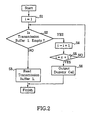
- FIG.2 is a flowchart showing the operation of transmission buffer read controller 13 in the first embodiment.
- FIG.3 is a flowchart showing the operation of receiving buffer read controller 17 in this first embodiment.
- transmission buffer 1 n When reading from transmission buffer 1 n is completed, it insets a dummy cell (S6).
- S6 a dummy cell
- FIG.4 shows the relation between input cells to transmitter TX and output cells from receiver RX according to this first embodiment of the invention.
- input cell There are three kinds of input cell: namely, quality class 1, quality class 2, and idle cells.
- Quality class 1 has been assumed to have a constant cell rate
- quality class 2 has been assumed to have a variable cell rate
- the average cell rate of quality class 1 and quality class 2 has been assumed to be 3 cells/T (seconds).
- Cells are transmitted from transmitter TX to receiver RX at a rate of 6 cells/T (seconds).
- quality class 1 is always transmitted preferentially whatever the fluctuation of cells rate in quality class 2 and any subsequent classes. Therefore, if the length of 1 transmission frame in for example a wireless communication system is T seconds, the cell delay variation of quality class 1 cells is always less than T seconds.
- FIG.5 is a block diagram of this second embodiment.
- this second embodiment has a table, 31, in transmitter TX only.
- a different standard may be set for the aforementioned quality class in each VPI and/or VCI, and transmission cell demultiplexer 11 has table 31 in which are recorded the quality class to these standards.
- Transmission cell demultiplexer 11 distributes cells after referring to this table 31, and attaches an identifier indicating of the quality class to the distributed cells.
- Receiving cell demultiplexer 12 distributes cells in accordance with the identifiers of the received cells. By thus attaching an identifier indicating quality class to a cell table 32 in receiver RX can be omitted.
- FIG.6 is a block diagram of this third embodiment
- FIG.7 is a flowchart showing the operation of receiving buffer read controller 17 according to this third embodiment.
- transmitter TX has time stamp attacher 20 and time stamp counter 22
- receiver RX has time stamp detector 21 and time stamp timing generator 23.
- Time stamp timing generator 23 generates the same timing as time stamp counter 22 of transmitter TX, and can be implemented by means of a time stamp counter which counts synchronously with time stamp counter 22 of transmitter TX.
- time stamp attacher 20 attaches a time stamp showing the arrival time to this cell, in accordance with time stamp counter 22.
- Time stamp counter 22 also transmits a reference time to receiver RX. Cells stored in transmission buffers 1 1 -1 n are transferred to receiver RX and are stored in its receiving buffers 2 1 -2 n , in accordance with the same sort of procedure that was explained in connection with the first embodiment.
- Time stamp detector 21 of receiver RX detects time stamps of cells stored in receiving buffers 2 1 -2 n and generates the cell read timing for receiving buffer read controller 17. This timing is different from the cell output timing that is sent to receiving buffer read controller 17 from output timing generator 18, and constitutes a cell reading schedule generated in accordance with the time stamps detected by time stamp detector 21.
- Time stamp timing generator 23 generates timing on the basis of the reference time received from transmitter TX.
- Output timing generator 18 sends cell output timing to receiving buffer read controller 17 in accordance with this timing generated by time stamp timing generator 23.
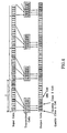
- FIG.8 shows the relation between input cells to transmitter TX and output cells from receiver RX according to this third embodiment.
- the input cell and wireless link conditions are the same as in FIG.4 ; time stamp counter 22 of transmitter TX transmits a reference time to receiver RX at intervals of T; and the time stamp counters of transmitter TX and receiver RX are reset at the reference time interval.
- quality class 2 cells are output with a fixed delay T after the input time, so that errors in cell order do not occur.
- receiver RX can regenerate the arrival intervals of cells that were input to transmitter TX, and in particular the cell transfer delay and cell delay variation of quality class 1 cells can be decreased, and the cell delay variation of quality class 2 cells can also be decreased. Moreover, because receiver RX uses the same time stamp counter as transmitter TX, erroneous cell order caused by the time stamp counters of transmitter TX and receiver RX becoming unsynchronized can be prevented.
- table 32 of receiver RX can be omitted and a table 31 provided in transmitter TX only, if transmission cell demultiplexer 11 distributes cells after referring to this table 31 and attaches an identifier indicative of quality class to the cells; and receiving cell demultiplexer 12 distributes cells in accordance with the identifiers of the received cells.
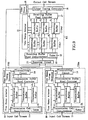
- FIG.9 is a block diagram of this fourth embodiment
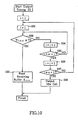
- FIG.10 is a flowchart showing the operation of receiving buffer read controller 17 according to this fourth embodiment.
- transmitters TX1-TXm have time stamp attachers 20 and time stamp timing generators 23, and receiver RX has receiving buffers 2 1(TX1) -2 n(TX1) , 2 1(TX2) -2 n(TX2) , ..., 2 1(TXm) -2 n(TXm) , time stamp detector 21, and time stamp counter 22.
- time stamp timing generator 23 in each transmitter TX1-TXm generates timing on the basis of a reference time received from receiver RX.
- Receiving cell demultiplexer 12 of receiver RX distributes cells received from transmitters TX1-TXm according to quality class and to the transmitter, and stores the cells to receiving buffers 2 1(TX1) -2 n(TX1) , 2 1(TX2) -2 n(TX2) , ..., 2 1(TXm) -2 n(TXm) which correspond to quality classes 1-n and transmitters TX1-TXm.
- Time stamp detector 21 generates a cell read timing corresponding to each receiving buffer 2 1(TX1) -2 n(TX1) , 2 1(TX2) -2 n(TX2) , ..., 2 1(TXm) -2 n(TXm) in accordance with the same procedure as explained in respect of the third embodiment.
- time stamp counter 22 sends a reference time to transmitters TX1-TXm.
- Receiving buffer read controller 17 reads cells from receiving buffers 2 1(TX1) -2 n(TX1) , 2 1(TX2) -2 n(TX2) , ..., 2 1(TXm) -2 n(TXm) according to quality classes 1-n independent of transmitters TX1-TXm. Namely, receiving buffers 2 1(TX1) -2 1(TXm) , all of which correspond to quality class 1, are first of all read in that order, after which reading successively proceeds to receiving buffers corresponding to the next quality class, and finishes with receiving buffers 2 n(TX1) -2 n(TXm) , which correspond to quality class n .
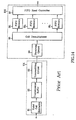
- FIG.11 shows the relation between input cells to transmitters TX1 and TX2 and output cells from receiver RX according to this fourth embodiment.
- transmitters TX1 and TX2 use time stamp timing generators 23 generating the same timing as time stamp counter 22 of receiver RX, receiver RX can multiplex cells from transmitters TX1 and TX2 by having just a single time stamp counter 22. It can also reduce cell delay variation by means of the time stamps.
- table 32 of receiver RX can be omitted and a table 31 provided in transmitters TX1-TXm only, if transmission cell demultiplexers 11 distribute cells after referring to these tables 31 and attach identifiers indicative of quality class to the cells, and receiving cell demultiplexer 12 distributes cells in accordance with the identifiers of the received cells.
- the present invention is capable of meeting the quality requirements for cell delay variation by means of simple, small-scale hardware. It can therefore make efficient use of frequency. It can also make efficient use of allocated bandwidth or time slots.
Claims (6)
- Dispositif pour le transport de cellules ATM comprenant un émetteur (TX) pour émettre des cellules et un récepteur (RX) pour recevoir des cellules, ces cellules étant classées par classe de qualité en fonction des exigences de qualité de transmission ; dans lequel :l'émetteur comprend un démultiplexeur de cellules d'émission (11) apte à distribuer des cellules, en fonction de leur classe de qualité, des tampons d'émission (11-1n), chacun d'eux distinguant et mémorisant des cellules qui ont été distribuées par ce démultiplexeur de cellules d'émission (11) ; et un contrôleur de lecture de tampons d'émission (13) apte à lire des cellules mémorisées dans ces tampons d'émission (11-1n), en commençant par celles qui ont une priorité élevée telle que déterminée par la classe de qualité susmentionnée ; etle récepteur comprend des tampons de réception (21-2n) aptes à mémoriser des cellules reçues, et un contrôleur de lecture de tampons de réception (17) apte à lire des cellules dans ces tampons de réception (21-2n), en commençant par celles qui ont la priorité élevée susmentionnée ;caractérisé en ce que l'émetteur comprend en outre un compteur de marquage temporel (22) et un dispositif pour attacher un marquage temporel (20) qui attache l'instant d'arrivée d'une cellule à cette cellule en tant que marquage temporel en accord avec ce compteur de marquage temporel (22) ;
le récepteur comprend en outre un compteur de marquage temporel qui produit les mêmes valeurs temporelles que le compteur de marquage temporel (22) de l'émetteur, et un détecteur de marquage temporel (21) pour détecter les marquages temporels de cellules mémorisées dans les tampons de réception ; et le contrôleur de lecture de tampons de réception comprend des moyens pour lire des cellules mémorisées dans les tampons de réception (21-2n) en fonction de ces marquages temporels, sur la base du compteur de marquage temporel du récepteur. - Dispositif pour le transport de cellules ATM comprenant un émetteur (TX) pour émettre des cellules et un récepteur (RX) pour recevoir des cellules, ces cellules étant classées par classe de qualité en fonction d'exigences de qualité de transmission ; dans lequel :l'émetteur comprend un démultiplexeur de cellules d'émission (11) apte à distribuer des cellules, en fonction de leur classe de qualité, des tampons d'émission (11-1n), chacun d'eux distinguant et mémorisant des cellules qui ont été distribuées par le démultiplexeur de cellules d'émission (11) ; et un contrôleur de lecture de tampons d'émission (13) apte à lire des cellules mémorisées dans ces tampons d'émission (11-1n), en commençant par celles qui ont une priorité élevée telle que déterminée par la classe de qualité susmentionnée ; etle récepteur comprend des tampons de réception (21-2n) aptes à mémoriser des cellules reçues, et un contrôleur de lecture de tampons de réception (17) apte à lire des cellules dans ces tampons de réception (21-2n), en commençant par celles qui ont la priorité élevée susmentionnée ;caractérisé en ce que le récepteur comprend en outre un compteur de marquage temporel et un détecteur de marquage temporel (21) pour détecter les marquages temporels de cellules mémorisées dans les tampons de réception (21-2n), et le contrôleur de lecture de tampons de réception (17) comprend des moyens pour lire des cellules mémorisées dans les tampons de réception en fonction de ces marquages temporels, sur la base de ce compteur de marquage temporel ; et
l'émetteur comprend en outre un compteur de marquage temporel (22) qui produit les mêmes valeurs temporelles que le compteur de marquage temporel du récepteur, et un dispositif pour attacher un marquage temporel (20) qui attache l'instant d'arrivée d'une cellule à cette cellule en tant que marquage temporel en accord avec ce compteur de marquage temporel (22) de l'émetteur. - Dispositif pour transporter des cellules ATM selon la revendication 1 ou 2, dans lequel le récepteur comporte un démultiplexeur de cellules de réception pour distribuer des cellules reçues en fonction de leur classe de qualité, et chacun des tampons de réception distingue et mémorise des cellules qui ont été distribuées par ce démultiplexeur de cellules de réception.
- Dispositif pour transporter des cellules ATM selon la revendication 3, dans lequel les classes de qualité peuvent être mises à différentes valeurs sur chaque VPI et/ou VCI, et le démultiplexeur de cellules d'émission et/ou le démultiplexeur de cellules de réception comprennent une table dans laquelle sont enregistrées les classes de qualité en fonction de ces valeurs, et des moyens pour distribuer des cellules après avoir fait référence à cette table.
- Dispositif pour transporter des cellules ATM selon la revendication 3, dans lequel les classes de qualité peuvent être mises à différentes valeurs sur chaque VPI et/ou VCI ; le démultiplexeur de cellules d'émission comprend une table dans laquelle sont enregistrées les classes de qualité en fonction de ces valeurs, des moyens pour distribuer des cellules après avoir fait référence à cette table, et des moyens pour attacher un identificateur indiquant la classe de qualité à une cellule distribuée ; et le démultiplexeur de cellules de réception comprend des moyens pour distribuer des cellules en fonction des identificateurs des cellules reçues.
- Dispositif pour transporter des cellules ATM selon la revendication 2, dans lequel il y a une pluralité d'émetteurs ; et
le démultiplexeur de cellules de réception comprend des moyens pour distribuer des cellules en fonction de la classe de qualité et de l'émetteur à partir duquel elles sont arrivées ; chaque tampon de réception comprend des moyens pour distinguer et mémoriser ces cellules distribuées ; et le contrôleur de lecture de tampons de réception comprend des moyens pour lire préférentiellement des cellules, en commençant par celles qui ont une priorité élevée telle que déterminée par la classe de qualité, indépendamment de l'émetteur à partir duquel une cellule est arrivée.
Applications Claiming Priority (2)
| Application Number | Priority Date | Filing Date | Title |
|---|---|---|---|
| JP135388/96 | 1996-05-29 | ||
| JP13538896 | 1996-05-29 |
Publications (3)
| Publication Number | Publication Date |
|---|---|
| EP0810808A2 EP0810808A2 (fr) | 1997-12-03 |
| EP0810808A3 EP0810808A3 (fr) | 1998-08-19 |
| EP0810808B1 true EP0810808B1 (fr) | 2009-08-12 |
Family
ID=15150547
Family Applications (1)
| Application Number | Title | Priority Date | Filing Date |
|---|---|---|---|
| EP97303609A Expired - Lifetime EP0810808B1 (fr) | 1996-05-29 | 1997-05-28 | Dispositif pour le transport de cellules ATM |
Country Status (3)
| Country | Link |
|---|---|
| US (1) | US6188697B1 (fr) |
| EP (1) | EP0810808B1 (fr) |
| DE (1) | DE69739531D1 (fr) |
Families Citing this family (17)
| Publication number | Priority date | Publication date | Assignee | Title |
|---|---|---|---|---|
| SE509186C2 (sv) * | 1996-06-25 | 1998-12-14 | Ericsson Telefon Ab L M | Anordning och metod vid behandling av redundanssignaler och ett telekommunikationssystem omfattande densamma |
| FI104671B (fi) * | 1997-07-14 | 2000-04-14 | Nokia Networks Oy | Kytkentäkenttäjärjestely |
| US6937566B1 (en) * | 1997-07-25 | 2005-08-30 | Telefonaktiebolaget Lm Ericsson (Publ) | Dynamic quality of service reservation in a mobile communications network |
| JPH11131633A (ja) * | 1997-11-01 | 1999-05-18 | Kamano Kensetsu Kk | 木炭ブロック |
| JP3589851B2 (ja) * | 1998-02-20 | 2004-11-17 | 株式会社日立製作所 | パケット通信システム及びパケット通信装置 |
| JP3077677B2 (ja) * | 1998-07-14 | 2000-08-14 | 日本電気株式会社 | 品質保証ノード装置 |
| GB9929794D0 (en) * | 1999-12-16 | 2000-02-09 | Nokia Networks Oy | Data transmission apparatus |
| JP2001292148A (ja) * | 2000-02-01 | 2001-10-19 | Hitachi Ltd | Atm通信装置及びその帯域制御方法 |
| FR2806244B1 (fr) * | 2000-03-13 | 2003-05-30 | Mitsubishi Electric Inf Tech | Procede de transmission entre une station de base d'un reseau d'acces et un controleur de reseau d'acces d'un systeme de telecommunications |
| FI20000853A (fi) * | 2000-04-10 | 2001-10-11 | Nokia Networks Oy | Tiedonsiirtomenetelmä |
| US6404737B1 (en) * | 2000-08-10 | 2002-06-11 | Ahead Communications Systems, Inc. | Multi-tiered shaping allowing both shaped and unshaped virtual circuits to be provisioned in a single virtual path |
| US7039056B2 (en) * | 2001-08-02 | 2006-05-02 | Lucent Technologies Inc. | High quality audio and video over digital subscriber lines (DSLs) |
| WO2003045017A1 (fr) * | 2001-11-20 | 2003-05-30 | Siemens Aktiengesellschaft | Procede pour la transmission de donnees en paquets dans un systeme de communication radio |
| EP1584164A2 (fr) * | 2002-12-31 | 2005-10-12 | Conexant, Inc. | Systeme et procede pour assurer une qualite de service dans la transmission de cellules en mode de transfert asynchrone |
| WO2007126892A2 (fr) * | 2006-04-04 | 2007-11-08 | Orion Enterprises, Inc. | Joint et méthode de jonction pour tube composite à multiples couches |
| CA2700404A1 (fr) | 2007-09-24 | 2009-04-02 | Ceragon Networks Ltd. | Communications a debit de donnees variables sans resultat et sans erreur |
| US8270291B2 (en) | 2007-09-24 | 2012-09-18 | Ceragon Networks Ltd. | Protected variable data rate communication systems |
Family Cites Families (16)
| Publication number | Priority date | Publication date | Assignee | Title |
|---|---|---|---|---|
| US5130885A (en) * | 1991-07-10 | 1992-07-14 | Micron Technology, Inc. | Dram cell in which a silicon-germanium alloy layer having a rough surface morphology is utilized for a capacitive surface |
| US5313454A (en) * | 1992-04-01 | 1994-05-17 | Stratacom, Inc. | Congestion control for cell networks |
| DE4328862A1 (de) * | 1993-08-27 | 1995-03-02 | Sel Alcatel Ag | Verfahren und Vorrichtung zum Zwischenspeichern von Datenpaketen sowie Vermittlungsstelle mit einer solchen Vorrichtung |
| DE69416849T2 (de) * | 1993-10-26 | 1999-07-08 | Northern Telecom Ltd | Digitale übertragungsstrecke zum effizienten transport von gemischten paketklassen |
| JP3354689B2 (ja) * | 1994-02-28 | 2002-12-09 | 富士通株式会社 | Atm交換機、交換機及びそのスイッチングパス設定方法 |
| JPH07254906A (ja) * | 1994-03-16 | 1995-10-03 | Mitsubishi Electric Corp | 優先処理機能を有するシフトレジスタ、それを用いたパケット通信用スイッチング装置及びそれを用いたatmネットワーク並びに優先処理を伴うパケット通信方式及び優先処理を伴うatm通信方式 |
| JP2655481B2 (ja) * | 1994-04-28 | 1997-09-17 | 日本電気株式会社 | 出力バッファ型atmスイッチにおける優先制御方法 |
| FI98774C (fi) * | 1994-05-24 | 1997-08-11 | Nokia Telecommunications Oy | Menetelmä ja laitteisto liikenteen priorisoimiseksi ATM-verkossa |
| US5487061A (en) * | 1994-06-27 | 1996-01-23 | Loral Fairchild Corporation | System and method for providing multiple loss and service priorities |
| JPH08163145A (ja) * | 1994-12-08 | 1996-06-21 | Nec Corp | Atm交換機のトラフィックシェーピング方法とその装置 |
| US5768273A (en) * | 1995-04-05 | 1998-06-16 | International Business Machines Corporation | Method and apparatus for priority level queueing in processing ATM cell header and payload |
| US5822317A (en) * | 1995-09-04 | 1998-10-13 | Hitachi, Ltd. | Packet multiplexing transmission apparatus |
| JP3545110B2 (ja) * | 1995-09-26 | 2004-07-21 | 富士通株式会社 | 通信サービスの品質制御方式 |
| US5684791A (en) * | 1995-11-07 | 1997-11-04 | Nec Usa, Inc. | Data link control protocols for wireless ATM access channels |
| US5793747A (en) * | 1996-03-14 | 1998-08-11 | Motorola, Inc. | Event-driven cell scheduler and method for supporting multiple service categories in a communication network |
| US5828653A (en) * | 1996-04-26 | 1998-10-27 | Cascade Communications Corp. | Quality of service priority subclasses |
-
1997
- 1997-05-28 EP EP97303609A patent/EP0810808B1/fr not_active Expired - Lifetime
- 1997-05-28 DE DE69739531T patent/DE69739531D1/de not_active Expired - Lifetime
- 1997-05-29 US US08/864,783 patent/US6188697B1/en not_active Expired - Fee Related
Also Published As
| Publication number | Publication date |
|---|---|
| EP0810808A3 (fr) | 1998-08-19 |
| US6188697B1 (en) | 2001-02-13 |
| EP0810808A2 (fr) | 1997-12-03 |
| DE69739531D1 (de) | 2009-09-24 |
Similar Documents
| Publication | Publication Date | Title |
|---|---|---|
| US7103063B2 (en) | Apparatus and method for facilitating data packet transportation | |
| EP0810808B1 (fr) | Dispositif pour le transport de cellules ATM | |
| US5999534A (en) | Method and apparatus for scheduling cells for use in a static priority scheduler | |
| EP0337619B1 (fr) | Système de communication | |
| US6556576B1 (en) | Local area network with a bridge terminal for transmitting data between a plurality of sub-networks | |
| US5007048A (en) | Circuit arrangement for avoiding overload in a wideband switching system | |
| EP0119105B1 (fr) | Système intégré de commutation circuit/pacquet | |
| EP0961522B1 (fr) | Nouveau procédé et dispositif de mise en forme du trafic dans un système d'access à large bande, basée sûr fibre optique | |
| EP0817428B1 (fr) | Circuit de mise en forme de trafic aux voies virtuelles avec plusieurs files d'attente | |
| CA2224753C (fr) | Systeme de mise en file d'attente pour commutateur mta | |
| CA2043600C (fr) | Transmissions a debit binaire constant dans un commutateur de donnees a large bande | |
| US10841674B2 (en) | Timeslot management method, a related network terminator, a related line terminator and an upstream signal frame structure for a time division multiple access system | |
| US6560219B1 (en) | Hybrid exchange, an exchange, and a re-arrangement method for STM data in an exchange | |
| KR100452952B1 (ko) | 비동기 전송방식 네트워크에서 데이터 셀 전송 스케줄링 방법 | |
| KR100341794B1 (ko) | 패킷전송방법, 패킷전송장치, 무선프레임 전송방법, 이동통신방법, 이동통신시스템 및 교환국 | |
| US6658009B1 (en) | Band allocation method and transmission system for transmitting variable-length packets | |
| EP1065908B1 (fr) | Méthode pour générer des cellules ATM pour des applications à faible débit | |
| EP1164812B1 (fr) | Système et procédé d'attribution dynamique de bande passante capable de réduire le délai de transmission de cellules | |
| JP3537991B2 (ja) | Atmセル伝送装置 | |
| US7130267B1 (en) | System and method for allocating bandwidth in a network node | |
| KR100334318B1 (ko) | 에이에이엘2 에이티엠 전송 장치 및 방법 | |
| JPH09321772A (ja) | Atmセル無線伝送装置 | |
| JP2002247064A (ja) | 親局装置、子局装置及び通信システム | |
| Angelopoulos | Time division sharing of tree passive optical networks (PONs) by ATM users: a method to control cell jitter | |
| GB2335328A (en) | Permanent virtual circuit communication system |
Legal Events
| Date | Code | Title | Description |
|---|---|---|---|
| PUAI | Public reference made under article 153(3) epc to a published international application that has entered the european phase |
Free format text: ORIGINAL CODE: 0009012 |
|
| AK | Designated contracting states |
Kind code of ref document: A2 Designated state(s): DE FR GB |
|
| PUAL | Search report despatched |
Free format text: ORIGINAL CODE: 0009013 |
|
| AK | Designated contracting states |
Kind code of ref document: A3 Designated state(s): DE FR GB |
|
| 17P | Request for examination filed |
Effective date: 19990216 |
|
| AKX | Designation fees paid |
Free format text: DE FR GB |
|
| RBV | Designated contracting states (corrected) |
Designated state(s): DE FR GB |
|
| 17Q | First examination report despatched |
Effective date: 20061030 |
|
| GRAP | Despatch of communication of intention to grant a patent |
Free format text: ORIGINAL CODE: EPIDOSNIGR1 |
|
| GRAC | Information related to communication of intention to grant a patent modified |
Free format text: ORIGINAL CODE: EPIDOSCIGR1 |
|
| GRAS | Grant fee paid |
Free format text: ORIGINAL CODE: EPIDOSNIGR3 |
|
| GRAA | (expected) grant |
Free format text: ORIGINAL CODE: 0009210 |
|
| AK | Designated contracting states |
Kind code of ref document: B1 Designated state(s): DE FR GB |
|
| REG | Reference to a national code |
Ref country code: GB Ref legal event code: FG4D |
|
| REF | Corresponds to: |
Ref document number: 69739531 Country of ref document: DE Date of ref document: 20090924 Kind code of ref document: P |
|
| PLBE | No opposition filed within time limit |
Free format text: ORIGINAL CODE: 0009261 |
|
| STAA | Information on the status of an ep patent application or granted ep patent |
Free format text: STATUS: NO OPPOSITION FILED WITHIN TIME LIMIT |
|
| PGFP | Annual fee paid to national office [announced via postgrant information from national office to epo] |
Ref country code: GB Payment date: 20100329 Year of fee payment: 14 |
|
| 26N | No opposition filed |
Effective date: 20100517 |
|
| PGFP | Annual fee paid to national office [announced via postgrant information from national office to epo] |
Ref country code: FR Payment date: 20100525 Year of fee payment: 14 |
|
| PGFP | Annual fee paid to national office [announced via postgrant information from national office to epo] |
Ref country code: DE Payment date: 20100526 Year of fee payment: 14 |
|
| REG | Reference to a national code |
Ref country code: DE Ref legal event code: R119 Ref document number: 69739531 Country of ref document: DE |
|
| REG | Reference to a national code |
Ref country code: DE Ref legal event code: R119 Ref document number: 69739531 Country of ref document: DE |
|
| GBPC | Gb: european patent ceased through non-payment of renewal fee |
Effective date: 20110528 |
|
| REG | Reference to a national code |
Ref country code: FR Ref legal event code: ST Effective date: 20120131 |
|
| PG25 | Lapsed in a contracting state [announced via postgrant information from national office to epo] |
Ref country code: FR Free format text: LAPSE BECAUSE OF NON-PAYMENT OF DUE FEES Effective date: 20110531 |
|
| PG25 | Lapsed in a contracting state [announced via postgrant information from national office to epo] |
Ref country code: GB Free format text: LAPSE BECAUSE OF NON-PAYMENT OF DUE FEES Effective date: 20110528 |
|
| PG25 | Lapsed in a contracting state [announced via postgrant information from national office to epo] |
Ref country code: DE Free format text: LAPSE BECAUSE OF NON-PAYMENT OF DUE FEES Effective date: 20111130 |